
Subscribe to Our Youtube Channel
Related Manuals for Image Engineering camSPECS


Summary of Contents for Image Engineering camSPECS
- Page 1 User Manual 29. April 2020 Image Engineering GmbH & Co. KG · Im Gleisdreieck 5 . 50169 Kerpen-Horrem . Germany T +49 2234 2273 99 99 1-0 . F +49 2234 2273 99 99 1-10 . www.image-engineering.com...
-
Page 2: Table Of Contents
3.4 Camera settings ....................7 3.4.1 Camera position and lenses used ..............7 3.4.2 Exposure ......................7 OPERATING INSTRUCTIONS SOFTWARE ..............8 4.1 To install camSPECS software................8 4.2 RAW file conversion ....................8 4.3 Workflow ....................... 8 4.3.1 Spectral sensitivity (camSPECS) module ............8 4.3.2 Spectral sensitivity (iQ-LED) module..............9... - Page 3 4.9 ICC profile evaluation ...................29 4.10 Calibration......................30 4.11 Use of the in-situ database ...................33 4.12 Known issues .......................34 4.13 Trademark and Copyright ..................34 ADDITIONAL INFORMATION ..................35 5.1 Maintenance ......................35 5.2 Disposal instructions .....................35 TECHNICAL DATASHEET ..................36 Image Engineering Seite 3 von 36...
-
Page 4: Introduction
The included calibration spectrometer is used for periodic on-site calibration. The camSPECS software measures spectral sensitivity by capturing images of the filter plate taken with a camera system. -
Page 5: Getting Started
Calibration device Commissioning • Remove the packaging material. • The plug for the power supply and the main switch is on the box's backside. Connect camSPECS with a power socket and switch it on. Image Engineering Page 5 of 36... -
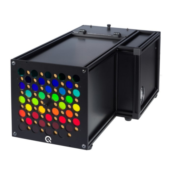
Page 6: Operating Instructions Hardware
OPERATING INSTRUCTIONS HARDWARE camSPECS Switch camSPECS on and let it run for a couple of minutes (>= 4 min) until it reaches a stable temperature. Filter panel A set of 39 interference filters is used to generate narrow-band light. The filters cover a range of 380 - 760 nm in 10 nm steps. -
Page 7: Camera Settings
Ensure that the filters are the only light sources captured by the camera. The pictures should be taken in a dark room, or the space between the camera and the camSPECS box should be shielded to avoid stray light or other light hitting the camera sensor. -
Page 8: Operating Instructions Software
RAW file conversion camSPECS uses dcraw to convert typical camera raw images to TIFF images. There is a list of all supported cameras at: www.cybercom.net/~dcoffin/dcraw/ Standard processing converts to linear TIFF files while retaining the CFA pattern. A dark frame subtraction (DFS) is supported to suppress fixed pattern noise. -
Page 9: Spectral Sensitivity (Iq-Led) Module
• The spectral curves can be saved as an image file for documentation purposes. 4.3.2 Spectral sensitivity (iQ-LED) module • Start the camSPECS software and switch to module Spectral sensitivity (iQ-LED). • Select the Spectral Sensitivity Database. • Select the module Dark frame subtraction and the image file for an optional dark image. -
Page 10: Icc Profile Evaluation Module
Explanation of the sample data: • Spectral Sensitivity (camSPECS) module, camSPECS XL folder: XL_Calibration.txt – sample input calibration file for the camSPECS image. Not applicable for customer’s hardware. camspecs.ARW– sample input raw capture of camSPECS filter plate. -
Page 11: Image Data
See www.cybercom.net/~dcoffin/dcraw/ for a list of all supported cameras. On this site, there is a link to the latest executable version of dcraw. To update dcraw, replace the dcraw.exe with the new one in the “app” directory of the camSPECS program. Or choose dcraw from a different location in the advanced settings. -
Page 12: Color Filter Array (Bayer Pattern)
Sometimes it might be necessary to set the CFA manually. To determine how the pixels are located in the CFA, see the corresponding filters in an image taken with camSPECS. These filters represent blue, green, and red. Non-standard color filter arrays are supported: select 'C' (for Clear) for each channel in the corresponding drop-down menu in the advanced settings panel. -
Page 13: Spectral Sensitivity (Camspecs) Module
Description of the numbered controls marked in the image above: 1. Select the calibration file for the camSPECS hardware. Calibration files can be added and removed from the list using the '+' and '-' buttons. The' S' button can save all calibration files to a specified location. - Page 14 – these should be converted to 16-bit Tiff images first.). Depending on the selected calibration file (see item 1), one or more images can be chosen that contain the filter arrangement of camSPECS. The '+,' '-,' and 'C' buttons are options to add images, remove one selected image or clear the whole list. After the measurement, the spectral curve of the first image in the list is displayed.
- Page 15 10. Export the spectral curves to an image (JPEG, PNG, TIFF, BMP, GIF) for documentation purposes. Figure 4.5.1: A tiled image is created from all images of a series for camSPECS multi-shot. Displaced filter frames can easily be identified. Figure 4.5.2: camSPECS filter capture with adjustable ROIs for modifying measurement areas.
-
Page 16: Advanced Settings
7. Select the dcraw application (see note below). By default, the dcraw version delivered with the software is used and located in the directory "app" inside the camSPECS program directory. For raw image processing, camSPECS uses dcraw to convert standard camera raw files to TIFF files, and the converted images are saved to a sub-directory named 'converted.'... - Page 17 ROI locations. The preceding filter detection is automatic, and the ROIs can be activated and aligned with the mouse. Semi-automatic detection of the filters in camSPECS. The ROIs shown in this example were set to a size of 50% (left), respectively 70% (right) of the diameter of the corresponding filters.
-
Page 18: Spectral Sensitivity (Iq-Led)
The database is created with a monochromator such as camSPECS then data from a test camera is selected for parameter optimization and comparison of results as described below. This process can be repeated for additional test cameras to confirm that the optimized parameters are robust across the cameras under test. - Page 19 1. Select 43 camera modules that are representative of the expected production variation. 2. Select one of the camera modules to optimize the exposure of the camSPECS filter plate, allowing for adequate headroom. Capture a black frame with these settings.
- Page 20 7. Launch the camSPECS software Spectral sensitivity (iQ-LED) module and load the dark frame, image folder, and spectra folder as described below. With the default settings, click Start, and after completion, open the cameraRGBs.txt file output in the images folder, illustrated in columns C:E below.
- Page 21 2. This module captures the iQ-LED device using the adjusted stored illuminants, as seen above. 3. Launch the camSPECS software Spectral sensitivity (iQ-LED) module. Load the custom spectral sensitivity database, the dark frame for this camera module, the image and spectra folders corresponding to the adjusted stored illuminants, and with the default settings, click Start.
- Page 22 It is assumed that a minimum representative sampling of 30 cameras has been measured previously with camSPECS as described in section 4.5 item 8 or another monochromator and that these reference spectral sensitivities have been saved in the correct SS_RGB.txt format.
- Page 23 The naming convention for the exported and any additional white spectra is illustrated in the iQ-LED Images window. If White is checked, the corresponding Image/Spectrum pair will be used to white-balance the computed spectral sensitivities. Illuminant E is recommended for this Image Engineering Page 23 of 36...
- Page 24 • Reference Spectral Sensitivities allows entry of the known spectral sensitivities file for the test camera measured with camSPECS. If entered, the Difference shows the mean squared error between the computed and the Reference Spectral Sensitivities. The parameters described above can be quantitatively optimized by monitoring the difference for the set of test cameras.
-
Page 25: Validation Module
Columns must be separated with a tabulator. The files in the /calibration_files/light source directory of the camSPECS program folder may be used as a template. Format the file corresponding to these files, copy it to this folder and then restart camSPECS. -
Page 26: Color Transforms Module
In the displayed result, each patch's measured digital values (red, green, and blue) are plotted against the predicted digital values. All values are normalized to a range between 0 and 1. If the exposure and measurement setup is highly accurate, all RGB data points in this plot should be close to the white diagonal line (best correlation). - Page 27 1. Select a Camera Spectral Sensitivities file (.txt) with values interpolated to 5 nm (see advanced settings) created by camSPECS. 2. Select the desired transform type from those available. • Matrix – Colorimetric creates a 3x3 matrix from camera RGB to XYZ for the specified Reference illuminant.
- Page 28 (/calibration_files/reflectance). Make sure to restart camSPECS to use the new files in this menu. An optimal camera can be built by obtaining the in-situ data and installing it in the C:/Program Files/Image Engineering/ camSPECS folder.
-
Page 29: Icc Profile Evaluation
Toggling amongst the profile, None, or Use Profile TRC allows separate visualization of the effect of both components. 5. Export image saves the white-balanced, 16-bit, linear RGB image with the ICC profile embedded. Image Engineering Page 29 of 36... -
Page 30: Calibration
4.10 Calibration A calibration device is delivered with the camSPECS hardware. A positioning plate for the aperture of the fiber is also included in the delivery. Easily place the plate in front of the filters and mount it, so the missing hole is at the bottom right (see the image below). - Page 31 A failed measurement may be repeated, e.g., if a wrong filter was measured. The next filter in the queue is highlighted in the display of the camSPECS filter matrix. After the measurement procedure is finished, a new calibration file is created and is immediately available in the spectral response module.
- Page 32 8. The following filter to be measured is displayed in the image. Mount the calibration plate in front of the filters and tighten it with the screw cap. Push the measuring head into the holes of the calibration plate as far as it will go. Image Engineering Page 32 of 36...
-
Page 33: Use Of The In-Situ Database
.csv file that then needs to be copied to the directory C:/Program Files/Image Engineering/ camSPECS V…/calibration_files/reflectance” to make it available for CCM calculation. After a restart of camSPECS, the new radiance data is available in menu “Training data” in the Image Engineering... -
Page 34: Known Issues
Windows is a registered trademark of Microsoft Corp. and Matlab is a registered trademark of Mathworks Corp. Software by Third Parties dcraw -- Dave Coffin's raw photo decoder Copyright 2016 by Dave Coffin dcoffin@cybercom.net (www.cybercom.net/~dcoffin/dcraw/) Copyright Information See separate Terms and Conditions document. Image Engineering Page 34 of 36... -
Page 35: Additional Information
Do not remove the fiber from the calibration device; otherwise, the calibration is invalid. Disposal instructions After the service life of camSPECS and the spectroradiometer, they must be disposed of properly. Electrical and electromechanical components are included in camSPECS and the spectroradiometer. -
Page 36: Technical Datasheet
6 TECHNICAL DATASHEET See annex for the technical data sheet. It can also be downloaded from the website of Image Engineering: https://image-engineering.de/support/downloads. Image Engineering Page 36 of 36...
Need help?
Do you have a question about the camSPECS and is the answer not in the manual?
Questions and answers