Table of Contents
Advertisement
Quick Links
UM2725
User manual
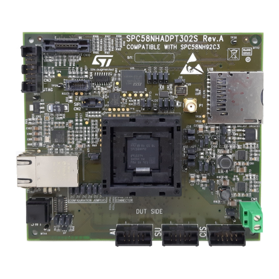
SPC58NHADPT302S Rev.A evaluation board
Introduction
The SPC58NHADPT302S Rev.A evaluation board supports STMicroelectronics SPC58NH92 microcontroller in FPBGA
17X17X1.8 302.
Figure 1.
SPC58NHADPT302S Rev.A
Note: picture is not contractual.
UM2725 - Rev 1 - June 2020
www.st.com
For further information contact your local STMicroelectronics sales office.
Advertisement
Table of Contents

Subscribe to Our Youtube Channel
Related Manuals for STMicroelectronics SPC58NHADPT302S


Summary of Contents for STMicroelectronics SPC58NHADPT302S
-
Page 1: Figure 1. Spc58Nhadpt302S Rev.a
UM2725 User manual SPC58NHADPT302S Rev.A evaluation board Introduction The SPC58NHADPT302S Rev.A evaluation board supports STMicroelectronics SPC58NH92 microcontroller in FPBGA 17X17X1.8 302. Figure 1. SPC58NHADPT302S Rev.A Note: picture is not contractual. UM2725 - Rev 1 - June 2020 www.st.com For further information contact your local STMicroelectronics sales office. -
Page 2: Overview
An SPC58NHADPT302S Rev. A adapter package includes the following items: • SPC58NHADPT302S Rev. A mini module • Mini CD with user manual and schematics Supported devices The SPC58NHADPT302S Rev. A mini module supports the SPC58NH family of microcontrollers in FPBGA 17X17X1.8 302. UM2725 - Rev 1 page 2/38... -
Page 3: License Agreement
Upon breaking the seal, you and STMicroelectronics entered into the evaluation board license agreement, a copy of which is also enclosed with the evaluation board for convenience. -
Page 4: Handling Precautions
UM2725 Handling precautions Handling precautions Please take care to handle the package contents in a manner such as to prevent electrostatic discharge. Before the EVB is used or power is applied, please fully read the following sections on how to correctly configure the board. -
Page 5: Features
UM2725 Hardware description Hardware description Hardware features The SPC58NHADPT302S Rev. A mini module board has the following features: • Connector for external power supplies input (5 V) used in stand-alone mode • Reset button with driver and led indicator •... -
Page 6: Hardware Dimension
PCB area: 127 mm x 114.3 mm • Top components height: 20 mm max • Bottom components height: 3.5 mm max • PCB thickness: 1.6 mm Figure 2. SPC58NHADPT302S Rev. A top component view UM2725 - Rev 1 page 6/38... -
Page 7: Power And System Configuration
In this setup, the external power supply input available on the mini module should NOT be used. When the SPC58NHADPT302S Rev. A mini module is used as a stand-alone board, 5V0 voltages must be supplied externally, 3V3 and 1V2 voltages will be generated internally by specific circuit on the mini module. -
Page 8: Jtag/Lfast Lvds/ Sipi Interface Configuration
The following jumpers need to configure the JTAG/LFAST LVDS/SIPI: Table 2. JTAG/LFAST/SIPI configuration jumpers Jumper Description Default Position SIPI pin 3 configuration Figure 8. Overview of SPC58NHADPT302S Rev. A • 1-2: RDY mini module - Top - B3 (RDY) • 2-3: PA14 TDI_LF configuration Figure 8. -
Page 9: System Clock Configuration
The mini module supports the usage of crystal clock sources as well as external clock source: Table 3. Clock configuration jumpers Jumper Description Default Position XTAL32 configuration Figure 8. Overview of SPC58NHADPT302S Rev. A Open • Close: connect pin 2 of 32.768 KHz mini module - Top - C3 crystal (Y2) to XTAL32 EXTAL32 configuration Figure 8. -
Page 10: Other Jumpers
Other jumpers Jumper Description Default Position Close Figure 8. Overview of SPC58NHADPT302S Rev. A Testmode settings (10 KΩ down) mini module - Top - B2 Configuration for pin shared between eMMC & SD Card Reader The following jumpers need to configure the pin shared between eMMC & SD Card Reader set the jumpers described in the table below. -
Page 11: Hardware Description
1 Gb/s Ethernet interface Jumper Description Position ESD Protection Figure 8. Overview of SPC58NHADPT302S Rev. A mini module - Top - A3 ESD Protection Figure 8. Overview of SPC58NHADPT302S Rev. A mini module - Top - A3 Ethernet 1-Port GigabitEthrnt Figure 8. -
Page 12: Hyperbus Interface
Hyperbus interface This paragraph describes the Hyperbus interface present on the mini module. The SPC58NHADPT302S contains only one CS (CNS), whereas the memory device contains two CSs lines, one for RAM and one for FLASH. The second CS is emulated using one GPIO signal (PA[15]). -
Page 13: Emmc Interface
The figure below shows the functional diagram of the eMMC interface. Figure 6. eMMC functional diagram Table 10. eMMC interface Symbol Description Position eMMC memory 8 GB Figure 8. Overview of SPC58NHADPT302S Rev. A mini module - Top - B1 UM2725 - Rev 1 page 13/38... -
Page 14: Sd/Mmc Interface
SD/MMC interface Symbol Description Position CMOS switch Figure 9. Overview of SPC58NHADPT302S Rev. A mini module - Bottom - A2 Filter EMI 6-line Micro Figure 9. Overview of SPC58NHADPT302S Rev. A mini module - Bottom - B2 Connector SD reverse push-push Figure 8. -
Page 15: Cis, Isu And Ai Connectors
5 mm between each other. The connectors have the following features: Connector 1 (CAN/IO/SPI): CN7 (Figure 8. Overview of SPC58NHADPT302S Rev. A mini module - Top - B4). Serigraphy: CIS •... -
Page 16: Table 13. Isu - Cn8 Connector Pin Mapping
GPIO_126/PCS_1[0] PH[14] GPIO_83/PCS_1[1] PF[3] GPIO_82/PCS_1[2] PF[2] VSS_HV VSS_HV Connector 3 (ADC/IO): CN9 (Figure 8. Overview of SPC58NHADPT302S Rev. A mini module - Top - D4) Serigraphy: AI • Power supplies, VSS, VDD_HV_5v0 • 1xADC (8 signal) • 8xGPIO Table 14. -
Page 17: Other Connectors
Table 16. Test points Test point Description Position VDD_HV_IO_MAIN Figure 8. Overview of SPC58NHADPT302S Rev. A mini module - Top - D2 VSS_OSC Figure 8. Overview of SPC58NHADPT302S Rev. A mini module - Top - C2 AGND Figure 8. Overview of SPC58NHADPT302S Rev. A mini module - Top... - Page 18 UM2725 Test points Test point Description Position TP22 D7_HB Figure 8. Overview of SPC58NHADPT302S Rev. A mini module - Top - B2 TP23 RWDS_HB Figure 8. Overview of SPC58NHADPT302S Rev. A mini module - Top - B2 TP24 CMD_eMM Figure 8. Overview of SPC58NHADPT302S Rev. A mini module - Top...
-
Page 19: Layout Overview
UM2725 Layout overview Layout overview Figure 8. Overview of SPC58NHADPT302S Rev. A mini module - Top UM2725 - Rev 1 page 19/38... -
Page 20: Figure 9. Overview Of Spc58Nhadpt302S Rev. A Mini Module - Bottom
UM2725 Layout overview Figure 9. Overview of SPC58NHADPT302S Rev. A mini module - Bottom UM2725 - Rev 1 page 20/38... -
Page 21: Bom
UM2725 Table 17. Ref. designator Value Description Manufacturer Manufcode C11, C16, C19, C22, C25, C42, C47, C50, C53, C56, C79, C85, C86, C87, C89, C90, C92, C95, C96, C97, C99, C103, C104, 100 nF Mult. cer. cap. Murata GCM188R71H104KA57D C105, C106, C107, C108, C110, C111, C112, C113,... - Page 22 UM2725 Ref. designator Value Description Manufacturer Manufcode C6, C12, C17, C20, C23, C26, C29, C32, C35, C38, C41, C43, C45, C48, C51, C54, C57, C93, C100, C125, C128, C131, C134, C137, C140,C143, C6, 10 nF Mult. cer. cap. Murata GCM188R71H103KA37D C12, C17, C20, C23, C26, C29, C32, C35, C38,...
- Page 23 UM2725 Ref. designator Value Description Manufacturer Manufcode Laird-Signal Integrity FBEAD1 100R Multilayer ferrite HI1206N101R-10 Products Strip male 2 pin, 1 FCCU1, J18, J20, row, 180° STRIP2PMD-2MM-O Harwin M22-2512005 (see mech part) CD74AC32M TTL OR gate Texas Instruments CD74AC32M J1, J2, J3, J4, J5, J6, J8, J9, J10, J11, J12, J13, Strip male 3 pin, 1...
- Page 24 TP23, TP24, TP25, TP26 TP11 TP-STRIP Test point - ignore Socket Yamaichi FPBGA302 NP351-302-772 Yamaichi NP351-302-774 (N5) U2, U3 A6986 Volt. reg STMicroelectronics A6986 8MHz Clock oscillator ECS-3953M-080-BN-TR 74LVC125AMTR HCMOS buffer STMicroelectronics 74LVC125AMTR 74V1G08STR CMOS AND gate STMicroelectronics 74V1G08STR U9,U10...
- Page 25 NC7WZU04P6X CMOS inverter ON Semiconductor NC7WZU04P6X eMMC memory 8 IS21ES08G-JCLI GB 3.3 V 200 Mhz ISSI IS21ES08G-JCLI eMMC NAND flash STMPS2151MTR CMOS switch STMicroelectronics STMPS2151MTR Filter EMI 6-line EMIF06-MSD02N16 STMicroelectronics EMIF06-MSD02N16 micro Connector SD 1775059-1 TE Connectivity 1775059-1 reverse push-push...
-
Page 26: Schematic
Schematic Figure 10. uC supply 5.0V_SR STRIP3PMD-2MM 5V Ext 220R 5.0V_Ext 5.0V_ADC MPZ2012S221A 4.7uF 4.7uF AGND 5.0V_ADV 2V1P VDD_HV_ADR_S_P VDD_HV_ADR_S VSS_HV_ADR_S 3.3V_ADC VDD_HV_ADV_P STRIP3PMD-2MM VDD_HV_ADV_S VSS_HV_ADV_S AGND R3 0R Supply from the VSS_HV_OSC motherboard 220R STRIP3PMD-2MM VDD_HV_IO_EMMC_P 3.3V_ADC VDD_HV_IO_EMMC VSS_OSC VDD_HV_IO_EMMC VSS_HV MB_5.0V_SR... -
Page 27: Figure 11. Voltage Regulators
Figure 11. Voltage regulators 3.9uH 5.0V_SR 1.2V 22uF 470nF 47uF SGND 1206 PGND PGND R11 1M 470nF R12 0R SYNCH VBIAS 180K DELAY SS/INH COMP 430K 8.2nF 68nF A6986 390pF 22pF 5.0V_SR 3.3V 4.7uH 15uF 470nF 15uF SGND PGND PGND 470nF R17 0R SYNCH... -
Page 28: Figure 12. Uc I/O
Figure 12. uC I/O PQ15 PE[0] PA[0] PQ12 PE[1] PA[1] PE[2] PA[2] PE3-CLKOUT PE3-CLKOUT PE[3] PA[3] PE[4] PA[4] PA5-JCOMP PA5-JCOMP PE[5] PA[5] / JCOMP PA6-TCK PE[6] PA[6] / TCK PA6-TCK PA7-TMS PA7-TMS PE[7] PA[7] / TMS PQ11 PA8-TDI PA8-TDI PE[8] PA[8] / TDI PA9-TDO PA9-TDO... -
Page 29: Figure 13. Debug Connectors
Figure 13. Debug connectors Configuration Jumpers ESR0 CLKOUT TDI_LF TDO_LF EVTO EVTI PE3-CLKOUT PC1-ESR0 PA14-RDY-SIPI_TXN PA8-TDI PA9-TDO PJ3-EVTO PK10-EVTI EVTO/ESR0 EVTO PA14 PK10 STRIP3PMD-2MM STRIP3PMD-2MM STRIP3PMD-2MM STRIP3PMD-2MM STRIP3PMD-2MM STRIP3PMD-2MM STRIP3PMD-2MM STRIP3PMD-2MM JTAG interface Nexus level 3+ support 47uF VDD_HV_IO_MAIN VDD_HV_IO_MAIN CN10 47uF JTAG Connector... -
Page 30: Figure 14. Clock And Reset
Figure 14. Clock and reset External oscillator 32 kHz oscillator External clock input 3.3V_SR EVB_EXTAL C79 100nF EXTAL STRIP2PMD-2MM-O Note - STRIP3PMD-2MM Internal Note - External 3.3V Pull-Up on R36 0R regulator MUST be 8MHz VSS_OSC Pin 1 enabled when using 10pF 40MHz oscillator module... -
Page 31: Figure 15. Ethernet Interface
Figure 15. Ethernet interface si disabilita il LDO interno, Supply filters DVDDH DVDDH DVDDH DVDDH sostituire la 0R con ferrite BLM21PG221SN1D 1.2V_SR PIN1 PIN12 PIN47 PIN4 PIN9 3.3V_SR AVDDH 1.2V_ETH AVDDL 47uF 100nF 100nF 100nF 47uF 100nF 100nF TP27 LED2 LED1 PE11 1206... -
Page 32: Figure 16. Hyperbus, Emmc And Sd Card Reader
Figure 16. Hyperbus, eMMC and SD card reader Hyperbus PIN shared between eMMC & SD Card Reader 3.3V_HB C144 C145 3.3V_HB 3.3V_SR 3.3V_HB DATA0 D0_SD U14A NC7WZU04P6X PJ3-EVTO R78 0R D0_eMM RSTO# STRIP3PMD-2MM IC1D CS2# CD74AC32M PORST RESET# DATA1 S71KL256SC0BHB000 CLK_SD D1_SD INT#... -
Page 33: Figure 17. Motherboard Connectors
Figure 17. Motherboard connectors CN5A CN5B CN6A CN6B MB_5.0V_LR MB_5.0V_LR MB_5.0V_LR MB_5.0V_LR MB_1.25V_SR MB_1.25V_SR MB_5.0V_LR MB_5.0V_LR SH16 MB_1.25V_SR MB_1.25V_SR MB_5.0V_LR MB_5.0V_LR MB_5.0V_LR MB_5.0V_LR MB_1.25V_SR MB_1.25V_SR MB_5.0V_LR SH15 MB_1.25V_SR MB_1.25V_SR MB_5.0V_LR MB_5.0V_LR MB_5.0V_LR SH14 SH13 SH12 SH11 PM10 PM11 SH10 PM10 PM11 PM12 PM13... -
Page 34: Revision History
UM2725 Revision history Table 18. Document revision history Date Version Changes 03-Jun-2020 Initial release. UM2725 - Rev 1 page 34/38... -
Page 35: Table Of Contents
UM2725 Contents Contents Overview ................2 Package Contents. - Page 36 UM2725 List of tables List of tables Table 1. Power configuration jumpers ............7 Table 2.
- Page 37 Overview of SPC58NHADPT302S Rev. A mini module - Bottom ....... .
- Page 38 IMPORTANT NOTICE – PLEASE READ CAREFULLY STMicroelectronics NV and its subsidiaries (“ST”) reserve the right to make changes, corrections, enhancements, modifications, and improvements to ST products and/or to this document at any time without notice. Purchasers should obtain the latest relevant information on ST products before placing orders. ST products are sold pursuant to ST’s terms and conditions of sale in place at the time of order acknowledgement.
Need help?
Do you have a question about the SPC58NHADPT302S and is the answer not in the manual?
Questions and answers