Table of Contents
Advertisement
Quick Links
UM2763
User manual
SPC58XCADPT176S evaluation board
Introduction
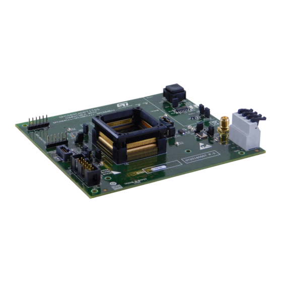
The SPC58XCADPT176S evaluation board supports STMicroelectronics SPC584BxxE7, SPC584CxxE7 and SPC58ECxxE7
microcontrollers in LQFP 176 package.
Figure 1.
SPC58XCADPT176S
Note: picture not contractual
UM2763 - Rev 1 - September 2020
www.st.com
For further information contact your local STMicroelectronics sales office.
Advertisement
Table of Contents

Related Manuals for STMicroelectronics SPC58XCADPT176S


Summary of Contents for STMicroelectronics SPC58XCADPT176S
-
Page 1: Spc58Xcadpt176S
UM2763 User manual SPC58XCADPT176S evaluation board Introduction The SPC58XCADPT176S evaluation board supports STMicroelectronics SPC584BxxE7, SPC584CxxE7 and SPC58ECxxE7 microcontrollers in LQFP 176 package. Figure 1. SPC58XCADPT176S Note: picture not contractual UM2763 - Rev 1 - September 2020 www.st.com For further information contact your local STMicroelectronics sales office. -
Page 2: Overview
UM2763 Overview Overview The SPC58XCADPT176S mini module is an evaluation board supporting STMicroelectronics SPC584BxxE7, SPC584CxxE7 and SPC58ECxxE7 microcontrollers in LQFP176 package. The mini module is designed to be connected onto the SPC58xxMB motherboard, offering a mechanism for easy customer evaluation of the supported devices, and to facilitate hardware and software development. -
Page 3: Package Contents
Overview of SPC58XCADPT176S mini module - bottom Package contents An SPC58XCADPT176S adapter package includes the following item: • SPC58XCADPT176S mini module Supported devices The SPC58XCADPT176S mini module supports the following STMicroelectronics family of microcontrollers in LQFP176 package: • SPC584CxxE7/SPC58ECxxE7 • SPC584BxxE7... -
Page 4: License Agreement
Upon breaking the seal, you and STMicroelectronics entered into the evaluation board license agreement, a copy of which is also enclosed with the evaluation board for convenience. -
Page 5: Handling Precautions
UM2763 Handling precautions Handling precautions Please take care to handle the package contents in a manner such as to prevent electrostatic discharge. Before the EVB is used or power is applied, please fully read the following sections on how to correctly configure the board. -
Page 6: Features
UM2763 Hardware description Hardware description Hardware features The SPC58XCADPT176S mini module board has the following features: • Connector for external power supplies input (5 V, 3.3 V, 1.25 V) used in stand-alone mode. • Reset button with driver and led indicator •... -
Page 7: Power And System Configuration
When the mini module is plugged onto the motherboard, power is supplied directly by the motherboard. In this setup, the external power supply input available on the mini module should NOT be used. When the SPC58XCADPT176S mini module is used as a stand-alone board, external power supplies must be used (5.0 V, 3.3 V, 1.25 V). -
Page 8: Port Configuration
Ports related jumpers Jumper Description Default Position TESTMODE settings Close Figure 4. SPC58XCADPT176S top mini module view - B2 PF[15]/EVTI connection to QSH motherboard Close Figure 4. SPC58XCADPT176S top mini module view - A2 connectors PH[11]/EVTO connection to QSH motherboard Close Figure 4. -
Page 9: Test Points
Table 6. Test points Test Point Description Position JCOMP_RxDATA_N test point Figure 4. SPC58XCADPT176S top mini module view - A3 TCK test point Figure 4. SPC58XCADPT176S top mini module view - A2 TMS_TxDATA_P test point Figure 4. SPC58XCADPT176S top mini module view... -
Page 10: Debug Configuration Jumpers
Debug configuration jumpers Connectors Description Position EVTO/ESR0 configuration jumper: • Configuration 1-2 allowed Figure 4. SPC58XCADPT176S top mini module view - A3 • Configuration 2-3 reserved PORST/ESR0 configuration jumper: • Configuration 1-2 allowed Figure 4. SPC58XCADPT176S top mini module view - A3 •... -
Page 11: Layout Overview
UM2763 Layout overview Layout overview Figure 4. SPC58XCADPT176S top mini module view UM2763 - Rev 1 page 11/24... -
Page 12: Figure 5. Spc58Xcadpt176S Bottom Mini Module View
UM2763 Layout overview Figure 5. SPC58XCADPT176S bottom mini module view UM2763 - Rev 1 page 12/24... -
Page 13: Bom
UM2763 Table 9. Item Qty Reference Part name Part description Samtec 5x2 TFM connector - 1.27 mm pitch - with Samtec TFM-105-02-L-D-WT weld tabs C1, C3, C5, C7, C16, C18, 100 nF Mult. cer. cap. 50V 0603 C20, C22, C24, C58, C103 C2, C4, C6, C8, C17, C19, C21, C23, C25, C39, C42, 10 nF... - Page 14 I.C. low voltage CMOS quad bus buffers - SO14 MC74HC1G08DTT1G CMOS single 2-input AND gate 40MHZ Quartz 40 MHz NX5032GA XTAL NDK SPC58XCADPT176S EVB for Chorus 4M CSSG20160557 R.0 MINIMODULE eTQFP176(A0A4) J1, J2, J3, J6 ,J7, J21, J23, J24, J39, J41, J46, J22, J25,...
-
Page 15: Schematics
Schematics Figure 6. Microcontroller power 5.0V_LR 3.3V_SR 5.0V_SR VDD_HV_ADR 100nF 10nF 100nF 10nF STRIP 2mm 1.25V_SR 3.3V_SR 5.0V_SR 0603 0603 0603 0603 AGND AGND VDD_HV_ADV C121 100nF 10nF 2.2uF STRIP 2mm 0603 0603 0805 AGND AST0250404 VDD_HV_IO_JTAG VDD_HV_IO_JTAG 100nF 10nF STRIP 2mm 0603 0603... -
Page 16: Figure 7. Microcontroller I/O
Figure 7. Microcontroller I/O Port pins and reset signal are routed to motherboard. High speed signals are not routed to mother board, but have test points to connect to test on mother board connector EVT signal are connected to optional jumper to be routed to mother board. -
Page 17: Figure 8. Jtag, Jtag Lfast & Sipi
Figure 8. JTAG, JTAG LFAST & SIPI JTAG interfac e JTAG/LFAST LVDS INTERFAC E 10 Pin Versio n 47nF Place CAPS as close to VDD_HV_IO_JTAG VDD_HV_IO_JTAG VDD_HV_IO_JTAG connector pins as possible but do NOT fit 47nF caps at board assembly. VDD_HV_IO_JTAG JCOMP C132... -
Page 18: Figure 9. Clock And Reset Circuit
Figure 9. Clock and reset circuit External Oscillato r External Clock Inpu t EVB-EXTAL EVB-EXTAL 3.3V_SR EXTAL 100nF EXTAL (pg3) (MCU Crystal Input) STRIP 2mm STRIP 2mm Note - External 3.3V regulator MUST be 40MHZ enabled when using Note - Internal oscillator module Pull-Up on Pin 1 XTAL... -
Page 19: Figure 10. Board Connector
Figure 10. Board connector PortA PortB PortC PortD PortE PortF PortG PortH PortI PortJ PA[0..15] PB[0..15] PC[0..15] PD[0..15] PE[0..15] PF[0..15] PG[0..15] PH[0..15] PI[0..15] PJ[0..4] (pg4) PA[0..15] (pg4) PB[0..15] (pg4) PC[0..15] (pg4) PD[0..15] (pg4) PE[0..15] (pg4,6) PF[0..15] (pg4) PG[0..15] (pg4) PH[0..15] (pg4) PI[0..15] (pg4) -
Page 20: Revision History
UM2763 Revision history Table 10. Document revision history Date Version Changes 04-Sep-2020 Initial release. UM2763 - Rev 1 page 20/24... -
Page 21: Table Of Contents
UM2763 Contents Contents Overview ................2 Package Contents. - Page 22 UM2763 List of tables List of tables Table 1. Power configuration jumpers ............7 Table 2.
- Page 23 Overview of SPC58XCADPT176S mini module - bottom ........
- Page 24 IMPORTANT NOTICE – PLEASE READ CAREFULLY STMicroelectronics NV and its subsidiaries (“ST”) reserve the right to make changes, corrections, enhancements, modifications, and improvements to ST products and/or to this document at any time without notice. Purchasers should obtain the latest relevant information on ST products before placing orders. ST products are sold pursuant to ST’s terms and conditions of sale in place at the time of order acknowledgement.
Need help?
Do you have a question about the SPC58XCADPT176S and is the answer not in the manual?
Questions and answers