Table of Contents
Advertisement
Quick Links
Introduction
This user manual explains the operation of a front panel demonstration board based on the
advanced LED controller driver STLED325 and the STM8S207K6 8-bit microcontroller as
2
the I
C master. The objective of this demonstration board is to show the features of the LED
controller driver STLED325, such as key scanning, RTC, IR decoding, standby
management, etc., for the market segment of DVD players, DVD recorders, set-top boxes,
washing machines and more, while keeping system costs as low as possible.
The system can be operated using the various front panel keys provided, as well as by
remote control. System I/O is handled completely by the STLED325 with minimal load on
the host processor.
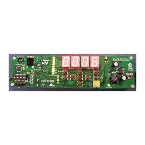
Figure 1.
The salient features of the system are:
■
4-digit, 7-segment (and decimal point) LED display
■
8 discrete LEDs
■
8 front panel keys for channel and brightness up/down, ok, menu, and standby
■
A bicolor power/standby LED
■
An interrupt LED (blinks with the interrupt)
■
A potentiometer for adjusting display brightness
■
Demonstration mode
■
Multi format remote control operation (only RC5 currently supported, but easily
extendable for various other formats.
■
Embedded in-circuit programming using a SWIM interface for the STM8S207K6
Refer to datasheet STM8S207K6; Performance line, 24 MHz. 8-bit MCU, up to 128 Kbytes
Flash, integrated EEPROM,10-bit ADC, timers, 2 UARTs, SPI, I²C, CAN.
September 2010
www.BDTIC.com/ST
STEVAL-ILL029V1 front panel demonstration board
STLED325 front panel demo
Doc ID 17476 Rev 1
UM0943
User manual
based on the STLED325
1/22
www.st.com
Advertisement
Table of Contents

Subscribe to Our Youtube Channel
Related Manuals for STMicroelectronics STEVAL-ILL029V1


Summary of Contents for STMicroelectronics STEVAL-ILL029V1
-
Page 1: Figure 1. Stled325 Front Panel Demo
UM0943 User manual STEVAL-ILL029V1 front panel demonstration board based on the STLED325 Introduction This user manual explains the operation of a front panel demonstration board based on the advanced LED controller driver STLED325 and the STM8S207K6 8-bit microcontroller as the I C master. -
Page 2: Table Of Contents
Standby mode/hot keys ........11 Appendix A STEVAL-ILL029V1 schematics ......13 Appendix B Bill of material . - Page 3 UM0943 List of figures List of figures Figure 1. STLED325 front panel demo ..........1 Figure 2.
-
Page 4: Hardware Description
Hardware description UM0943 Hardware description Figure 2. Demonstration board front view Figure 3. Demonstration board rear view Major components present on the board are (the numbers in parentheses refer to the numbers marked on the board images): ● 8 front panel keys (1): CH+, CH-, BRGHT+, BRGHT-, STBY, MENU, OK, DEMO ●... -
Page 5: Power Supply Unit
UM0943 Hardware description ● 7-segment (+dot) display (11) ● STLED325 (12) ● 32.768 kHz RTC crystal (13) ● 8 discrete LEDs for brightness (14) ● UART pinouts (15) ● Wake-up key: WAKE UP (16) ● DC buzzer for alarm function (17) ●... -
Page 6: 7-Segment (+Decimal Point) And Discrete Led Display
Hardware description UM0943 7-segment (+decimal point) and discrete LED display The board consists of 4 7-segment (+decimal point) display modules driven by the STLED325. By default, the two digits on the left display the channel information and the two digits on the right display the brightness level information. Figure 5. -
Page 7: Dip Switch/External Interface Connector
UM0943 Hardware description DIP switch/external interface connector The board consists of an 8-position DIP switch (SW2). All the switches should be in the ON position (towards circle/ON side) for the demo to work. When the device STLED325 is required to be isolated from the onboard STM8S207K6 host and controlled through an external I C host, all the switches should be moved to the OFF position. -
Page 8: Getting Started
Getting started UM0943 Getting started Package contents The STLED325 front panel demonstration board package includes: ● Demonstration board (STEVAL-ILL029V1) ● User manual (UM0943) ● Schematic ● Gerber files System requirements The system operates in standalone mode by powering externally through an external adaptor (9 V-18 V, 500 mA). -
Page 9: System Features
UM0943 System features System features Brightness adjustment through potentiometer The system is also provided with a potentiometer “BRGHT_ADJ” (R5) which can be used to vary the brightness of the LEDs by setting the output current. The brightness increases when the potentiometer is rotated clockwise and decreases with an anti-clockwise rotation. Channel number/brightness level display mode In this mode the system displays the channel number (on the far left, two 7-segment display modules) and brightness level (on the far right, two displays). -
Page 10: Set Date
System features UM0943 and BRGHT- to increase and decrease the value and CH- and CH+ to move left/right. The seconds field is taken as 0. After adjusting the time, press OK. The time is set and the system returns to channel- brightness display. -
Page 11: Standby Mode/Hot Keys
UM0943 System features The following RC operations can be done using the IR decoding feature of the STLED325: ● Device address programmed: 0x08 ● Channel up (key value: 7 and key value: 45) ● Channel down (key value: 14 and key value: 44) ●... -
Page 12: Figure 9. Entering Into Standby
System features UM0943 Figure 9. Entering into standby Figure 10. System is in standby The system can exit standby mode in any of the following ways: ● Wake-up key press ● Front panel hot key press (STBY and OK are configured as hot keys) ●... -
Page 13: Appendix Asteval-Ill029V1 Schematics
UM0943 STEVAL-ILL029V1 schematics Appendix A STEVAL-ILL029V1 schematics Figure 11. Microcontroller section Figure 12. Power supply section Doc ID 17476 Rev 1 13/22 www.BDTIC.com/ST... -
Page 14: Figure 13. Discrete Led And Seven Segment Led Section
STEVAL-ILL029V1 schematics UM0943 Figure 13. Discrete LED and seven segment LED section 14/22 Doc ID 17476 Rev 1 www.BDTIC.com/ST... -
Page 15: Figure 14. Stled325 Section
UM0943 STEVAL-ILL029V1 schematics Figure 14. STLED325 section Doc ID 17476 Rev 1 15/22 www.BDTIC.com/ST... -
Page 16: Figure 15. Keyscan Circuit Section
STEVAL-ILL029V1 schematics UM0943 Figure 15. Keyscan circuit section Figure 16. Connectors section 16/22 Doc ID 17476 Rev 1 www.BDTIC.com/ST... -
Page 17: Appendix B Bill Of Material
Table 1. Manufacturer’s ordering code / Supplier ordering Ref. des. Component description Package Manufacturer Supplier orderable part code number STM8S207K6 8-bit LQFP32 STMicroelectronics STM8S207K6T6C STMicroelectronics STM8S207K6T6C microcontroller LED controller/driver QFN32 STMicroelectronics STLED325QTR STMicroelectronics STLED325QTR U3(do not LDS3985M18TR/voltage SOT23-5L STMicroelectronics LDS3985M18TR... - Page 18 Table 1. BOM (continued) Manufacturer’s ordering code / Supplier ordering Ref. des. Component description Package Manufacturer Supplier orderable part code number 0.55 inch, 2.5 Avago Technologies U6, U7, U8, U9 HDSP5501 common anode HDSP-5501 Digi-Key 516-1212-5-ND mm pitch US Inc. DIP-8 switch C &...
- Page 19 Table 1. BOM (continued) Manufacturer’s ordering code / Supplier ordering Ref. des. Component description Package Manufacturer Supplier orderable part code number ERJ-6GEYJ472V or 3.3 Ω SMD0805 Panasonic - ECG Digi-Key P3.3KATR-ND equivalent R6,R11,R39,R4 ERJ-6GEYJ102V or 1 kΩ SMD0805 Panasonic - ECG Digi-Key P1.0KATR-ND 0,R41,R42...
- Page 20 Table 1. BOM (continued) Manufacturer’s ordering code / Supplier ordering Ref. des. Component description Package Manufacturer Supplier orderable part code number 08051A200JAT2A CAP C4,C5 25 pF SMD0805 AVX Corporation Digi-Key 478-3735-1-ND CERM Murata Electronics GRM21BF51E474ZA0 470 nF SMD0805 Digi-Key 490-1730-1-ND North America 1L or equivalent C9,C14,C16,...
-
Page 21: Revision History
UM0943 Revision history Revision history Table 2. Document revision history Date Revision Changes 03-Sep-2010 Initial release. Doc ID 17476 Rev 1 21/22 www.BDTIC.com/ST... - Page 22 Please Read Carefully: Information in this document is provided solely in connection with ST products. STMicroelectronics NV and its subsidiaries (“ST”) reserve the right to make changes, corrections, modifications or improvements, to this document, and the products and services described herein at any time, without notice.
Need help?
Do you have a question about the STEVAL-ILL029V1 and is the answer not in the manual?
Questions and answers