Table of Contents
Advertisement
Quick Links
UM0979
User manual
STEVAL-MKI109V2: eMotion motherboard for MEMS adapter boards
Introduction
The STEVAL-MKI109V2 (eMotion) is a motherboard designed to provide the user with a complete ready-to-use platform for the
demonstration of MEMS devices mounted on adapter boards.
The STEVAL-MKI109V2 uses an STM32F103RET6 microcontroller which functions as a bridge between the sensor on the
adapter board and the PC on which it is possible to use the Unico graphical user interface (GUI) downloadable from the ST
website or dedicated software routines for customized applications.
This user manual describes the hardware included with the demonstration kit and provides the information required to install the
demonstration board and how to upgrade the firmware of the microcontroller.
For details regarding the features of each sensor, please refer to the datasheet available for each individual device.
UM0979 - Rev 6 - February 2018
www.st.com/
For further information contact your local STMicroelectronics sales office.
Advertisement
Table of Contents

Subscribe to Our Youtube Channel
Related Manuals for STMicroelectronics STEVAL-MKI109V2


Summary of Contents for STMicroelectronics STEVAL-MKI109V2
- Page 1 STEVAL-MKI109V2: eMotion motherboard for MEMS adapter boards Introduction The STEVAL-MKI109V2 (eMotion) is a motherboard designed to provide the user with a complete ready-to-use platform for the demonstration of MEMS devices mounted on adapter boards. The STEVAL-MKI109V2 uses an STM32F103RET6 microcontroller which functions as a bridge between the sensor on the adapter board and the PC on which it is possible to use the Unico graphical user interface (GUI) downloadable from the ST website or dedicated software routines for customized applications.
-
Page 2: Demonstration Kit Description
UM0979 Demonstration kit description Demonstration kit description The eMotion is a complete demonstration kit that allows demonstration of both digital and analog MEMS sensors. Thanks to its DIL 24 connector, a wide range of MEMS adapter boards can be used. The block diagram of the demonstration kit is shown in Figure 1. - Page 3 UM0979 Demonstration kit description Figure 2. Top silkscreen of the eMotion kit UM0979 - Rev 6 page 3/39...
-
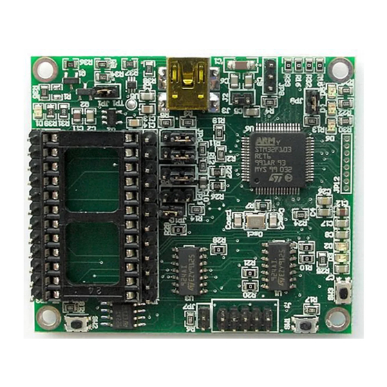
Page 4: Figure 3. Board Top View
UM0979 Demonstration kit description Figure 3. Board top view In order to use the eMotion demonstration kit, installation of a dedicated driver is required, which is included in the installation pack, together with a GUI interface which allows simple interaction with the sensor. The steps required for driver and software installation are described in the following sections. -
Page 5: Table 1. Jumper Configuration For Power-Down (Pd), Self Test (St), And High-Pass Filter Reset (Hp)
2 and ref 5) are connected to STM32 GPIOs and are available to the user. Figure 4. How to connect the DIL24 adapter board to the STEVAL-MKI109V2 shows how to properly mount the DIL24 adapter board on the STEVAL-MKI109V2 board. - Page 6 UM0979 Demonstration kit description Figure 4. How to connect the DIL24 adapter board to the STEVAL-MKI109V2 UM0979 - Rev 6 page 6/39...
-
Page 7: Emotion Board Installation
UM0979 eMotion board installation eMotion board installation The software package can be downloaded from the st.com website and includes the following directory structure: • DRIVER: it contains the installation package for the USB drivers needed to connect the eMotion board to the PC. -
Page 8: Dfu
Figure 6. Virtual COM port assignment The MEMS STEVAL-MKI109V2 demonstration board is capable of reprogramming an application through the USB, in accordance with the DFU class specification defined by the USB Implementers Forum. This capability is useful because it allows reprogramming the microcontroller directly in the field and is particularly well-suited to USB applications where the same USB connector can be used both for the standard operating mode and for the reprogramming process. -
Page 9: Dfu On Linux
UM0979 2.2.2 DFU on Linux The DFU program used for Linux operating systems is ‘dfu-util’. The procedure for Ubuntu Linux operating systems is described below. To install this program, open a terminal and write the following command (with sudo to ensure having the correct permissions): sudo apt-get install dfu-util Create a udev rules file:... -
Page 10: Supported Mems Adapter Boards
UM0979 Supported MEMS adapter boards Supported MEMS adapter boards Table 2. List of supported MEMS adapter boards below provides the complete list of supported adapter boards. Table 2. List of supported MEMS adapter boards Adapter board Device STEVAL-MKI009V1 LIS3LV02DL STEVAL-MKI013V1 LIS302DL STEVAL-MKI015V1 LIS344ALH... - Page 11 UM0979 Supported MEMS adapter boards Adapter board Device STEVAL-MKI160V1 LSM6DS3 STEVAL-MKI161V1 LSM6DS0 STEVAL-MKI163V1 LSM303C STEVAL-MKI164V1 LIS2HH12 STEVAL-MKI165V1 LPS25HB STEVAL-MKI166V1 H3LIS100DL STEVAL-MKI167V1 H3LIS200DL STEVAL-MKI168V1 IIS2DH STEVAL-MKI169V1 I3G4250D STEVAL-MKI170V1 IIS328DQ STEVAL-MKI172V1 LSM303AGR STEVAL-MKI175V1 LIS2DE12 STEVAL-MKI176V1 LSM6DS3H STEVAL-MKI177V1 LPS35HW STEVAL-MKI178V1 LSM6DSL STEVAL-MKI179V1 LIS2DW12 STEVAL-MKI180V1 LIS3DHH STEVAL-MKI181V1...
-
Page 12: Supported Commands
HyperTerminal” program available with the Windows XP operating system Create a new connection, enter a name (e.g. “STEVAL-MKI109V2”), and click “OK” In the “Connect Using” field, select the virtual COM port to which the USB port has been mapped, and click “OK”... -
Page 13: Supported Commands
UM0979 Supported commands Supported commands The firmware supports a wide range of MEMS adapters; the next section provides the complete list of supported commands (see Table 3. Supported commands list) and their description. Then, split into sections, the list of commands available for each sensor supported by the eMotion firmware is provided. - Page 14 UM0979 Supported commands Command Description Returned value *gfifostr Gyroscope “FIFO Stream” enable st 0 0 0 0 0 0 IR FC FS *gfifostf Gyroscope “Stream-to-FIFO” enable st 0 0 0 0 0 0 IR FC FS *gfifobtf Gyroscope “Bypass-to-FIFO” enable st 0 0 0 0 0 0 IR FC FS *gfifobts Gyroscope “Bypass-to-Stream”...
-
Page 15: Table 4. Returned Values For *Start Command
UM0979 Supported commands Specifically, bit#0 of the “BT” data corresponds to the status of the SW1 button on the demonstration kit board: it is set to 1 when the SW1 is pressed (otherwise 0). Bit#1 has the same behavior but is dedicated to the SW2. Before sending the *start command, the device must be out from 3-state and some registers must be configured according to user needs, therefore, *start must be preceded by a *zoff and some “Register Write”... - Page 16 UM0979 Supported commands STEVAL # (Device) Returned value STEVAL-MKI075V1 (LY3100ALH) STEVAL-MKI084V1 (LPY430AL) s t vrefH vrefL o1H o1L out1H out1L out4H out4L o2H o2L out2H out2L out5H out5L o3H o3L out3H out3L out6H out6L sw1|sw2 \\r \\n STEVAL-MKI097V1 (LPR430AL) STEVAL-MKI098V1 (LPR410AL) STEVAL-MKI106V1 (LSM303DLHC) s t A_XH A_XL A_YH A_YL A_ZH A_ZL M_XH M_XL M_YH M_YL STEVAL-MKI113V1 (LSM303DLM)
-
Page 17: Table 5. Returned Values For *Debug Command
UM0979 Supported commands Table 5. Returned values for *debug command STEVAL # (Device) Returned value STEVAL-MKI009V1 (LIS3LV02DL) STEVAL-MKI013V1 (LIS302DL) STEVAL-MKI015V1 (LIS344ALH) STEVAL-MKI087V1 (LIS331DL) STEVAL-MKI089V1 (LIS331DLH) STEVAL-MKI092V1 (LIS331HH) STEVAL-MKI105V1 (LIS3DH) STEVAL-MKI110V1 (AIS328DQ) STEVAL-MKI134V1 (LIS3DSH) STEVAL-MKI135V1 (LIS2DH) X=XXXXX Y=YYYYY Z=ZZZZZ STEVAL-MKI151V1 (LIS2DH12) STEVAL-MKI152V1 (LIS2DM) STEVAL-MKI153V1 (H3LIS331DL) STEVAL-MKI158V1 (AIS3624DQ) - Page 18 UM0979 Supported commands STEVAL # (Device) Returned value STEVAL-MKI120V1 (LPS331AP) STEVAL-MKI142V1 (LPS25H) STEVAL-MKI165V1 (LPS25HB) P=PPPPP T=TTTTT STEVAL-MKI177V1 (LPS35HW) STEVAL-MET001V1 (LPS22HB) STEVAL-MKI122V1 (LSM330DLC) STEVAL-MKI123V1 (LSM330D) STEVAL-MKI160V1 (LSM6DS3) AX=XXXXX AY=YYYYY AZ=ZZZZZ GX=XXXXX GY=YYYYY GZ=ZZZZZ STEVAL-MKI161V1 (LSM6DS0) STEVAL-MKI176V1 (LSM6DS3H) STEVAL-MKI178V1 (LSM6DSL) STEVAL-MKI124V1 (10AXISMODULE) AX=XXXXX AY=YYYYY AZ=ZZZZZ MX=XXXXX MY=YYYYY MZ=ZZZZZ GX=XXXXX GY=YYYYY GZ=ZZZZZ P=PPPPP T=TTTTT STEVAL-MKI141V2 (HTS221)
- Page 19 UM0979 Supported commands address of the register and the data to be written. For example, to write 0xC7 to the register at address 0x20, the user issues the command *w20C7. Gyroscope register read The *grAA command allows the contents of the gyroscope registers in the demonstration kit board to be read. AA, expressed as hexadecimal value and written in upper case, represents the address of the register to be read.
- Page 20 UM0979 Supported commands For example, to read the register at address 0x20, the user issues the command *hr20, which returns, e.g., HR20h10h. Humidity sensor register write The *hwAADD command allows writing to the contents of the humidity sensor registers in the demonstration kit board.
- Page 21 UM0979 Supported commands Accelerometer Dynamic Stream mode enable The *fifodstr command enables the accelerometer Dynamic Stream mode. Gyroscope FIFO reset enable The *gfiforst command enables the gyroscope FIFO reset mode. Gyroscope FIFO mode enable The *gfifomde command is used to enable the gyroscope FIFO mode. Gyroscope FIFO Stream mode enable The *gfifostr command is used to enable the gyroscope FIFO stream mode.
- Page 22 UM0979 Supported commands Pressure sensor FIFO mode enable The *pfifomde command is used to enable the pressure sensor FIFO mode. Pressure sensor FIFO Stream mode enable The *pfifostr command is used to enable the pressure sensor FIFO stream mode. Pressure sensor Stream-to-FIFO mode enable The *pfifostf command enables the pressure sensor Stream-to-FIFO mode.
-
Page 23: Digital Output Accelerometers: Supported Commands
UM0979 Supported commands 4.2.2 Digital output accelerometers: supported commands Table 6. Digital output accelerometers: supported commands list below lists the commands supported by the devices/demonstration boards including a digital output accelerometer. Table 6. Digital output accelerometers: supported commands list Command Description Returned value *setdbXXXVY... -
Page 24: Analog Output Accelerometers: Supported Commands
UM0979 Supported commands 4.2.3 Analog output accelerometers: supported commands Table 7. Analog output accelerometers: supported commands list below lists the commands supported by the devices/demonstration boards including an analog output accelerometer. Table 7. Analog output accelerometers: supported commands list Command Description Returned value *setdbXXXVY... -
Page 25: Digital Output Gyroscopes: Supported Commands
UM0979 Supported commands 4.2.4 Digital output gyroscopes: supported commands Table 8. Digital output gyroscopes: supported commands list below lists the commands supported by the devices/ demonstration boards including a digital output gyroscope. Table 8. Digital output gyroscopes: supported commands list Command Description Returned value... -
Page 26: Analog Output Gyroscopes: Supported Commands
UM0979 Supported commands 4.2.5 Analog output gyroscopes: supported commands Table 9. Analog output gyroscopes: supported commands list below lists the commands supported by the devices/demonstration boards including an analog output gyroscope. Table 9. Analog output gyroscopes: supported commands list Command Description Returned value *setdbXXXVY... -
Page 27: Digital Output Magnetometers: Supported Commands
UM0979 Supported commands 4.2.6 Digital output magnetometers: supported commands Table 10. Digital output magnetometers: supported commands list below lists the commands supported by the devices/demonstration boards including a digital output magnetometer. Table 10. Digital output magnetometers: supported commands list Command Description Returned value *setdbXXXVY... -
Page 28: Digital Output Pressure Sensors: Supported Commands
UM0979 Supported commands 4.2.7 Digital output pressure sensors: supported commands Table 11. Digital output pressure sensors: supported commands list below lists the commands supported by the devices/demonstration boards including a digital output pressure sensor. Table 11. Digital output pressure sensors: supported commands list Command Description Returned value... -
Page 29: Digital Output Humidity Sensors: Supported Commands
UM0979 Quick start 4.2.8 Digital output humidity sensors: supported commands Table 11. Digital output pressure sensors: supported commands list below lists the commands supported by the devices/demonstration boards including a digital output humidity sensor. Table 12. Digital output humidity sensors: supported commands list Command Description Returned value... -
Page 30: Schematic Diagrams
Schematic diagrams The schematic diagrams of the eMotion demonstration kit are shown in Figure 7. eMotion board (power supply and USB) Figure 8. STEVAL-MKI109V2 eMotion board (STM32F103RET6 and connectors). Figure 7. eMotion board (power supply and USB) UM0979 - Rev 6... - Page 31 UM0979 Schematic diagrams Figure 8. STEVAL-MKI109V2 eMotion board (STM32F103RET6 and connectors) PA14/JTCK/SWCLK Vdd1 JTCK_SWCLK PA15/JTDI Vss1 JTDI PC10 PB11 Gled CS_RF PC11 PB10 Rled IRQ_RF PC12 PB2/BOOT1 ST_u BOOT1 PB1/ADC9 PD_u OUT2_u PB3/JTDO PB0/ADC8 JTDO OUT1_u PB4/JNTRST PC5/ADC15 JNTRST OUT6_u...
-
Page 32: Bill Of Materials
Bill of materials Bill of materials The bill of materials for the eMotion demonstration kit is provided in Table 13. Bill of materials for STEVAL- MKI109V2 below. Table 13. Bill of materials for STEVAL-MKI109V2 Designator Description Comment Footprint Capacitor 10 µF... - Page 33 UM0979 Bill of materials Designator Description Comment Footprint CON2 Header 1x2 2 mm CON2 Header 1x2 2 mm JP10 CON2 Header 1x2 2 mm Osc1 Ceramic SMD crystal 3.2X2.5 mm 16 MHz Ceramic SMD Crystal 3.2x2.5 mm BC817-25 BC817 SOT-23 BC817-25 BC817 SOT-23...
- Page 34 UM0979 Bill of materials Designator Description Comment Footprint Resistor 1.5 kΩ 0805 Resistor 22 Ω 0805 Resistor 22 Ω 0805 Resistor 47 kΩ 0805 SMT SWITCH SMT SWITCH SMT SWITCH TS924 TS924 TS924 Component_1 lds3985xx30 SOT23-5 TS924 TS924 TS924 TS922 TS922 SO8_2 USBLC6-2P6...
-
Page 35: Revision History
Added: Section 2.2.2: DFU on Linux, Section 2.2.3: DFU on Mac OS, and Section 4.2.8: Digital output humidity sensor: supported commands Removed: STEVAL-MKI109V1 Added Figure 4: How to connect the DIL24 adapter board to the STEVAL-MKI109V2 Updated version of VCP Driver to V.1.4.0 in Section 2.1: Hardware installation (Windows platforms) Updated reference to version of firmware in use to lower than V3.0.0 in Section 2.2:... -
Page 36: Table Of Contents
UM0979 Contents Contents Demonstration kit description............2 eMotion board installation . - Page 37 Bill of materials for STEVAL-MKI109V2........
- Page 38 How to connect the DIL24 adapter board to the STEVAL-MKI109V2 .......
- Page 39 IMPORTANT NOTICE – PLEASE READ CAREFULLY STMicroelectronics NV and its subsidiaries (“ST”) reserve the right to make changes, corrections, enhancements, modifications, and improvements to ST products and/or to this document at any time without notice. Purchasers should obtain the latest relevant information on ST products before placing orders. ST products are sold pursuant to ST’s terms and conditions of sale in place at the time of order acknowledgement.
Need help?
Do you have a question about the STEVAL-MKI109V2 and is the answer not in the manual?
Questions and answers