Table of Contents
Advertisement
Quick Links
UM2868
User manual
SPC570SADPT100S evaluation board
Introduction
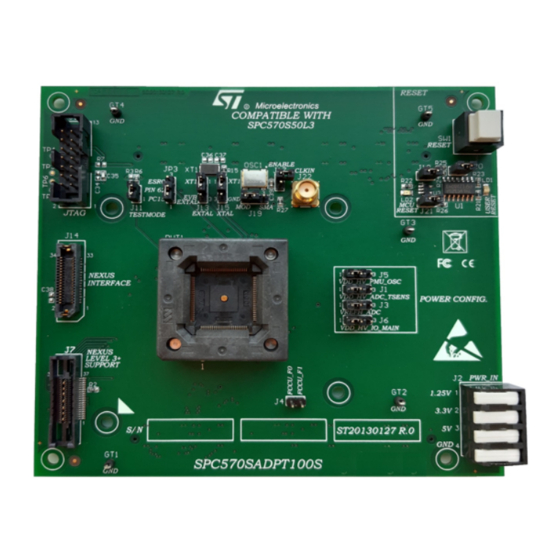
The SPC570SADPT100S mini module is an evaluation board supporting STMicroelectronics SPC570S50L3 microcontroller
device in eTQFP100 package.
Figure 1.
SPC570SADPT100S
UM2868 - Rev 1 - May 2021
www.st.com
For further information contact your local STMicroelectronics sales office.
Advertisement
Table of Contents

Subscribe to Our Youtube Channel
Related Manuals for STMicroelectronics SPC570SADPT100S


Summary of Contents for STMicroelectronics SPC570SADPT100S
- Page 1 UM2868 User manual SPC570SADPT100S evaluation board Introduction The SPC570SADPT100S mini module is an evaluation board supporting STMicroelectronics SPC570S50L3 microcontroller device in eTQFP100 package. Figure 1. SPC570SADPT100S UM2868 - Rev 1 - May 2021 www.st.com For further information contact your local STMicroelectronics sales office.
-
Page 2: Overview
The SPC570SADPT100S mini module is an evaluation board supporting STMicroelectronics SPC570S50L3 microcontroller device in eTQFP100 package. The SPC570SADPT100S mini module is designed to be connected onto the SPC58xxMB motherboard, offering a mechanism for easy customer evaluation of the SPC570S50xx family of device, and to facilitate hardware and software development. -
Page 3: Supported Devices
UM2868 Supported devices Figure 3. Overview of SPC570SADPT100S - bottom Supported devices The SPC570SADPT100S supports the following STMicroelectronics family of microcontrollers in eTQFP100: • SPC570S50L3 UM2868 - Rev 1 page 3/30... -
Page 4: License Agreement
Upon breaking the seal, you and STMicroelectronics entered into the evaluation board license agreement, a copy of which is also enclosed with the evaluation board for convenience. -
Page 5: Handling Precautions
UM2868 Handling precautions Handling precautions Please take care to handle the package content in order to prevent electrostatic discharge. Before the EVB is used or power is applied, please fully read the following sections on how to correctly configure the board. Failure to correctly configure the board may cause irreparable component, MCU or EVB damage. UM2868 - Rev 1 page 5/30... -
Page 6: Features
It can be used as a stand-alone board by providing external power supplies input (5 V, 3.3 V, 1.25 V) • Reset button with driver and led indicator • SPC570SADPT100S has the socket for device in eTQFP100 package • Debug ports: –... -
Page 7: Hardware And Jumper Setting
NOT be used. When the SPC570SADPT100S mini module is used as a stand-alone board , the external power supplies must be used (5 V, 3.3 V, 1.25 V). -
Page 8: Jtag/Lfast Lvds/ Sipi Interface Configuration
Port related jumpers Jumper Description Default Position TESTMODE connection configuration: • Open: TESTMODE not connected Close (default pull- Figure 10. Overview of SPC570SADPT100S • Closed: TESTMODE connected to: down) mini module - top – A2 – R6 Mounted: pulldown (default) –... -
Page 9: System Clock Configuration
Position EXTAL connectionconfiguration: Figure 10. Overview of 1-2 (XT1 • 1-2: EXTAL connected to 40 MHz cristal clock source SPC570SADPT100S mini module - top – pin2) • 2-3: EXTAL connected to EXTAL EVB clock source XTAL connectionconfiguration: Figure 10. Overview of 1-2 (XT1 •... -
Page 10: Reset Circuit
The mini module evaluation board has the following debug connectors: Table 4. Connectors Conn ector Description Position Figure 10. Overview of SPC570SADPT100S mini module 14-pin header connector for JTAG port - top – A1 Figure 10. Overview of SPC570SADPT100S mini module 34-pin SAMTEC connector for Nexus 2 - top –... -
Page 11: Table 5. Jtag Header 2X7 Pins Connector Pinout
UM2868 Connectors Table 5. JTAG Header 2x7 pins connector pinout Pin number Signal EVTI N.C. PORST VDD_HV_IO_MAIN EVTO N.C. The following picture shows the NEXUS SAMTEC ASP-137973-01 connector schema. Figure 6. NEXUS SAMTEC ASP-137973-01 UM2868 - Rev 1 page 11/30... -
Page 12: Table 6. Nexus Samtec Asp-137973-01 Connector Pinout
UM2868 Connectors The following table shows the NEXUS SAMTEC ASP-137973-01 connector pinout. Table 6. NEXUS SAMTEC ASP-137973-01 connector pinout Pin number Signal N.C. 3.3 V N.C. TX1P TX1N JCOMP N.C. N.C. N.C. EVTI EVTO N.C. PORST N.C. ESR0 N.C. N.C. N.C. -
Page 13: Table 7. Nexus Level 3+ Connector Pinout
UM2868 Connectors Figure 7. AURORA schema The following picture shows the Nexus level 3+ connector pinout. Table 7. Nexus level 3+ connector pinout Pin number Signal Not connected Not connected Not connected Not connected Not connected TRACE_D2_P Not connected TRACE_D2_N Not connected TRACE_D0_P Not connected... -
Page 14: Figure 8. Fccu Connector Schema
UM2868 Connectors Pin number Signal TRACE_D0_N Not connected TRACE_CLK_P Not connected TRACE_CLK_N Not connected TRACE_D1_P Not connected TRACE_D1_N Not connected TRACE_D3_P Not connected TRACE_D3_N Not connected Not connected Not connected The following figure shows the FCCU (Fault Collection and Control Unit) connector schema. Figure 8. -
Page 15: Test Points
3.3 V Test points Several test points of different shape and functionality are scattered around the SPC570SADPT100S evaluation board to allow easy access to MCU and reference signals. This chapter summarizes and describes the available test points. Test points are listed and detailed in the following table. - Page 16 Test points Test Point Description Position TCK test point (JTAG) Figure 10. Overview of SPC570SADPT100S mini module - top – A1 TMS test point (JTAG) Figure 10. Overview of SPC570SADPT100S mini module - top – A1 TDI test point (JTAG) Figure 10.
-
Page 17: Layout Overview
UM2868 Layout overview Layout overview Figure 10. Overview of SPC570SADPT100S mini module - top UM2868 - Rev 1 page 17/30... -
Page 18: Figure 11. Overview Of Spc570Sadpt100S Mini Module - Bottom
UM2868 Layout overview Figure 11. Overview of SPC570SADPT100S mini module - bottom UM2868 - Rev 1 page 18/30... -
Page 19: Bom
UM2868 Table 11. Item Reference Value Options Description CCERSMD105-08 Mult. Cer. cap. 1μF 50V SMD 0805 C2, C5, C8, C10, C13, C15, CCERSMD104-06 Mult. Cer. cap. 100nF C19, C26, 50V SMD 0603 C29, C32, C3, C9, CCERSMD102-06 Mult. Cer. cap. 100V SMD 0603 CCERSMD474-08 Mult. - Page 20 UM2868 Item Reference Value Options Description Conn. SMD TYCO , vertical, female, 38P TYCO-5767054-1 5767054-1 MICTOR - GND Pin Lenght 2.74mm J11, J18, STRIP2PM STRIP2PM Close Male Strip 2 poles J20, J21 3M Conn Flat Male 14 pins, M.14.180 LP-3M N2514-6002RB straight - Pitch 2.54mm...
- Page 21 UM2868 Item Reference Value Options Description I.C. Low Voltage 74LVC125AMTR- 74LVC125AMTR CMOS Quad Bus Buffers - SO14 I.C. Single 2-Input 74V1G08-SMD 74V1G08STR and Gate - SMD SOT23-5L Quartz 40MHz Q40MHZ- 40 MHz SMD NX5032GA SMD-5032 XTAL NDK UM2868 - Rev 1 page 21/30...
-
Page 22: Schematic
0603 VDD_HV_PMU_OSC VDD_HV_IO_W0 VDD_HV_IO_E0 I/O (3.3v - 5V) VDD_HV_IO_N0 VDD_HV_IO_MAIN CLOSE TO PIN 20 MOUNTED MOUNTED MOUNTED VDD_HV_IO_MAIN VDD_HV_IO_N1 STRIP3PM SPC570SADPT100S Power Pins 100nF 100nF 1nF DNP 100nF 1nF DNP 100nF 1nF DNP DEFAULT 2.2uF 2.2uF 2.2uF 2.2uF 100V 100V... -
Page 23: Figure 13. Signals
Figure 13. Signals S i g n a l s PD[0..15] TP3 TP4 TP5 TP6 PD[0..15] DUT1B PD[0] PD[1] PD[2] PD[3] PA[0..15] PA[0..15] PD[4] PD[5] PD[6] PD[7] PD[8] PA[0] PD[9] PA[1] PD10 PD[10] PA[2] PD11 PD[11] PA[3] PD12 PD[12] PA[4] PD13 PD[13] PA[5]... -
Page 24: Figure 14. Reset, Jtag, Nexus Level 3+ Support, Nexus Interface And Crystal Oscillator
Figure 14. Reset, JTAG, Nexus level 3+ support, Nexus interface and crystal oscillator VDD_HV_IO_MAIN Jtag interface Re s e t , J TAG, Ne x u s le ve l 3 + s u p p or t , Ne x u s In t e r fa c e a n d Cr y s t a l Os c illa t or NOT MOUNTED 0R DNP JTAG Connector... -
Page 25: Figure 15. Daughte Card To Motherboard Connectors
Figure 15. Daughte card to motherboard connectors DAUGHTER CARD TO MOTHERBOARD CONNECTORS PortB PortC PortD PortA PortE PA[0..15] PB[0..15] PC[0..15] PD[0..15] PE[0..15] PA[0..15] PB[0..15] PC[0..15] PD[0..15] PE[0..15] PA10 PB10 PC10 PD10 PE10 PA11 PB11 PC11 PD11 PE11 PA12 PB12 PC12 PD12 PE12 PA13... -
Page 26: Revision History
UM2868 Revision history Table 12. Document revision history Date Version Changes 24-May-2021 Initial release. UM2868 - Rev 1 page 26/30... -
Page 27: Table Of Contents
UM2868 Contents Contents Overview ................2 Supported Devices . - Page 28 UM2868 List of tables List of tables Table 1. Power supplies configuration jumpers............7 Table 2.
- Page 29 Overview of SPC570SADPT100S mini module - bottom........
- Page 30 IMPORTANT NOTICE – PLEASE READ CAREFULLY STMicroelectronics NV and its subsidiaries (“ST”) reserve the right to make changes, corrections, enhancements, modifications, and improvements to ST products and/or to this document at any time without notice. Purchasers should obtain the latest relevant information on ST products before placing orders. ST products are sold pursuant to ST’s terms and conditions of sale in place at the time of order acknowledgement.
Need help?
Do you have a question about the SPC570SADPT100S and is the answer not in the manual?
Questions and answers