Table of Contents
Advertisement
Quick Links
UM3024
User manual
Getting started with the STEVAL-L3751V12 evaluation board based on DC-DC
converter buck regulator with L3751 controller
Introduction
The 6 to 75 V wide input voltage range
STEVAL-L3751V12
synchronous buck evaluation board features an extreme voltage
conversion ratio over switching frequency.
The board provides a regulated 5 V output at 230 kHz switching frequency. The output voltage can be easily set to 12 V using a
jumper connector. Different voltage output can be selected by changing a resistor to a lower V
range.
IN
The
STEVAL-L3751V12
is a 100 W demo board. The default maximum current is set to 15 A. It can be easily selected by
changing a resistor.
The evaluation board is based on the
L3751
synchronous buck controller, which implements the voltage mode in a VQFN
package with internal compensation to minimize the design complexity and size.
The diode emulation (DEM) implements the pulse-skipping mode, which maximizes the efficiency at light-load with a controlled
output voltage ripple.
The forced PWM (FPWM) over-the-load range makes the switching frequency constant and minimizes the output voltage ripple.
The power good open collector output validates the regulated output voltage for monitoring. It implements the output voltage
sequencing for digital ICs during the power-up phase.
The embedded gate driver is designed for standard Vth MOSFET and minimizes the number of external components.
The embedded protections, such as the output overcurrent, the input voltage UVLO, the internal voltage monitoring, and the
thermal shutdown at 150°C degrees, feature a controlled and safe operation for critical environments in telecom, networking,
and industrial applications.
You can use the
eDesignSuite
software tool to configure the
L3751
buck converter and satisfy the application requirements.
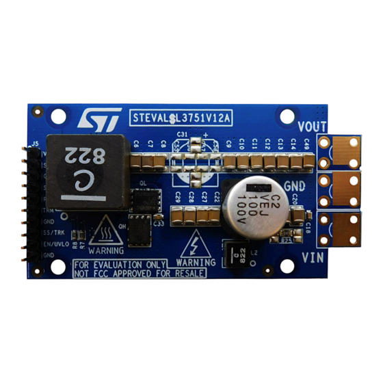
Figure 1.
STEVAL-L3751V12 evaluation board (top view)
Figure 2.
STEVAL-L3751V12 evaluation board (bottom view)
UM3024 - Rev 1 - October 2022
www.st.com
For further information contact your local STMicroelectronics sales office.
Advertisement
Table of Contents

Subscribe to Our Youtube Channel
Related Manuals for STMicroelectronics STEVAL-L3751V12


Summary of Contents for STMicroelectronics STEVAL-L3751V12
-
Page 1: Figure 1. Steval-L3751V12 Evaluation Board (Top View)
UM3024 User manual Getting started with the STEVAL-L3751V12 evaluation board based on DC-DC converter buck regulator with L3751 controller Introduction The 6 to 75 V wide input voltage range STEVAL-L3751V12 synchronous buck evaluation board features an extreme voltage conversion ratio over switching frequency. -
Page 2: Getting Started
UM3024 Getting started Getting started Safety instructions Caution: This board has to be used only by skilled technical personnel who are suitably qualified and familiar with the installation, use, and maintenance of power electronic systems. The same personnel must be aware of and must apply national accident prevention rules. -
Page 3: How To Use The Board
UM3024 How to use the board How to use the board STEVAL-L3751V12 is configured through the L3751 with adjustable V . The board is set to deliver a 5 V or 12 V output voltage (see Section 3.4 Signal manager - J5) with F = 230 kHz. -
Page 4: Connectors And Test Points
Pin 5 - PGOOD: output signal. It is an open collector. It is short to GND once V is out of the regulator windows (±8%). Otherwise, it is short to the external pull-up voltage. In the STEVAL-L3751V12, it is pulled up to the V pin. -
Page 5: Input Emi Filter
UM3024 Input EMI filter Input EMI filter STEVAL-L3751V12 is compliant with CISPR16-4-2. An input filter helps to reduce EMI. This filter consists of: • a double pi filter with an inductor (L2); • a ferrite bead (L5); • MLCC capacitors (C18, C19, C20, and C30);... -
Page 6: Board Setting Capability
UM3024 Board setting capability Board setting capability STEVAL-L3751V12 overcurrent limit is set to 18 A (average) through R5. Increasing or decreasing this resistor, it is possible to increase or decrease the current limit (check the datasheet or eDesignSuite for further details). -
Page 7: Edesignsuite
UM3024 eDesignSuite eDesignSuite eDesignSuite suite software tool helps you to configure ST products for power conversion applications. You can use it to customize a PFC controller for a specific application. Start by entering the main specifications for your design. Then, generate an automatic design or follow a sequential process to build a highly customized design. -
Page 8: Pcb Layout
PCB layout STEVAL-L3751V12 is a 4-layer PCB with 1-oz copper thickness for external layers and 0.5-oz for internal layers. Figure 3. STEVAL-L3751V12 PCB layout (1 of 4) Figure 4. STEVAL-L3751V12 PCB layout (2 of 4) UM3024 - Rev 1 page 8/24... -
Page 9: Figure 5. Steval-L3751V12 Pcb Layout (3 Of 4)
UM3024 PCB layout Figure 5. STEVAL-L3751V12 PCB layout (3 of 4) Figure 6. STEVAL-L3751V12 PCB layout (4 of 4) UM3024 - Rev 1 page 9/24... -
Page 10: Performance Waveforms
UM3024 Performance waveforms Performance waveforms soft start • Green = V • Blue = V • Yellow = switching node • Violet = PGOOD Figure 7. = 48 V, V = 12 V at no load Figure 8. = 48 V, V = 5 V at no load Figure 10. -
Page 11: Figure 11. Vin = 48 V, Vout
UM3024 Performance waveforms Figure 12. = 48 V, V = 12 V at no load Figure 11. = 48 V, V = 5 V at no load Start-up with V in short Figure 14. = 48 V Figure 13. = 48 V - hiccup ripple Figure 16. -
Page 12: Figure 18. Vin = 48 V, Vout = 12.2 V, I
UM3024 Performance waveforms Figure 17. = 48 V, V = 12.2 V, I = 0 A Figure 18. = 48 V, V = 12.2 V, I = 15 A Load transient Figure 20. = 24 V, V = 12.2 V, I = 5-15 A Figure 19. -
Page 13: Figure 23. Efficiency Curve In Dem
UM3024 Performance waveforms Figure 23. Efficiency curve in DEM - V = 5 V, Figure 24. Efficiency curve in DEM - V = 12 V, = 230 kHz = 230 kHz UM3024 - Rev 1 page 13/24... -
Page 14: Thermal Parameters
UM3024 Thermal parameters Thermal parameters Figure 25. Thermal performance (top view) - V Figure 26. Thermal performance (bottom view) - V 48 V, V = 12 V, I = 10 A, 230 KHz, 200 LFM air = 48 V, V = 12 V, I = 10 A, 230 KHz, 200 LFM flow... -
Page 15: Schematic Diagrams
Schematic diagrams Figure 29. STEVAL-L3751V12 circuit schematic EM I Fi l t er I NPUT DECOUPLI NG L5 NC 8.2uH 10nF 10uF 100uF 10uF 10uF 10uF 10uF 10uF 10uF 10uF 10uF 10uF 10uF 10uF PGND 0.1uF BAT46-SOD-323 ZC1818-822 10nF PGOOD... -
Page 16: Bill Of Materials
UM3024 Bill of materials Bill of materials Table 1. STEVAL-L3751V12 bill of materials Item Q.ty Ref. Part/value Description Manufacturer Order code 0.1 µF 0603 (1608 Ceramic metric) 100 V ±10% Murata GRM188R72A104KA35D capacitor 100 nF 0603 (1608 Ceramic metric) 35 V ±10%... - Page 17 UM3024 Bill of materials Item Q.ty Ref. Part/value Description Manufacturer Order code 100 V, 150 mA BAT46WFILM,SOT SMD general BAT46WFILM purpose signal Schottky diode FS1, FS2, FS4 Not mounted 10 pins x 2.54 mm Strip TE connectivity 1872200 XGL-5050-822MEC Power coil Coilcraft XGL-5050-822MEC ind_XGL_5050...
-
Page 18: Board Versions
STEVAL-L3751V12 versions PCB version Schematic diagrams Bill of materials STEVAL$L3751V12A STEVAL$L3751V12A schematic diagrams STEVAL$L3751V12A bill of materials 1. This code identifies the STEVAL-L3751V12 evaluation board first version. It is printed on the board PCB. UM3024 - Rev 1 page 18/24... -
Page 19: Regulatory Compliance Information
UM3024 Regulatory compliance information Regulatory compliance information Formal Notice Required by the U.S. Federal Communications Commission FCC NOTICE This kit is designed to allow: (1) Product developers to evaluate electronic components, circuitry, or software associated with the kit to determine whether to incorporate such items in a finished product and (2) Software developers to write software applications for use with the end product. -
Page 20: Revision History
UM3024 Revision history Table 3. Document revision history Date Revision Changes 04-Oct-2022 Initial release. UM3024 - Rev 1 page 20/24... -
Page 21: Table Of Contents
UM3024 Contents Contents Getting started ..............2 Safety instructions. -
Page 22: List Of Tables
STEVAL-L3751V12 bill of materials ........ -
Page 23: List Of Figures
STEVAL-L3751V12 evaluation board (bottom view)........ - Page 24 IMPORTANT NOTICE – READ CAREFULLY STMicroelectronics NV and its subsidiaries (“ST”) reserve the right to make changes, corrections, enhancements, modifications, and improvements to ST products and/or to this document at any time without notice. Purchasers should obtain the latest relevant information on ST products before placing orders. ST products are sold pursuant to ST’s terms and conditions of sale in place at the time of order acknowledgment.
Need help?
Do you have a question about the STEVAL-L3751V12 and is the answer not in the manual?
Questions and answers