Table of Contents
Advertisement
Quick Links
UM2381
User manual
Getting started with the evaluation kit for automotive rear lights with pattern
animations based on ALED1262ZT and STM8AF6266
Introduction
The
STEVAL-LLL002V1
evaluation kit consists of the STEVAL-LLL002M1 main board and the STEVAL-LLL002D1 USB-UART
bridge.
It has been designed to test and evaluate ALED1262ZT performance.
The STEVAL-LLL002M1 is a LED array driver system evaluation board with local dimming and diagnostics for automotive
applications. It is based on the
ALED1262ZT
12-channel LED driver controlled through the
STM8AF6266
microcontroller I²C
interface.
A 48 red LED matrix is driven by four ALED1262ZT LED drivers.
The on-board
A7986A
DC-DC converter, accepting standard adapter input voltages with reverse polarity protection, provides
the voltages and power for the board operation.
The STEVAL-LLL002V1 evaluation kit jumpers simulate LED open circuit faults and the 4-pin SWIM connector is used to debug
and develop the STM8AF6266 microcontroller firmware.
The evaluation kit can operate in bus driven mode (BDM), standalone mode (SAM) and GUI mode.
In the bus driven mode, the board is controlled via on-board push buttons and potentiometers. Commands to the ALED1262ZT
driver are sent by STM8A microcontroller over I²C bus.
In the standalone mode, the STEVAL-LLL002V1 evaluation kit is not controlled by the MCU and you can select two possible
output configurations using OTP ½ SPDT switch (SW2).
In the GUI mode, the board is connected to a PC via USB-UART bridge and you can observe and control various features of the
driver through the graphical user interface.
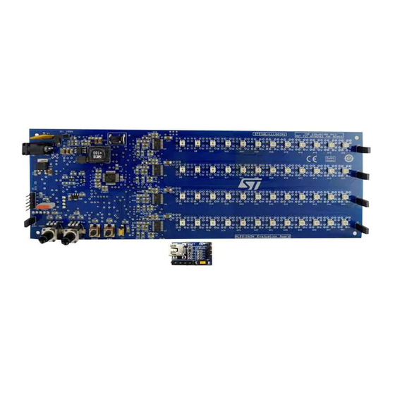
Figure 1.
STEVAL-LLL002V1 evaluation kit
UM2381 - Rev 1 - June 2019
www.st.com
For further information contact your local STMicroelectronics sales office.
Advertisement
Table of Contents

Related Manuals for STMicroelectronics STEVAL-LLL002V1


Summary of Contents for STMicroelectronics STEVAL-LLL002V1
-
Page 1: Figure 1. Steval-Lll002V1 Evaluation Kit
In the bus driven mode, the board is controlled via on-board push buttons and potentiometers. Commands to the ALED1262ZT driver are sent by STM8A microcontroller over I²C bus. In the standalone mode, the STEVAL-LLL002V1 evaluation kit is not controlled by the MCU and you can select two possible output configurations using OTP ½ SPDT switch (SW2). -
Page 2: Hardware Description
UM2381 Hardware description Hardware description STEVAL-LLL002M1 main board The STEVAL-LLL002M1 evaluation board includes four ALED1262ZT LED drivers, an 8-bit automotive grade MCU, a SWIM connector to program the MCU, 48 red LEDs, push buttons to switch modes, and potentiometers to control brightness and speed. The on-board A7986A DC-DC converter, accepting standard adapter input voltages (12 –... -
Page 3: Steval-Lll002D1 Usb-Uart Bridge
I²C providing 18 V (±1 V) to be applied at the corresponding chip select (CS) pin. Note: For more information please refer to the ALED1262ZT datasheet on www.st.com. STEVAL-LLL002D1 USB-UART bridge STEVAL-LLL002V1 evaluation kit is also equipped with a USB-UART bridge for the communication between PC and microcontroller. Figure 4. -
Page 4: Steval-Lll002V1 Key Devices
UM2381 Evaluation kit block diagram Evaluation kit block diagram Figure 6. STEVAL-LLL002V1 block diagram STEVAL-LLL002V1 key devices STEVAL-LLL002V1 main devices are: • A7986A: a high efficiency step down 250 kHz (programmable up to 1 MHz) switching regulator with max. 3 A DC output current. -
Page 5: Steval-Lll002V1 Connections
UM2381 STEVAL-LLL002V1 connections STEVAL-LLL002V1 connections Power supply STEVAL-LLL002V1 evaluation kit is powered by standard 12–24 V DC power adapter. The power source must deliver sufficient current depending on the input voltage for proper functioning. Reverse voltage protection and input surge protection are provided to avoid any damage. -
Page 6: Operation Modes
UM2381 Operation modes Operation modes Bus driven mode In this mode, STEVAL-LLL002V1 is controlled via on-board push buttons and potentiometers. Commands to the ALED1262ZT LED driver are sent by STM8AF6266 microcontroller through I²C interface. After DC input is applied for the first time, the board goes into free running mode and displays all patterns and modes, one after another. -
Page 7: 13. Error Detection
The defective LED is signaled by switching on the adjacent LED. Table 2. STEVAL-LLL002V1 error detection mode Jumper Error in LED Shown on LED Figure 7. STEVAL-LLL002V1 evaluation kit: error detection mode (J6 and J7 removed) UM2381 - Rev 1 page 7/29... -
Page 8: Standalone Mode (Sam)
In standalone mode configuration, the device is not controlled by the MCU or a controller board. You can select two possible output configurations using OTP ½ SPDT switch (SW2). Figure 8. STEVAL-LLL002V1 evaluation kit: standalone mode (configuration 1) Figure 9. STEVAL-LLL002V1 evaluation kit: standalone mode (configuration 2) 3.2.1... -
Page 9: Gui Setup
The GUI appears in your program list. Step 2. If the VCP driver is not installed, install it from ...\Program Files\ STMicroelectronics\LED Driver Demo \ST VCP Driver. A 32-bit version and a 64-bit version are included in the setup. On launching the GUI, the initial screen appears as shown below. -
Page 10: Modes
UM2381 GUI mode 3.3.3 Modes 3.3.3.1 Basic mode STSW-LLL002GUI basic mode mainly features: • Replication of on-board control buttons to select different modes from the GUI • Buttons to enable/disable on-board push buttons • Open circuit error detection with different frequencies •... -
Page 11: Figure 12. Aled1262Zt Configuration Register
Frame programming to display any arbitrary pattern up to 20 frames with variable transition speed • Four preconfigured patterns for quick visualization of frame programming mode on the STEVAL-LLL002V1 evaluation kit Frame programming displays user defined patterns in round robin sequence on the evaluation board. This mode contains a set of 20 (maximum) independent frames and each frame represents one instance of the board LEDs. -
Page 12: Figure 14. Stsw-Lll002Gui Frame Programming Mode
UM2381 GUI mode Figure 14. STSW-LLL002GUI frame programming mode 3.3.3.3.1 Frame design A frame on the STSW-LLL002GUI represents LEDs on the evaluation board in a similar fashion. There are a maximum of 20 frames (00 to 19) to be set using [Set Frame Count]. To design the frames and demonstrate them on the evaluation board follow the procedure below. -
Page 13: Figure 16. Stsw-Lll002Gui Frame Programming Mode Preset2
UM2381 GUI mode Figure 16. STSW-LLL002GUI frame programming mode Preset2 Figure 17. STSW-LLL002GUI frame programming mode Preset3 UM2381 - Rev 1 page 13/29... -
Page 14: Figure 18. Stsw-Lll002Gui Frame Programming Mode Preset4
UM2381 GUI mode Figure 18. STSW-LLL002GUI frame programming mode Preset4 UM2381 - Rev 1 page 14/29... -
Page 15: Schematic Diagrams
Schematic diagrams Figure 19. STEVAL-LLL002M1 circuit schematic DC-DC Power Supply Microcontroller OTP 1/2 Setting CS of ALED1262ZT OTP1/2-Setting-Read Gl obal PW M f or Br i ght nes s Cont r ol J J 1 1 U U 1 1 R R 1 1 NRST R R 3 3... -
Page 16: Figure 20. Steval-Lll002D1 Circuit Schematic
Figure 20. STEVAL-LLL002D1 circuit schematic STM32 section 20pF 20pF OSC_IN_USB OSC_IN_USB OSC_OUT_USB CON4 CON4 100nF 100nF OSC_OUT_USB 100nF 100nF VDD_3 VDD_2 OSC_IN_USB OSC_IN/PD0 VSS_2 20pF 20pF R84.7K R84.7K OSC_OUT_USB SWDIO OSC_OUT/PD1 PA13 NRST_USB USBDP_PA12 NRST PA12 STM32F103T8U6 STM32F103T8U6 USBDM_PA11 VSSA PA11 VDDA PA10... -
Page 17: Bill Of Materials
UM2381 Bill of materials Bill of materials Table 3. STEVAL-LLL002V1M bill of materials Item Q.ty Ref. Part/Value Description Manufacturer Order code 3 A step-down switching A7986A 38 V/3 A regulatorfor A7986A HSOP8 automotive applications STM8AF6266 Automotive 8-bit STM8AF6266TDY LQFP32 Very low drop LM2931ADT50R 5 voltage regulators LM2931ADT50RY... - Page 18 UM2381 Bill of materials Item Q.ty Ref. Part/Value Description Manufacturer Order code R29, R30, R31, 6.2 K 1/8 W ±1% Thick film resistors SMD-0805 R38, R45, R46, 100 K 1/8W ±10% Thick film resistors SMD-0805 Thick film resistors SMD-0805 (not mounted) 1.8 K 1/8 W ±5% Thick film resistors SMD-0805...
-
Page 19: Table 4. Steval-Lll002V1M Bill Of Materials
UM2381 Bill of materials Item Q.ty Ref. Part/Value Description Manufacturer Order code D4, D5, D6, D7, D8, D9, D10, D11, D12, D13, D14, D15, D16, D17, D18, D19, D20, D21, D22, D23, D24, D25, D26, D27, D28, D29, LED 2.1 V/140 mA High Power red Osram Opto LR G6SP-CBEA-1-1-Z... - Page 20 UM2381 Bill of materials Item Q.ty Ref. Part/Value Description Manufacturer Order code Connector, male 2.54 mm pitch 5x1 through hole berg stick male 16 MHz 4-SMD Crystal ABRACON ABM10-16.000MHZ-E20-T Connector, male 2.54 mm pitch 4x1 through hole berg stick male 1 M 1/16 W ±1% R1, R16 Thin Film...
-
Page 21: Layout
UM2381 Layout Layout Figure 21. STEVAL-LLL002V1M layout: top layer Figure 22. STEVAL-LLL002V1M layout: bottom layer UM2381 - Rev 1 page 21/29... -
Page 22: Thermal Behavior
The average forward voltage drop of red channels is 2 V and the maximum channel current is configured for 42.5 evaluation kit thermal image at the ≅45 mA current in all the channels are shown below. STEVAL-LLL002V1 Figure 23. STEVAL-LLL002V1 thermal layout at 12 V DC input (top side) UM2381 - Rev 1 page 22/29... -
Page 23: Figure 24. Steval-Lll002V1 Thermal Layout At 12 V Dc Input (Bottom Side)
UM2381 Thermal behavior Figure 24. STEVAL-LLL002V1 thermal layout at 12 V DC input (bottom side) Figure 25. STEVAL-LLL002V1 thermal layout at 20 V DC input (top side) UM2381 - Rev 1 page 23/29... -
Page 24: Figure 26. Steval-Lll002V1 Thermal Layout At 20 V Dc Input (Bottom Side)
UM2381 Thermal behavior Figure 26. STEVAL-LLL002V1 thermal layout at 20 V DC input (bottom side) UM2381 - Rev 1 page 24/29... -
Page 25: Revision History
UM2381 Revision history Table 5. Document revision history Date Version Changes 03-Jun-2019 Initial release. UM2381 - Rev 1 page 25/29... -
Page 26: Table Of Contents
STEVAL-LLL002V1 key devices ........ - Page 27 STEVAL-LLL002V1 error detection mode ........
- Page 28 Figure 8. STEVAL-LLL002V1 evaluation kit: standalone mode (configuration 1) ......8 Figure 9.
- Page 29 IMPORTANT NOTICE – PLEASE READ CAREFULLY STMicroelectronics NV and its subsidiaries (“ST”) reserve the right to make changes, corrections, enhancements, modifications, and improvements to ST products and/or to this document at any time without notice. Purchasers should obtain the latest relevant information on ST products before placing orders. ST products are sold pursuant to ST’s terms and conditions of sale in place at the time of order acknowledgement.
Need help?
Do you have a question about the STEVAL-LLL002V1 and is the answer not in the manual?
Questions and answers