YASKAWA iQpump Micro Quick Start Manual
Ac drive compact intelligent pump controller quick start procedure
Hide thumbs
Also See for iQpump Micro:
- How to connect and troubleshoot (5 pages) ,
- Quick start manual (12 pages)
Advertisement
Table of Contents
- 1 Table of Contents
- 2 Step 1: Unpack the Iqpump Micro
- 3 Step 2: Identify the Model for Installation
- 4 Step 3: Perform Mechanical Installation
- 5 Step 4: Motor, Line Power and Start/Stop Circuit
- 6 Step 5: Install the 24 V Transducer Power Supply
- 7 Step 6: Adjust and Monitor Iqpump Micro Settings
- 8 Step 7: Application Specific Setup
- 9 Step 8: Parameter Overview-Quick Setting Menu (Simplex)
- 10 Step 9: Iqpump Micro Parameters - Advanced Settings
- 11 Step 10: Fine-Tune Settings for Pumping Application
- 12 Step 11: Verify Pump Rotation and Transducer Feedback
- 13 Step 12: Auto Mode Operation
- 14 Step 13: Hand Mode Operation
- Download this manual
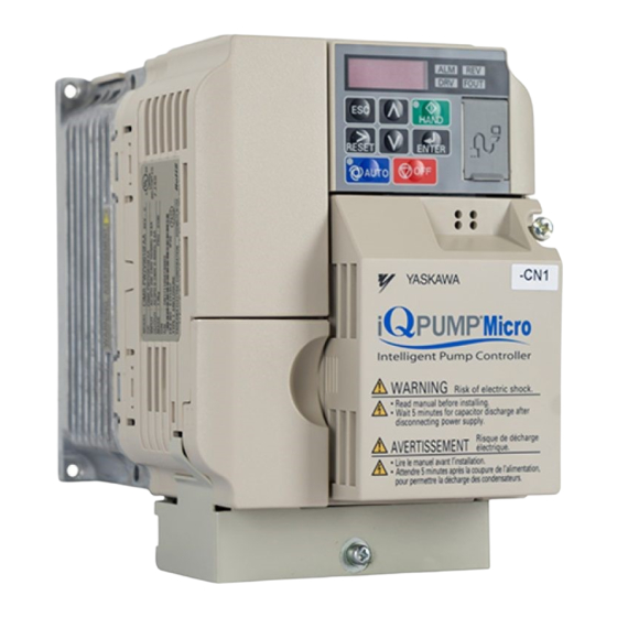
iQpump Micro AC Drive
Compact Intelligent Pump Controller
Quick Start Procedure
Type: CIMR-PW
Models: 200 V Class, Single-Phase Input: 1 to 5 HP ND
200 V Class, Three-Phase Input: 1.5 to 25 HP ND
400 V Class, Three-Phase Input: 1 to 25 HP ND
To properly use the product, read this manual thoroughly and retain
for easy reference, inspection, and maintenance. Ensure the end user
receives this manual.
MANUAL NO. TOEP YAIQPM 01A
Advertisement
Table of Contents

Related Manuals for YASKAWA iQpump Micro


Summary of Contents for YASKAWA iQpump Micro
- Page 1 Micro AC Drive Compact Intelligent Pump Controller Quick Start Procedure Type: CIMR-PW Models: 200 V Class, Single-Phase Input: 1 to 5 HP ND 200 V Class, Three-Phase Input: 1.5 to 25 HP ND 400 V Class, Three-Phase Input: 1 to 25 HP ND To properly use the product, read this manual thoroughly and retain for easy reference, inspection, and maintenance.
-
Page 2: Table Of Contents
STEP 9: FINE-TUNE SETTINGS FOR PUMPING APPLICATION ....24 STEP 10: VERIFY PUMP ROTATION AND TRANSDUCER FEEDBACK ..26 STEP 11: AUTO MODE OPERATION ..............27 STEP 12: HAND MODE OPERATION ..............28 STEP 13: YASKAWA TOEP YAIQPM 01A iQpump Micro Quick Start Procedure... -
Page 3: Step 1: Unpack The Iqpump Micro
Ensure the end user receives this manual. MANUAL NO. TOEPYAIQPM02 NOTICE: Connect LINE, MOTOR, and CONTROL circuit wiring BEFORE installing 24V power supply. LINE MOTOR 24V PS CONTROL YASKAWA TOEP YAIQPM 01A iQpump Micro Quick Start Procedure... -
Page 4: Step 2: Identify The Model For Installation
This Quick Start Procedure serves as general guide to help install, confi gure and perform test run operation. Safety Symbols in Refer to the iQpump Micro User Manual No. TOEP YAIQPM 03 for complete instructions to confi gure this this Document product for each specifi... -
Page 5: Step 3: Perform Mechanical Installation
3.1 Verify installation environment. Mechanical installation and mounting footprint vary by model. Refer to the iQpump Micro User Manual No. TOEP YAIQPM 03 , Chapter 2: Mechanical Installation for details. Ensure the installation conditions are suitable to prolong and optimize performance life. -
Page 6: Step 4: Motor, Line Power And Start/Stop Circuit
Refer to the wiring diagram below to START/STOP the drive using an external switch or contact 2-Wire Start/Stop Wiring Diagram 2-Wire Control iQpump Micro Terminals TB1-1 S5 S6 S7 HC SC H1 RP Forward Use for maintained contacts YASKAWA TOEP YAIQPM 01A iQpump Micro Quick Start Procedure... -
Page 7: Step 5: Install The 24 V Transducer Power Supply
The installed 24 V power supply option adds 27 mm (1.06 in.) to the total depth of the drive. Height and width dimensions are unaffected. 27 mm (1.06 in.) Figure 1.2 24 V Power Supply Dimensions YASKAWA TOEP YAIQPM 01A iQpump Micro Quick Start Procedure... - Page 8 Note: Screw sizes vary by 10 mm socket wrench IP66/NEMA 4X, UL 4V0018 to drive capacity. Select a Not applicable Type 4X 4V0038 screwdriver appropriate for the drive capacity. Other capacities 8 mm socket wrench YASKAWA TOEP YAIQPM 01A iQpump Micro Quick Start Procedure...
- Page 9 On IP66/NEMA 4X, UL Type 4Xenclosure models, remove the lower terminal cover (if provided) from the drive. The lower terminal cover is not present on certain models. Models With Models Without Lower Terminal Cover Lower Terminal Cover: BV0001 to BV0003 and 2V0001 to 2V0006 Lower Terminal Cover YASKAWA TOEP YAIQPM 01A iQpump Micro Quick Start Procedure...
- Page 10 The lower terminal cover is required for secure mounting of the 24V Power Supply on the models shown in Table 1.4. Contact your Yaskawa representative for ordering if you have a model listed in Table 1.4 and the lower terminal cover is not present on your drive.
- Page 11 Table 1.8. Yaskawa recommends using a long Phillips screwdriver with a magnetic tip to aid in keeping the screw captive during removal and installation. Test fit the screw (size M3.5 to M6) into each of the four ground wire drive-side ring lugs prior to installation. Ground wire selection varies by drive model.
- Page 12 Table 1.11 Connect J2 Lead Wire to Drive IP20/NEMA 1, UL Type 1 and IP66/NEMA 4X, UL Type 4X J2 Lead Wire (White) TB1-2 (A2) Terminal Ground Wire Through-slot for 24V Power Supply Wiring YASKAWA TOEP YAIQPM 01A iQpump Micro Quick Start Procedure...
- Page 13 24V Power Supply and the drive. Failure to comply may result in damage to circuitry and equipment. Table 1.14 Attach 24V Power Supply to Drive IP20/NEMA 1, UL Type 1 and IP66/NEMA 4X, UL Type 4X YASKAWA TOEP YAIQPM 01A iQpump Micro Quick Start Procedure...
- Page 14 Functional Earth Cable Shield (Earth (Blue) Ground) Output Internal Circuit Note: Refer to the iQpump Micro User Manual, (No. TOEPYAIQPM03) to program the iQpump Micro drive for network communication if required. YASKAWA TOEP YAIQPM 01A iQpump Micro Quick Start Procedure...
- Page 15 0.5 (20) AI 0.5-6WH PHOENIX CONTACT 0.75 (18) AI 0.75-6GY AI 1-6RD Note: Do not route shielded cable through bottom conduit bracket cable glands on IP20/NEMA 1, UL Type 1 enclosures. YASKAWA TOEP YAIQPM 01A iQpump Micro Quick Start Procedure...
- Page 16 Terminal Name (Function) Default Setting Tranducer Power Supply +20V to +24V Vdc 30 mA Power Supply Common 0 Vdc Analog input 4-20 mA, 0-20 mA, 0-10 Vdc Functional Earth Ground for Shielded Connection YASKAWA TOEP YAIQPM 01A iQpump Micro Quick Start Procedure...
- Page 17 IP20/NEMA 1, UL Type 1 enclosures. Table 1.19 Secure the Shielded Cable IP20/NEMA 1, UL Type 1 IP66/NEMA 4X, UL Type 4X Not applicable. Slack for Strain Relief Customer-Supplied Adhesive Mount Wire Tie YASKAWA TOEP YAIQPM 01A iQpump Micro Quick Start Procedure...
- Page 18 2V0030G to 2V0069G 5.4 to 6.0 (47.8 to 53) 4V0001G to 4V0011G 2.0 to 2.5 (17.7 to 22.1) Three-Phase 400 V Class 4V0018G to 4V0038G 5.4 to 6.0 (47.8 to 53) YASKAWA TOEP YAIQPM 01A iQpump Micro Quick Start Procedure...
-
Page 19: Step 6: Adjust And Monitor Iqpump Micro Settings
The ‘A’ 0. 8 a behind the value means ‘Amps’. Motor Current Refer to the iQpump Micro User Manual, (Document No. TOEPYAIQPM03) to access additional drive monitors YASKAWA TOEP YAIQPM 01A iQpump Micro Quick Start Procedure... -
Page 20: Step 7: Application Specific Setup
STEP Application Specifi c Setup Confi gure the iQpump Micro for a dedicated pump application. DO NOT RUN THE MOTOR. Ensure all protective covers are installed and power is turned on. Available iQpump Micro Application Macro Settings using parameter A1-03 : •... -
Page 21: Step 8: Parameter Overview-Quick Setting Menu (Simplex)
0.0 disables the function. a Delta Level from the System When P1-01, Pump Mode, is set to 3 Setpoint (MEMOBUS network), this function is active only on the fi rst drive in the network. YASKAWA TOEP YAIQPM 01A iQpump Micro Quick Start Procedure... - Page 22 Run command upon power-up. Optional step: HAND key on P5-04 HAND Key Function Enables or disables the HAND key on the 1: Enabled digital operator. Selection digital operator. 0: Disabled 1: Enabled YASKAWA TOEP YAIQPM 01A iQpump Micro Quick Start Procedure...
-
Page 23: Step 9: Iqpump Micro Parameters - Advanced Settings
P1-06, P4-12 (Thrust Bearing Frequency), or speed is 3600 RPM, minimum d2-02 (Reference Lower Limit) speed is 2400 RPM. Set minimum pump frequency to 40.0 Hz. (2400 ÷ 3600 x 60 Hz=40Hz) YASKAWA TOEP YAIQPM 01A iQpump Micro Quick Start Procedure... -
Page 24: Step 10: Fine-Tune Settings For Pumping Application
(Pump Off operation (start/stop) is from Network) when the function is active. the digital operator. The iQpump Micro waits the time specifi ed in P4-11 before auto operation becomes active when utility power is restored and P4-10 is enabled (1). - Page 25 PUMP SYSTEM FAULT SETUP The iQpump Micro can display a ‘Setpoint Not Met’ fault when the iQpump Micro is unable to maintain the programmed system setpoint due a problem with the pump system. Set P1-15 to the maximum allowed difference between setpoint and feedback level.
-
Page 26: Step 11: Verify Pump Rotation And Transducer Feedback
11.1 Check the motor for proper direction and operation. This test is performed solely from the digital operator. Apply power to the iQpump Micro after electrical connections are terminated and protective covers are installed. At this point, DO NOT RUN THE MOTOR, The digital operator should display as shown in Figure 3. -
Page 27: Step 12: Auto Mode Operation
5 80. 0 Press the AUTO button to start the iQpump Micro. The iQpump Micro starts in AUTO Mode when the feedback signal level falls below the level programmed in parameter P1-04 for the specified time in P1-05. Start Level Delay (P1-05) -
Page 28: Step 13: Hand Mode Operation
Page 28 Quick Start Procedure of 31 STEP Hand Mode Operation 13.1 HAND Mode The iQpump Micro is operated in HAND mode by performing the following tasks: • Program all parameters • Verify motor rotation direction LED Digital Operator (Standard) 0 to 10 Vdc Connection F40. - Page 29 Micro Page 29 Quick Start Procedure of 31 NOTES: YASKAWA TOEP YAIQPM 01A iQpump Micro Quick Start Procedure...
- Page 30 Micro Page 30 Quick Start Procedure of 31 NOTES: YASKAWA TOEP YAIQPM 01A iQpump Micro Quick Start Procedure...
- Page 31 Micro Page 31 Quick Start Procedure of 31 NOTES: YASKAWA TOEP YAIQPM 01A iQpump Micro Quick Start Procedure...
- Page 32 Compact Intelligent Pump Controller Quick Start Procedure YASKAWA AMERICA, INC. 2121, Norman Drive South, Waukegan, IL 60085, U.S.A. Phone: 1-800-YASKAWA (927-5292) or 1-847-887-7000 Fax: 1-847-887-7310 http://www.yaskawa.com DRIVE CENTER (INVERTER PLANT) 2-13-1, Nishimiyaichi, Yukuhashi, Fukuoka, 824-8511, Japan Phone: 81-930-25-3844 Fax: 81-930-25-4369 http://www.yaskawa.co.jp...
Need help?
Do you have a question about the iQpump Micro and is the answer not in the manual?
Questions and answers