YASKAWA Varispeed E7 Instruction Manual And Parameter Description
Hvac frequency inverter
Hide thumbs
Also See for Varispeed E7:
- Operating manual (216 pages) ,
- User manual (204 pages) ,
- Product manual (111 pages)

Related Manuals for YASKAWA Varispeed E7


Summary of Contents for YASKAWA Varispeed E7
- Page 1 (217) 352-9330 | Click HERE Find the OMRON Varispeed E7 IP54 at our website:...
- Page 2 HVAC Frequency Inverter Varispeed E7 Instruction Manual and Parameter Description Model: CIMR-E7C YEG-TOE-S616-56.1B Artisan Technology Group - Quality Instrumentation ... Guaranteed | (888) 88-SOURCE | www.artisantg.com...
- Page 3 Artisan Technology Group - Quality Instrumentation ... Guaranteed | (888) 88-SOURCE | www.artisantg.com...
-
Page 4: Table Of Contents
EMC Compatibility ..................XII Electromagnetic Compatibility (EMC) ............XIV Registered Trademarks ................XVII Handling Inverters ..............1-1 Varispeed E7 Introduction ................1-2 Varispeed E7 Applications ................1-2 Varispeed E7 Models ..................1-2 Confirmations upon Delivery ................1-4 Checks ......................1-4 Nameplate Information..................1-4 Component Names .................. - Page 5 Wire Sizes ...................... 2-19 Control Circuit Terminal Functions ..............2-21 Control Circuit Terminal Connections ............. 2-24 Control Circuit Wiring Precautions ..............2-25 Wiring Check....................2-26 Checks ......................2-26 Digital Operator and Modes............3-1 Digital Operator .................... 3-2 Digital Operator Display ................... 3-2 Digital Operator Keys ..................
- Page 6 A: Setup Settings ................... 5-10 Application Constants: b ................5-12 Tuning Constants: C..................5-18 Reference Constants: d ................. 5-21 Motor Constants: E ..................5-23 Option Constants: F ..................5-25 Terminal Function Constants: H ..............5-26 Protection Function Constants: L ..............5-32 N: Special Adjustments ..................
- Page 7 Torque Compensation for Sufficient Torque at Start and Low-speed Operation ................6-28 Hunting-Prevention Function................6-29 Machine Protection ..................6-30 Preventing Motor Stalling During Operation ........... 6-30 Detecting Motor Torque .................. 6-31 Motor Overload Protection ................6-33 Motor Overheating Protection Using PTC Thermistor Inputs ......6-35 Limiting Motor Rotation Direction and Output Phase Rotation.......
- Page 8 Using MEMOBUS Communications............... 6-68 Using the Timer Function ................6-82 Using PI Control ..................... 6-83 Energy-saving ....................6-93 Setting Motor Constants................. 6-94 Setting the V/f Pattern ..................6-95 High Slip Braking..................6-101 Digital Operator Functions ................6-102 Setting Digital Operator Functions ............... 6-102 Copying Constants ..................
- Page 9 Specifications ................9-1 Standard Inverter Specifications ..............9-2 Specifications by Model..................9-2 Common Specifications..................9-4 Appendix ................10-1 Inverter Application Precautions ..............10-2 Selection ......................10-2 Installation ...................... 10-3 Settings ......................10-3 Handling ......................10-4 Motor Application Precautions ..............10-5 Using the Inverter for an Existing Standard Motor.......... 10-5 Using the Inverter for Special Motors .............
-
Page 10: Warnings
Warnings CAUTION Cables must not be connected or disconnected, nor signal tests carried out, while the power is switched on. The Varispeed DC bus capacitor remains charged even after the power has been switched off. To avoid an electric shock hazard, disconnect the frequency inverter from the mains before carrying out maintenance. -
Page 11: Safety Precautions And Instructions For Use
Safety Precautions and Instructions for Use! 1. General Please read these safety precautions and instructions for use thoroughly before installing and operating this inverter. Also read all of the warning signs on the inverter and ensure they are never damaged or removed. Live and hot inverter components may be accessible during operation. - Page 12 This also applies to equipment with the CE mark. It is the responsibility of the manufacturer of the system or machine to ensure conformity with EMC limits. Your supplier or Yaskawa representative must be contacted when using leakage current circuit braker in con- junction with frequency inverters.
-
Page 13: Emc Compatibility
EMC Compatibility 1. Introduction This manual was compiled to help system manufacturers using YASKAWA frequency inverters design and install electrical switchgear. It also describes the measures necessary to comply with the EMC Directive. The manual's installation and wiring instructions must therefore be followed. - Page 14 – Ground the cable shields at both ends. – Ground the motor of the machine. You can find further informations in the document EZZ006543 which can be ordered at Yaskawa. XIII Artisan Technology Group - Quality Instrumentation ... Guaranteed | (888) 88-SOURCE | www.artisantg.com...
-
Page 15: Electromagnetic Compatibility (Emc)
Electromagnetic Compatibility (EMC) Recommended Line Filters for Varispeed E7 made by Schaffner EMV AG Inverter Model Line Filter (Schaffner) Current Weight Dimensions Varispeed E7 Model 55011 (kg) W x D x H Class* CIMR-E7C40P4 B, 50 m CIMR-E7C40P7 B, 50 m... - Page 16 Line Filters (Schaffner) Current Weight Dimensions Varispeed E7 Type 55011 (kg) W x D x H Class CIMR-E7C20P4 CIMR-E7C20P7 FS 5972-10-07 141 x 45 x 330 CIMR-E7C21P5 CIMR-E7C22P2 FS 5972-18-07 141 x 46 x 330 CIMR-E7C23P7 FS 5973-35-07 141 x 46 x 330...
- Page 17 Installation inverters and EMC filters Ground Bonds ( remove any paint ) Line Inverter Filter Load PE L1 Cable Length as short as possible Metal Plate Motor cable screened Ground Bonds ( remove any paint ) Artisan Technology Group - Quality Instrumentation ... Guaranteed | (888) 88-SOURCE | www.artisantg.com...
-
Page 18: Registered Trademarks
Registered Trademarks The following registered trademarks are used in this manual. DeviceNet is a registered trademark of the ODVA (Open DeviceNet Vendors Association, • Inc.). InterBus is a registered trademark of Phoenix Contact Co. • ControlNet is a registered trademark of ControlNet International, Ltd. •... - Page 19 XVIII Artisan Technology Group - Quality Instrumentation ... Guaranteed | (888) 88-SOURCE | www.artisantg.com...
-
Page 20: Handling Inverters
Handling Inverters This chapter describes the checks required upon receiving or installing an Inverter. Varispeed E7 Introduction..........1-2 Confirmations upon Delivery........1-4 Exterior and Mounting Dimensions......1-8 Checking and Controlling the Installation Site ... 1-11 Installation Orientation and Space ......1-12 Removing and Attaching the Terminal Cover ....1-13 Removing/Attaching the Digital Operator and Front Cover ............1-13... -
Page 21: Varispeed E7 Introduction
Chapter 4 Trial Operation. Varispeed E7 Models es: 200 V and 400 V. The maximum motor capacities The Varispeed E7 Series includes Inverters in two voltage class vary from 0.55 to 300 kW (42 models). Table 1.1 Varispeed E7 Models Specifications... - Page 22 Varispeed E7 Introduction Specifications Varispeed E7 Maximum (Always specify through the protective structure when ordering.) Voltage Motor Output Open Chassis Enclosed Wall-mounted Class Capacity Capacity Basic Model Number (IEC IP00) (IEC IP20, NEMA 1) CIMR-E7C CIMR-E7C 0.55 CIMR-E7C40P4 40P41 0.75...
-
Page 23: Confirmations Upon Delivery
If you find any irregularities in the above items, contact the agency from which you purchased the Inverter or your Yaskawa representative immediately. Nameplate Information There is a nameplate attached to the side of each Inverter. The nameplate shows the model number, specifica- tions, lot number, serial number, and other information on the Inverter. - Page 24 The model number of the Inverter on the nameplate indicates the specification, voltage class, and maximum motor capacity of the Inverter in alphanumeric codes. CIMR – E7 C 2 0 P4 Inverter Varispeed E7 Specification Max. Motor Capacity European Standard 0.55 kW...
-
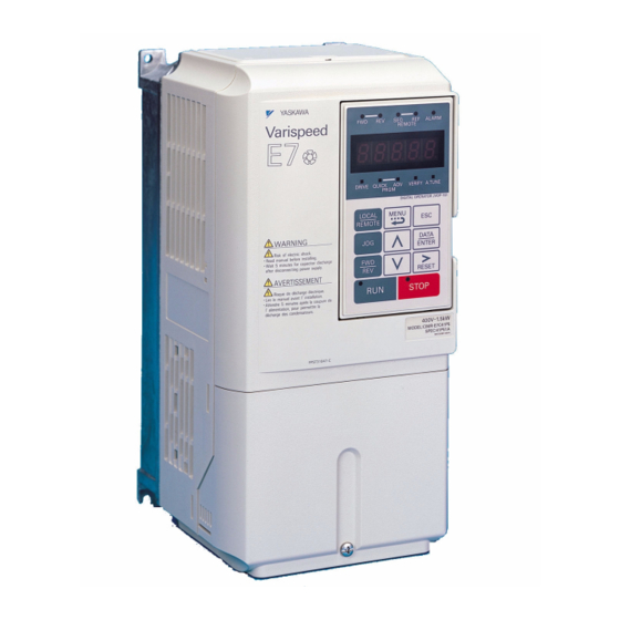
Page 25: Component Names
Component Names Inverters of 18.5 kW or Less The external appearance and component names of the Inverter are shown in 1.4. The Inverter with the ter- minal cover removed is shown in 1.5. Top protective cover (Part of Enclosed Wall- mounted Type (IEC IP20, NEMA Type 1) Mounting hole Front cover... - Page 26 Confirmations upon Delivery Inverters of 22 kW or More The external appearance and component names of the Inverter are shown in 1.6. The Inverter with the ter- minal cover removed is shown in 1.7. Mounting holes Inverter cover Cooling fan Front cover Digital Operator Nameplate...
-
Page 27: Exterior And Mounting Dimensions
Exterior and Mounting Dimensions Open Chassis Inverters (IP00) Exterior diagrams of the Open Chassis Inverters are shown below. 200 V Class Inverters of 22 or 110 kW 200 V/400 V Class Inverters of 0.55 to 18.5 kW 400 V Class Inverters of 22 to 160 kW 400 V Class Inverters of 185 to 300 kW Fig 1.8 Exterior Diagrams of Open Chassis Inverters Artisan Technology Group - Quality Instrumentation ... -
Page 28: Enclosed Wall-Mounted Inverters (Nema1)
Exterior and Mounting Dimensions Enclosed Wall-mounted Inverters (NEMA1) Exterior diagrams of the Enclosed Wall-mounted Inverters (NEMA1) are shown below. Grommet 200 V/400 V Class Inverters of 0.55 to 18.5 kW 200 V Class Inverters of 22 or 75 kW 400 V Class Inverters of 22 to 160 kW Fig 1.9 Exterior Diagrams of Enclosed Wall-mounted Inverters Artisan Technology Group - Quality Instrumentation ... - Page 29 Table 1.3 Inverter Dimensions (mm) and Masses (kg) of 200V Class Inverters and 400V Class Inverters of 0.55 to 160 kW Caloric Max. Dimensions (mm) Value(W) Appli- Cool- Voltage cable Open Chassis (IP00) Enclosed Wall-mounted (NEMA1) Total Class Motor Heat Exter Inter- Method...
-
Page 30: Checking And Controlling The Installation Site
Checking and Controlling the Installation Site Checking and Controlling the Installation Site Install the Inverter in the installation site described below and maintain optimum conditions. Installation Site Install the Inverter under the following conditions in a pollution degree 2 environment. Table 1.5 Installation Site Type Ambient Operating Temperature... -
Page 31: Installation Orientation And Space
Installation Orientation and Space Install the Inverter vertically so as not to reduce the cooling effect. When installing the Inverter, always provide the following installation space to allow normal heat dissipation. 30 mm min. 120 mm min. 30 mm min. 50 mm min. -
Page 32: Removing And Attaching The Terminal Cover
Removing and Attaching the Terminal Cover Removing and Attaching the Terminal Cover Remove the terminal cover to wire cables to the control circuit and main circuit terminals. Removing the Terminal Cover Inverters of 18.5 kW or Less Loosen the screw at the bottom of the terminal cover, press in on the sides of the terminal cover in the direc- tions of arrows 1, and then lift up on the terminal in the direction of arrow 2. -
Page 33: Removing/Attaching The Digital Operator And
Removing/Attaching the Digital Operator and Front Cover Inverters of 18.5 kW or Less To attach optional cards or change the terminal card connector, remove the Digital Operator and front cover in addition to the terminal cover. Always remove the Digital Operator from the front cover before removing the front cover. - Page 34 Removing/Attaching the Digital Operator and Front Cover Removing the Front Cover Press the left and right sides of the front cover in the directions of arrows 1 and lift the bottom of the cover in the direction of arrow 2 to remove the front cover as shown in the following illustration. Fig 1.14 Removing the Front Cover (Model CIMR-E7C45P5 Shown Above) Mounting the Front Cover After wiring the terminals, mount the front cover to the Inverter by performing the steps to remove the front...
- Page 35 1. Do not remove or attach the Digital Operator or mount or remove the front cover using methods other than those described above, otherwise the Inverter may break or malfunction due to imperfect contact. 2. Never attach the front cover to the Inverter with the Digital Operator attached to the front cover. Imperfect contact can result.
-
Page 36: Inverters Of 22 Kw Or More
Removing/Attaching the Digital Operator and Front Cover Inverters of 22 kW or More For inverters with an output of 22 kW or more, remove the terminal cover and then use the following proce- dures to remove the Digital Operator and main cover. Removing the Digital Operator Use the same procedure as for Inverters with an output of 18.5 kW or less. - Page 37 Artisan Technology Group - Quality Instrumentation ... Guaranteed | (888) 88-SOURCE | www.artisantg.com...
-
Page 38: Wiring
Wiring This chapter describes wiring terminals, main circuit terminal connections, main circuit termi- nal wiring specifications, control circuit terminals, and control circuit wiring specifications. Connections to Peripheral Devices......2-2 Connection Diagram ............2-3 Terminal Block Configuration ........2-5 Wiring Main Circuit Terminals ........2-6 Wiring Control Circuit Terminals ........ -
Page 39: Connections To Peripheral Devices
Connections to Peripheral Devices Examples of connections between the Inverter and typical peripheral devices are shown in 2.1. Power supply Molded-case circuit breaker Magnetic con- tactor (MC) AC reactor for power factor improvement Input noise filter DC reactor for power factor improvement Inverter Ground... -
Page 40: Connection Diagram
When using the Digital Operator, the motor can be operated by wiring only the main circuits. DC reactor to improve input power factor (optional) Short-circuit bar Main contactor Fuse Motor R/L1 U/T1 3-phase power supply Varispeed E7 380 to 480 V S/L2 CIMR- V/T2 Line 50/60 Hz Filter E7C47P5 T/L3 W/T3... -
Page 41: Circuit Descriptions
Circuit Descriptions Refer to the numbers indicated in 2.2. These circuits are hazardous and are separated from accessible surfaces by protective separation. These circuits are separated from all other circuits by protective separation consisting of double and rein- forced insulation. These circuits may be interconnected with SELV (or equivalent) or non-SELV circuits, but not both. -
Page 42: Terminal Block Configuration
Terminal Block Configuration Terminal Block Configuration The terminal arrangements are shown in Fig 2.3 2.4. Control circuit terminals Main circuit terminals Charge indicator Ground terminal Fig 2.3 Terminal Arrangement (200 V/400 V Class Inverter of 0.4 kW) Control Control circuit circuit terminals terminals... -
Page 43: Wiring Main Circuit Terminals
Wiring Main Circuit Terminals Applicable Wire Sizes and Closed-loop Connectors Select the appropriate wires and crimp terminals from Table 2.1 Table 2.3. Refer to instruction manual TOE-C726-2 for wire sizes for Braking Units and Braking Resistor Units. Table 2.1 200 V Class Wire Sizes Recom- Possible Inverter... - Page 44 Wiring Main Circuit Terminals Recom- Possible Inverter Tightening mended Termi- Wire Sizes Model Terminal Symbol Torque Wire Size Wire Type Screws CIMR- (N•m) (AWG) (AWG) 60 to 100 R/L1, S/L2, T/L3, 1 U/T1, 17.6 to 22.5 (2/0 to 4/0) (2/0) V/T2, W/T3, R1/L11, S1/L21, T1/L31 5.5 to 22 8.8 to 10.8...
- Page 45 Table 2.2 400 V Class Wire Sizes Recom- Possible Inverter Tightening mended Termi- Wire Sizes Wire Size Model Terminal Symbol Torque Wire Type Screws CIMR- (N•m) (AWG) (AWG) R/L1, S/L2, T/L3, 2 to 5.5 E7C40P4 1.2 to 1.5 U/T1, V/T2, W/T3 (14 to 10) (14) R/L1, S/L2, T/L3,...
- Page 46 Wiring Main Circuit Terminals Recom- Possible Inverter Tightening mended Termi- Wire Sizes Model Terminal Symbol Torque Wire Size Wire Type Screws CIMR- (N•m) (AWG) (AWG) 38 to 60 R/L1, S/L2, T/L3, 1, U/T1, V/T2, W/ 9.0 to 10.0 (2 to 1/0) T3, R1/L11, S1/L21, T1/L31 8 to 22 E7C4045...
- Page 47 Recom- Possible Inverter Tightening mended Termi- Wire Sizes Model Terminal Symbol Torque Wire Size Wire Type Screws CIMR- (N•m) (AWG) (AWG) 150 × 2P 100 to 325 R/L1, S/L2, T/L3 78.4 to 98 (300 × 2P) (4/0 to 600) 125 × 2P 100 to 325 U/T1, V/T2, W/T3, R1/L11, S1/L21, T1/L33 78.4 to 98...
-
Page 48: Main Circuit Terminal Functions
Wiring Main Circuit Terminals Terminal Screws Size Wire Thickness (mm 8 / 5 8 / 6 8 / 8 14 / 6 14 / 8 22 / 6 22 / 8 30/38 38 / 8 60 / 8 50/60 60 / 10 80 / 10 100 / 10 100 / 12... -
Page 49: Main Circuit Configurations
CIMR-E7C2037 to 2110 CIMR-E7C4075 to 4300 Control Power Power Control circuits supply supply circuits Note: Consult your Yaskawa representative before using 12-phase rectification. Artisan Technology Group - Quality Instrumentation ... Guaranteed | (888) 88-SOURCE | www.artisantg.com... -
Page 50: Standard Connection Diagrams
Wiring Main Circuit Terminals Standard Connection Diagrams Standard Inverter connection diagrams are shown in 2.5. These are the same for both 200 V Class and 400 V Class Inverters. The connections depend on the Inverter capacity. CIMR-E7C20P4 to 2018 and 40P4 to 4018 CIMR-E7C2022, 2030, and 4022 to 4055 Braking Resistor Braking Resistor... -
Page 51: Wiring The Main Circuits
Wiring the Main Circuits This section describes wiring connections for the main circuit inputs and outputs. Wiring Main Circuit Inputs Observe the following precautions for the main circuit power supply input. Installing Fuses To protect the inverter, it is recommended to use semiconductor fuses like they are shown in the table below. Table 2.6 Input Fuses Inverter Type FUSE... - Page 52 Wiring Main Circuit Terminals Installing a Moulded-case Circuit Breaker When connecting the power input terminals (R/L2, S/L2, and T/L3) to the power supply using a moulded-case circuit breaker (MCCB) observe that the circuit breaker is suitable for the Inverter. Choose an MCCB with a capacity of 1.5 to 2 times of the inverter's rated current. •...
- Page 53 Check that the motor rotates forward with the forward run command. Switch over any two of the output termi- nals to each other and reconnect if the motor rotates in reverse with the forward run command. Never Connect a Power Supply to Output Terminals Never connect a power supply to output terminals U/T1, V/T2, and W/T3.
- Page 54 Wiring Main Circuit Terminals Cable Length between Inverter and Motor If the cable between the Inverter and the motor is long, the high-frequency leakage current will increase, caus- ing the Inverter output current to increase as well. This may affect peripheral devices. To prevent this, adjust the carrier frequency (set in C6-02) as shown in Table 2.7.
- Page 55 To prevent the braking unit/braking resistor unit from overheating, design the control circuit to turn OFF the inverter output using the thermal overload relay contacts of the Unit as shown in 2.7. 200 V and 400 V Class Inverters with 0.4 to 18.5 kW Output Capacity LKEB Braking CDBR Braking...
-
Page 56: Wiring Control Circuit Terminals
Wiring Control Circuit Terminals Wiring Control Circuit Terminals Wire Sizes For remote operation using analog signals, keep the control line length between the Analog Operator or oper- ation signals and the Inverter to 50 m or less, and separate the lines from main power lines or other control cir- cuits to reduce induction from peripheral devices. - Page 57 Straight Solderless Terminals for Signal Lines Models and sizes of straight solderless terminal are shown in the following table. Table 2.10 Straight Solderless Terminal Sizes Model Manufacturer Wire Size mm (AWG) 0.25 (24) AI 0.25 - 8YE 12.5 0.5 (20) AI 0.5 - 8WH 0.75 (18) AI 0.75 - 8GY...
-
Page 58: Control Circuit Terminal Functions
Wiring Control Circuit Terminals Control Circuit Terminal Functions The functions of the control circuit terminals are shown in Table 2.11. Use the appropriate terminals for the correct purposes. Table 2.11 Control Circuit Terminals with default settings Signal Name Function Signal Level Type Forward run/stop command Forward run when ON;... - Page 59 Table 2.11 Control Circuit Terminals with default settings (Continued) Signal Name Function Signal Level Type MEMOBUS communica- Differential input, PHC tions input isolation For 2-wire RS-485, short R+ and S+ as well as R- and S-. 485/ MEMOBUS communica- Differential input, PHC tions output isolation Signal common...
- Page 60 Wiring Control Circuit Terminals Sinking/Sourcing Mode The input terminal logic can be switched between sinking mode (0-V common) and sourcing mode (+24V common) by using the terminals SN, SC, and SP. An external power supply is also supported, providing more freedom in signal input methods.
-
Page 61: Control Circuit Terminal Connections
Control Circuit Terminal Connections Connections to Inverter control circuit terminals are shown in 2.14. Varispeed E7 CIMR- E7C47P5 Forward Run/Stop Fault contact output 250 VAC, 1A max. Reverse Run/Stop 30 VDC, 1A max. External fault Fault reset Contact output 1... -
Page 62: Control Circuit Wiring Precautions
Wiring Control Circuit Terminals Control Circuit Wiring Precautions Observe the following precautions when wiring control circuits. Separate control circuit wiring from main circuit wiring (terminals R/L1, S/L2, T/L3, U/T1, V/T2, W/T3, • 2, and 3) and other high-power lines. Separate wiring for control circuit terminals MA, MB, MC, M1, M2, M3, and M4 (contact outputs) from •... -
Page 63: Wiring Check
Wiring Check Checks Check all wiring after wiring has been completed. Do not perform continuity check on control circuits. Per- form the following checks on the wiring. Is all wiring correct? • Have no wire clippings, screws, or other foreign material been left? •... -
Page 64: Digital Operator And Modes
Digital Operator and Modes This chapter describes Digital Operator displays and functions, and provides an overview of operating modes and switching between modes. Digital Operator.............3-2 Modes ................3-4 Artisan Technology Group - Quality Instrumentation ... Guaranteed | (888) 88-SOURCE | www.artisantg.com... -
Page 65: Digital Operator
Digital Operator This section describes the displays and functions of the Digital Operator. Digital Operator Display The key names and functions of the Digital Operator are described below. Drive Mode Indicators FWD: Lights up when a forward run command is input. - Page 66 Digital Operator Table 3.1 Key Functions (Continued) Name Function Enables jog operation when the Inverter is being operated from the JOG Key Digital Operator. Selects the rotation direction of the motor when the Inverter is being FWD/REV Key operated from the Digital Operator. Sets the active digit when programming user constants.
-
Page 67: Modes
Modes This section describes the Inverter's modes and switching between modes. Inverter Modes The Inverter's user constants and monitoring functions are organized in groups called modes that make it eas- ier to read and set user constants.The Inverter is equipped with 5 modes. The 5 modes and their primary functions are shown in the Table 3.2. -
Page 68: Switching Modes
Modes Switching Modes The mode selection display will appear when the MENU key is pressed from a monitor or setting display. Press the MENU key from the mode selection display to switch between the modes. Press the DATA/ENTER key from the mode selection display to monitor data and from a monitor display to access the setting display. -
Page 69: Drive Mode
Drive Mode The Drive mode is the mode in which the Inverter can be operated. The following monitor displays are possi- ble in drive mode: The frequency reference, output frequency, output current, and output voltage, as well as fault information and the fault history. When b1-01 (Reference selection) is set to 0, the frequency can be changed from the frequency setting dis- play. -
Page 70: Quick Programming Mode
Modes Quick Programming Mode In quick programming mode, the constants required for Inverter trial operation can be monitored and set. Constants can be changed from the setting displays. Use the Increment, Decrement, and Shift/RESET keys to change the frequency. The user constant will be written and the monitor display will be returned to when the DATA/ENTER key is pressed after changing the setting. -
Page 71: Advanced Programming Mode
Advanced Programming Mode In advanced programming mode all Inverter constants can be monitored and set. Constants can be changed from the setting displays. Use the Increment, Decrement, and Shift/RESET keys to change the constant. The user constant will be written and the display will return to monitor display when the DATA/ENTER key is pressed after changing the setting. - Page 72 Modes Setting User Constants Here the procedure to change C1-01 (Acceleration Time 1) from 10 s to 20 s is shown. Table 3.3 Setting User Constants in Advanced Programming Mode Step Digital Operator Display Description Power supply turned ON. MENU Key pressed to enter drive mode. MENU Key pressed to enter quick program- ming mode.
-
Page 73: Verify Mode
Verify Mode Verify mode is used to display any constants that have been changed from their default settings in a program- ming mode or by autotuning. “None” will be displayed if no settings have been changed. Even in verify mode, the same procedures can be used to change settings as they are used in the programming modes. -
Page 74: Autotuning Mode
Modes Autotuning Mode Autotuning automatically measures and sets the motor line-to-line resistance of the motor and motor cable to compensate the voltage drop and thereby to achieve the best performance. Example of Operation Set the motor rated output power (in kW) and the motor rated current, specified on the motor nameplate and then press the RUN key. - Page 75 Artisan Technology Group - Quality Instrumentation ... Guaranteed | (888) 88-SOURCE | www.artisantg.com...
-
Page 76: Trial Operation
Trial Operation This chapter describes the procedures for trial operation of the Inverter and provides an example of trial operation. Trial Operation Procedure..........4-2 Trial Operation .............4-3 Adjustment Suggestions ..........4-11 Artisan Technology Group - Quality Instrumentation ... Guaranteed | (888) 88-SOURCE | www.artisantg.com... -
Page 77: Trial Operation Procedure
Trial Operation Procedure Perform trial operation according to the following flowchart. START Installation Wiring Set power supply voltage. Turn ON power Confirm status Select operating Basic settings method. (Quick programming mode) Set E1-03. V/f default: 200V/50Hz (400V/50Hz) Motor cable over 50 m or heavy load possibly causing motor to stall or overload? -
Page 78: Trial Operation
Trial Operation Trial Operation The procedure for the trial operation is described in order in this section. Application Confirmation First, confirm the application before using the Inverter. It is designed for: Fan, blower, pump • Setting the Power Supply Voltage Jumper (400 V Class Inverters of 75 kW or Higher) The power supply voltage jumper must be set for 400 V Class Inverters of 75 kW or higher. -
Page 79: Checking The Display Status
Checking the Display Status After normal power up without any faults the operator display will show the following: The frequency reference monitor is dis- Display for normal operation played in the data display section. When a fault has occurred, the details of the fault will be displayed instead of the above display. In that case, refer to Chapter 7 Troubleshooting. -
Page 80: Basic Settings
Trial Operation Basic Settings Switch to the quick programming mode (the QUICK indicator on the Digital Operator should light) and then set the following user constants. Refer to Chapter 3 Digital Operator and Modes for Digital Operator operating procedures. Find a list of the Quick Programming Parameters on Page 5-4 and details of the parameters in... -
Page 81: Selecting The V/F Pattern
Selecting the V/f pattern Set either one of the fixed patterns (0 to D) in E1-03 (V/f Pattern Selection) or set F in E1-03 to specify a • user-set pattern as required for the motor and load characteristics in E1-04 to E1-13 in advanced program- ming mode. -
Page 82: Autotuning
Trial Operation Autotuning Autotuning for Line-to-Line Resistance Autotuning can be used to improve the performance when very long motor cables are used or when motor and inverter have different power ratings. To perform autotuning set T1-02 (Motor rated power) and T1-04 (Motor rated current) and then press the RUN key on the Digital Operator. - Page 83 Digital Operator Displays during Autotuning The following displays will appear on the Digital Operator during autotuning. Table 4.2 Digital Operator Displays during Autotuning Digital Operator Display Description Motor rated : T1-02 The autotuning start display will appear when all set- tings through T1-04 have been completed.
-
Page 84: Application Settings
Be sure to tighten all the screws when connecting the motor shaft to the mechanical system. • * Setting 3 for b1-04 will be available in future software versions. For details please contact your Yaskawa representative. Artisan Technology Group - Quality Instrumentation ... Guaranteed | (888) 88-SOURCE | www.artisantg.com... -
Page 85: Check And Recording User Constants
Operation using the Digital Operator Use the Digital Operator to start operation in LOCAL mode in the same way as in no-load operation. • For the case that a fault occurs during operation, make sure that the STOP key on the Digital Operator is •... -
Page 86: Adjustment Suggestions
L3-04 to 0. * Will be available in future software versions. For details please contact your Yaskawa representative. Artisan Technology Group - Quality Instrumentation ... Guaranteed | (888) 88-SOURCE | www.artisantg.com... - Page 87 Artisan Technology Group - Quality Instrumentation ... Guaranteed | (888) 88-SOURCE | www.artisantg.com...
-
Page 88: User Constants
User Constants This chapter describes all user constants that can be set in the Inverter. User Constant Descriptions .........5-2 Digital Operation Display Functions and Levels ..5-3 User Constant Tables ..........5-10 Artisan Technology Group - Quality Instrumentation ... Guaranteed | (888) 88-SOURCE | www.artisantg.com... -
Page 89: User Constant Descriptions
User Constant Descriptions This section describes the contents of the user constant tables. Description of User Constant Tables User constant tables are structured as shown below. Here, b1-01 (Frequency Reference Selection) is used as an example. Change MEMO- Con- Access during Setting Factory... -
Page 90: Digital Operation Display Functions And Levels
Digital Operation Display Functions and Levels Digital Operation Display Functions and Levels The following figure shows the Digital Operator display hierarchy for the Inverter. Function Page MENU Drive Mode Status Monitor Constants 5-42 Fault Trace 5-45 Inverter can be operated and Fault History 5-46 its status can be displayed. -
Page 91: User Constants Setable In Quick Programming Mode
User Constants Setable in Quick Programming Mode The minimum user constants required for Inverter operation can be monitored and set in quick programming mode. The user constants displayed in quick programming mode are listed in the following table. These, and all other user constants, are also displayed in advanced programming mode. - Page 92 Digital Operation Display Functions and Levels MEMO- Change Con- Access during Setting Factory Name Description stant Range Setting Level Regis- Opera- Number tion Sets P-control proportional gain. 0.00 Proportional b5-02 P-control is not performed when the set- 1.00 1A6H gain (P) ting is 0.00.
- Page 93 MEMO- Change Con- Access during Setting Factory Name Description stant Range Setting Level Regis- Opera- Number tion Sets the unit for b5-19, U1-38 and U1-24 0: 0.01 Hz 1: 0.01% (the maximum output frequency E1-04 is taken as 100%. 2 – 39: rpm, set value is equal to motor poles PI Setpoint Scal- 0 to...
- Page 94 Digital Operation Display Functions and Levels MEMO- Change Con- Access during Setting Factory Name Description stant Range Setting Level Regis- Opera- Number tion Sets the acceleration time to accelerate Acceleration C1-01 from 0 Hz to the maximum output fre- 200H time 1 quency.
- Page 95 MEMO- Change Con- Access during Setting Factory Name Description stant Range Setting Level Regis- Opera- Number tion 0: Stop (Operation follows the frequency reference.) Operation when 1: Operation continues at the frequency, L4-05 frequency refer- set in parameter L4-06. 0 or 1 49DH ence is missing Frequency reference loss means that the...
- Page 96 Digital Operation Display Functions and Levels MEMO- Change Con- Access during Setting Factory Name Description stant Range Setting Level Regis- Opera- Number tion Sets the brightness on the optional LCD operator (JVOP-160). 0: light o1-05 LCD-Focus 0 to 5 509H 3: normal 5: dark Selects the monitor that is displayed and...
-
Page 97: User Constant Tables
User Constant Tables A: Setup Settings Initialize Mode: A1 Change MEMO- Con- Access during Setting Factory Name Description Page stant Range Setting Level Opera- Number Register tion Used to select the language dis- played on the Digital Operator JVOP-160 only. 0: English 1: Japanese Language selec-... - Page 98 User Constant Tables Change MEMO- Con- Access during Setting Factory Name Description Page stant Range Setting Level Opera- Number Register tion Used to set a four digit number as the password. Usually this constant is not dis- 0 to A1-05 Password setting played.
-
Page 99: Application Constants: B
Application Constants: b Operation Mode Selections: b1 Change MEMO- Con- Access during Setting Factory Name Description Page stant Range Setting Level Opera- Number Register tion Sets the frequency reference input method. 0: Digital Operator Reference source b1-01 1: Control circuit terminal (analog 0 to 3 180H selection... - Page 100 User Constant Tables Change MEMO- Con- Access during Setting Factory Name Description Page stant Range Setting Level Opera- Number Register tion Sets the source of frequency refer- ence for HAND operation. HAND Fref b1-12 0: Digital Operator 0 or 1 0IE0 –...
- Page 101 Speed Search: b3 MEMO- Change Con- Access during Setting Factory Name Description Page stant Range Setting Level Regis- Opera- Number tion Enables/disables the speed search function for the RUN command and sets the speed search method. 0:Disabled, speed calculation 1: Enabled, speed calculation 2: Disabled, current detection 3: Enabled, current detection Speed Calculation:...
- Page 102 User Constant Tables Timer Function: b4 Change MEMO- Con- Access during Setting Factory Name Description Page stant Range Setting Level Opera- Number Register tion Sets the timer function output ON- delay time (dead time) for the timer Timer function 0.0 to b4-01 function input, in 1-second units.
- Page 103 Change MEMO- Con- Access during Setting Factory Name Description Page stant Range Setting Level Opera- Number Register tion 0: No detection of PI feedback loss. 1: Detection of PI feedback loss. Operation continues during Selection of PI detection, the fault contact is not b5-12 feedback signal 0 to 2...
- Page 104 User Constant Tables Change MEMO- Con- Access during Setting Factory Name Description Page stant Range Setting Level Opera- Number Register tion Sets the PI setpoint boost when the snooze mode is activated. If it is 0 to b5-25 Setpoint Boost reached once the output will be 1E7H 6-85...
- Page 105 Tuning Constants: C Acceleration/Deceleration: C1 Change MEMO- Con- Access during Setting Factory Name Description Page stant Range Setting Opera- Level Number Register tion Sets the acceleration time to accel- Acceleration C1-01 erate from 0 Hz to the 200H time 1 6-16 maximum output frequency.
- Page 106 User Constant Tables Torque Compensation: C4 Change MEMO- Con- Access during Setting Factory Name Description Page stant Range Setting Level Opera- Number Register tion Sets the torque compensation gain. Usually setting is not necessary. Adjust under the following circum- stances: •...
- Page 107 Carrier Frequency: C6 Change MEMO- Con- Access during Setting Factory Name Description stant Page Range Setting Level Opera- Number Register tion Selects the carrier frequency. Carrier frequency C6-02 Select F to enable detailed settings 0 to F 224H 4-11 selection using constants C6-03 to C6-05.
- Page 108 User Constant Tables Reference Constants: d Preset Reference: d1 Change MEMO- Con- Access during Setting Factory Name Description Page stant Range Setting Opera- Level Number Register tion Frequency refer- d1-01 Sets the frequency reference. 0.00 Hz 280H ence 1 Sets the frequency reference when Frequency refer- d1-02 multi-step speed command 1 is ON...
- Page 109 Jump Frequencies: d3 Change MEMO- Con- Access during Setting Factory Name Description Page stant Range Setting Level Opera- Number Register tion Set the center values of the jump frequencies in Hz. d3-01 Jump frequency 1 0.0 Hz 294H 6-24 This function is disabled when the jump frequency is set to 0 Hz.
-
Page 110: Motor Constants: E
User Constant Tables Motor Constants: E V/f Pattern: E1 Change MEMO- Con- Access during Setting Factory Name Description stant Page Range Setting Opera- Level Number Register tion Sets the Inverter input voltage. 155 to Input voltage set- 200 V E1-01 This setting is used as a reference value 300H 6-95... - Page 111 Motor Setup: E2 Change MEMO- Con- Access during Setting Factory Name Description Page stant Range Setting Level Opera- Number Register tion Sets the motor rated current. This set value will become the ref- 0.32 to Motor rated cur- erence value for motor protection 6-33 1.90 A E2-01...
-
Page 112: Option Constants: F
User Constant Tables Option Constants: F Communications Option Cards: F6 Change MEMO- Con- Access during Setting Factory Name Description Page stant Range Setting Opera- Level Number Register tion Set the stopping method for com- munications errors. 0: Deceleration to stop using the Operation selec- deceleration time in C1-02 F6-01... -
Page 113: Terminal Function Constants: H
Terminal Function Constants: H Multi-function Contact Inputs: H1 Change MEMO- Con- Access during Setting Factory Name Description Page stant Range Setting Opera- Level Number Register tion Terminal S3 func- Multi-function contact H1-01 0 to 6F 400H – tion selection input 1 Terminal S4 func- Multi-function contact H1-02... - Page 114 User Constant Tables Setting Function Page Value PI control disable (ON: PI control disabled) 6-86 Constants write enable (ON: All constants can be written-in. OFF: All constants are write pro- 6-109 tected.) Trim control increase (ON: d4-02 frequency is added to analog frequency reference.) 6-58 Trim control decrease (ON: d4-02 frequency is subtracted from analog frequency reference.) 6-58...
- Page 115 Setting Function Page Value agree 1 (detection width L4-02 is used.) 6-27 agree 1 (ON: Output frequency = ±L4-01, with detection width L4-02 used and during 6-27 frequency agree) Frequency detection 1 (ON: +L4-01 ≥ output frequency ≥ -L4-01, with detection width L4-02 6-27 used) Frequency detection 2 (ON: Output frequency ≥...
- Page 116 User Constant Tables Change MEMO- Access during Constant Setting Factory Name Description Page Number Range Setting Level Opera- Register tion Multi-function Selects the multi-function analog analog input ter- input function for terminal A2. H3-09 0 to 16 418H 6-22 minal A2 func- Refer to the table on the next tion selection page.
- Page 117 Multi-function Analog Outputs: H4 Change MEMO- Con- Access during Setting Factory Name Description Page stant Range Setting Level Opera- Number Register tion Sets the number of the monitor item Monitor selection H4-01 to be output (U1- ) at terminal 1 to 53 41DH 6-66 (terminal FM)
- Page 118 User Constant Tables MEMOBUS Communications: H5 Change MEMO- Con- Access during Setting Factory Name Description Page stant Range Setting Level Opera- Number Register tion 0 to 20 H5-01 Station address Sets the Inverter's node address. 425H 6-70 Sets the baud rate for MEMOBUS communications.
-
Page 119: Protection Function Constants: L
Protection Function Constants: L Motor Overload: L1 Change MEMO- Con- Access during Setting Factory Name Description Page stant Range Setting Opera- Level Number Register tion Sets whether the motor overload function is enabled or disabled at electric thermal overload relay. 0: Disabled Motor protection 1: General-purpose motor... - Page 120 User Constant Tables Power Loss Ridethrough: L2 Change MEMO- Con- Access during Setting Factory Name Description Page stant Range Setting Level Opera- Number Register tion 0: Disabled (DC bus undervoltage (UV1) detection) 1: Enabled (Restarted when the power returns within the time set in L2-02.
- Page 121 Stall Prevention: L3 Change MEMO- Con- Access during Setting Factory Name Description Page stant Range Setting Level Opera- Number Register tion 0: Disabled (Acceleration as set. With a heavy load, the motor may stall.) 1: Enabled (Acceleration stopped when L3-02 level is exceeded. Acceleration starts again when Stall prevention the current has fallen below the...
- Page 122 User Constant Tables Reference Detection: L4 Change MEMO- Con- Access during Setting Factory Name Description Page stant Range Setting Level Opera- Number Register tion Effective when "f agree 1", Speed agreement 0.0 to "Frequency detection 1" or "Fre- L4-01 0.0 Hz 499H 6-26 detection level...
- Page 123 Torque Detection: L6 Change MEMO- Con- Access during Setting Factory Name Description Page stant Range Setting Level Opera- Number Register tion 0: Overtorque/undertorque detection disabled. 1: Overtorque detection only with speed agreement; operation continues (warning is output). 2: Overtorque detected continuously during operation;...
- Page 124 User Constant Tables Hardware Protection: L8 Change MEMO- Con- Access during Setting Factory Name Description Page stant Range Setting Level Opera- Number Register tion Sets the detection temperature for the Inverter overheat detection pre- alarm in °C. Overheat pre- 50 to 95 °C* L8-02 4AEH...
-
Page 125: N: Special Adjustments
N: Special Adjustments Hunting Prevention Function: N1 Change MEMO- Con- Access during Setting Factory Name Description Page stant Range Setting Opera- Level Number Register tion 0: Hunting-prevention function Hunting-preven- disabled N1-01 tion function 0 or 1 580H 6-29 1: Hunting-prevention function selection enabled Hunting-preven-... -
Page 126: Digital Operator Constants: O
User Constant Tables Digital Operator Constants: o Monitor Select: o1 Change MEMO- Con- Access during Setting Factory Name Description Page stant Range Setting Opera- Level Number Register tion Set the number of the 3rd. monitor item to be displayed in the Drive o1-01 Monitor selection 6 to 53 500H... - Page 127 Change MEMO- Con- Access during Setting Factory Name Description Page stant Range Setting Level Opera- Number Register tion Selects the monitor that is displayed 3rd Monitor o1-08 and locked in the third line of the 1 to 53 519H – Selection operator display.
- Page 128 User Constant Tables Change MEMO- Con- Access during Setting Factory Name Description Page stant Range Setting Level Opera- Number Register tion Sets the cumulative operation time Cumulative oper- in hour units. 0 to o2-07 0 hr 50BH 6-102 ation time setting Operation time is calculated from 65535 the set values.
-
Page 129: T: Motor Autotuning
T: Motor Autotuning Change MEMO- Con- Access during Setting Factory Name Description Page stant Range Setting Level Opera- Number Register tion 0.40 Motor output Sets the output power of the motor 0.00 to T1-02 702H power in kilowatts. 650.00 0.32 to Motor rated cur- Sets the rated current of the motor 1.90 A... - Page 130 User Constant Tables Output Signal Level Dur- MEMO- Min. Constant Name Description ing Multi-Function Analog Number Unit Output Register Shows input ON/OFF status. 1: FWD command (S1) is ON 1: REV command (S2) is ON 1: Multi input 1 (S3) is ON Input terminal sta- 1: Multi input 2 U1-10...
- Page 131 Output Signal Level Dur- MEMO- Min. Constant Name Description ing Multi-Function Analog Number Unit Output Register Monitors the frequency reference after the soft starter. Output frequency This frequency value does not 10 V: Max. frequency 0.01 U1-20 after soft-starter include compensations, such as (0 to + 10 V possible) (SFS output) slip compensation.
- Page 132 User Constant Tables Fault Trace: U2 Output Signal Level MEMO- Con- Min. Name Description During Multi-Function stant Unit Number Analog Output Register U2-01 Current fault The content of the current fault. – U2-02 Last fault The error content of the last fault. –...
- Page 133 Fault History: U3 Output Signal Level Dur- MEMO- Con- Min. Name Description ing Multi-Function Analog stant Unit Number Output Register U3-01 Last fault The error content of 1st last fault. – U3-02 Second last fault The error content of 2nd last fault. –...
-
Page 134: Factory Settings That Change With The Control Method (A1-02)
User Constant Tables Factory Settings that Change with the Control Method (A1-02) 200 V and 400 V Class Inverters of 0.4 to 1.5 kW Factory Setting Constant Number Unit E1-03 E1-04 50.0 60.0 60.0 72.0 50.0 50.0 60.0 60.0 50.0 50.0 60.0 60.0... -
Page 135: Factory Settings That Change With The Inverter Capacity (O2-04)
Factory Settings that Change with the Inverter Capacity (o2-04) 200 V Class Inverters Con- stant Name Unit Factory Setting Number – Inverter Capacity 0.75 o2-04 kVA selection – Energy-saving coeffi- b8-04 – 288.20 223.70 169.40 156.80 122.90 94.75 72.69 70.44 63.13 cient Carrier frequency selec-... - Page 136 User Constant Tables 400 V Class Inverters Con- stant Name Unit Factory Setting Number – Inverter Capacity 0.75 o2-04 kVA selection – Energy-saving coeffi- b8-04 – 576.40 447.40 338.80 313.60 245.80 236.44 189.50 145.38 140.88 126.26 cient Carrier frequency selec- C6-02 –...
- Page 137 Con- stant Name Unit Factory Setting Number – Inverter Capacity o2-04 kVA selection – Energy-saving coeffi- b8-04 – 30.13 30.57 27.13 21.76 cient Carrier frequency selec- C6-02 – tion E2-01 Motor rated current 270.0 310.0 370.0 500.0 E2-03 Motor no-load current 70.0 81.0 96.0...
-
Page 138: Constant Settings By Function
Constant Settings by Function Application Selections..........6-2 Frequency Reference ..........6-5 Run Command.............6-9 Stopping Methods ............6-11 Acceleration and Deceleration Characteristics ..6-16 Adjusting Frequency References.......6-22 Speed Limit (Frequency Reference Limit Function) ..6-25 Frequency Detection..........6-26 Improved Operating Efficiency........6-28 Machine Protection ............6-30 Automatically Restart..........6-38 Inverter Protection .............6-47 Input Terminal Functions..........6-51 Output Terminal Functions......... -
Page 139: Application Selections
Application Selections Setting the Carrier Frequency Using the following constants the carrier frequency setting can be fitted to the applications requirements. Related Constants Changes Con- Setting Factory Access During Name Details stant Range Setting Level Opera- tion? Selects the carrier frequency. C6-02 Carrier frequency selection Select F to enable detailed settings using constants C6-03 to... - Page 140 Application Selections Carrier Frequency C6-03 Output frequency x C6-05 x K* C6-04 Output frequency E1-04 Max. Output Frequency Fig 6.1 *K is the coefficient determined by the set value in C6-03. C6-03 ≥ 10.0 kHz: K=3 10.0 kHz > C6-03 ≥ 5.0 kHz: K=2 5.0 kHz >...
- Page 141 Carrier Frequency and Inverter Overload Current Level The inverter overload capability depends among other things on the carrier frequency setting. If the carrier frequency setting is higher than the factory setting, the overload current capability must be reduced as shown in the tables below.
-
Page 142: Frequency Reference
Frequency Reference Frequency Reference This section explains how to input the frequency reference. Selecting the Frequency Reference Source Set constant b1-01 to select the frequency reference source. Related Constants Change Con- Setting Factory during Access stant Name Description Range Setting Opera- Level Number... - Page 143 2-Step Switching: Master/Auxiliary If 2-step switching between master and auxiliary speed frequencies is performed, input the master speed fre- quency reference to control circuit terminal A1, and input the auxiliary speed frequency reference to A2. When terminal S3 (multi-step speed command 1) is OFF, terminal A1 input (master speed frequency refer- ence) will be the Inverter frequency reference, and when terminal S3 is ON, terminal A2 input (auxiliary speed frequency reference) will be the Inverter frequency reference.
-
Page 144: Using Multi-Step Speed Operation
Frequency Reference Using Multi-Step Speed Operation With Varispeed-E7 series Inverters, you can change the speed to a maximum of 5 steps, using 4 multi-step fre- quency references, and one jog frequency reference. The following example of a multi-function input terminal function shows a 5-step operation using multi-step references 1 and 2 and jog frequency selection functions. - Page 145 Connection Example and Time Chart The following diagram shows a time chart and control circuit terminal connection example during a 9-step operation. Inverter Forward/stop Reverse/stop Error reset Multi-step command 1 Multi-step command 2 Jog frequency External fault Digital input neutral Fig 6.6 Control Circuit Terminal During 5-step Operation Frequency reference 4...
-
Page 146: Run Command
Run Command Run Command This section explains input methods for the run command. Selecting the Run Command Source Set constant b1-02 to select the source for the run command. Related Constants Change Con- Setting Factory during Access stant Name Description Range Setting Opera-... - Page 147 Performing Operations Using 3-Wire Control When any constant from H1-01 to H1-05 (multi-function contact input terminals S3 to S7) is set to 0, termi- nals S1 and S2 are used for a 3-wire control, and the multi-function input terminal that has been set to 0 works as a forward/reverse selection command terminal.
-
Page 148: Stopping Methods
Stopping Methods Stopping Methods This section explains methods of stopping the Inverter. Selecting the Stopping Method when a Stop Command is Input There are four methods of stopping the Inverter when a stop command is input: Deceleration to stop • Coast to stop •... - Page 149 Deceleration to Stop If the stop command is input (i.e., the run command is turned OFF) when b1-03 is set to 0, the motor deceler- ates to stop according to the deceleration time that has been set. (Factory setting: C1-02 (Deceleration Time If the output frequency when decelerating to stop falls below b2-01, the DC injection brake will be applied using the DC current set in b2-02 for the time set in b2-04.
- Page 150 Stopping Methods DC Braking Stop After the stop command is input and the minimum baseblock time (L2-03) has elapsed, DC injection will be applied to the motor. The applied DC injection current is programmed in parameter b2-02. The DC injection brake time depends on the set value of b2-04 and on the output frequency at the moment the stop command is input.
-
Page 151: Using The Dc Injection Brake
Using the DC Injection Brake Set constant b2-03 to apply DC injection to the motor, before it starts to accelerate. Applying DC injection at start will stop the motor before starting if it was coasting through inertia or wind mill effect. Set b2-03 to 0 to disable the DC injection brake at start. -
Page 152: Using An Emergency Stop
Stopping Methods The time chart for motor pre-heat is shown below. Motor pre-heat Output frequency b2-09 b2-09 Motor pre-heat Motor pre-heat Fig 6.15 DC Injection Brake Time Chart Using an Emergency Stop Set a multi-function input terminal (H1- ) to 15 or 17 (emergency stop) to decelerate to stop using the deceleration time set in C1-09. -
Page 153: Acceleration And Deceleration Characteristics
Acceleration and Deceleration Characteristics This section explains the acceleration and deceleration characteristics of the Inverter. Setting Acceleration and Deceleration Times Acceleration time indicates the time to increase the output frequency from 0% to 100% of the maximum out- put frequency (E1-04). Deceleration time indicates the time to decrease the output frequency from 100% to 0% of (E1-04). - Page 154 Acceleration and Deceleration Characteristics Switching Acceleration and Deceleration Time Automatically Use this setting when you want to switch acceleration/deceleration time automatically using the output fre- quency. When the output frequency reaches the set value in C1-11, the Inverter switches the acceleration/deceleration time automatically as shown in the following diagram.
-
Page 155: Preventing The Motor From Stalling During Acceleration (Stall Prevention During Acceleration Function)
Preventing the Motor from Stalling During Acceleration (Stall Prevention During Acceleration Function) The Stall Prevention During Acceleration function prevents the motor from stalling if a heavy load is applied to the motor, or sudden rapid acceleration is performed. If you set L3-01 to 1 (enabled) and the Inverter output current reaches 85 % of the set value in L3-02, the acceleration rate will begin to slow down. - Page 156 Acceleration and Deceleration Characteristics Setting Precautions If the motor capacity is small compared to the Inverter capacity or if the inverter is operated using the fac- • tory settings and the motor stalls, lower the set value of L3-02. If using the motor in the constant output range, L3-02 will be automatically lowered to prevent stalling. It •...
-
Page 157: Preventing Overvoltage During Deceleration (Stall Prevention During Deceleration Function)
Preventing Overvoltage During Deceleration (Stall Prevention During Deceleration Function) This function automatically lengthens the deceleration time with respect to the DC-bus voltage to avoid over- voltage tripping. Related Constants Change Con- Setting Factory during Access stant Name Description Range Setting Opera- Level Number... - Page 158 Acceleration and Deceleration Characteristics Setting Precautions The stall prevention level during deceleration differs depending on the inverter rated voltage and input • voltage. Refer to the following table for details. Inverter Rated/Input Voltage Stall Prevention Level during Deceleration (V) 200 V class E1-01 ≥...
-
Page 159: Adjusting Frequency References
Adjusting Frequency References This section explains methods of adjusting frequency references. Adjusting Analog Frequency References Gain and bias are among the constants used to adjust analog inputs. Related Constants Change Con- Setting Factory during Access stant Name Description Range Setting Opera- Level Number... - Page 160 Adjusting Frequency References Adjusting Frequency Bias Using an Analog Input When constant H3-09 is set to 0 (Frequency Bias), the frequency equivalent to the terminal A2 input voltage is added to A1 as a bias. Frequency bias Multi-function analog input terminal A2 input level 0V (4 mA/0 mA) Fig 6.22 Frequency Bias Adjustment (Terminal A2 Input)
-
Page 161: Operation Avoiding Resonance (Jump Frequency Function)
Operation Avoiding Resonance (Jump Frequency Function) This function allows the prohibition or “jumping” of certain frequencies within the Inverter’s output fre- • quency range so that the motor can operate without resonant oscillations caused by some machine systems. It can also be used for deadband control. •... -
Page 162: Speed Limit (Frequency Reference Limit Function)
Speed Limit (Frequency Reference Limit Function) Speed Limit (Frequency Reference Limit Function) This section explains how to limit the motor speed. Limiting Maximum Output Frequency If you do not want the motor to rotate above a given frequency, use constant d2-01. Set the upper limit value of the frequency reference as a percentage, taking E1-04 (Maximum Output Fre- quency) to be 100%. -
Page 163: Frequency Detection
Frequency Detection Speed Agreement Function There are four different types of frequency detection methods available. The digital multifunction outputs M1 to M4 can be programmed for this function and can be used to indicate a frequency detection or agreement to any external equipment. - Page 164 Frequency Detection Time Charts The following table shows the time charts for each of the speed agreement functions. L4-01: Speed Agree Level Related constant L4-02: Speed Agree Width Agree 1 Frequency reference L4-02 Output frequency or Agree motor speed L4-02 Agree 1 (Multi-function output setting = 2) Agree 1...
-
Page 165: Improved Operating Efficiency
Improved Operating Efficiency This section explains functions for improving motor operating efficiency. Torque Compensation for Sufficient Torque at Start and Low-speed Operation The torque compensation function detects a rising motor load, and increases the output torque. The inverter calculates the motor primary loss voltage and adjusts the output voltage (V) to compensate insuf- ficient torque at startup and during low-speed operation. -
Page 166: Hunting-Prevention Function
Improved Operating Efficiency Hunting-Prevention Function The hunting-prevention function suppresses hunting when the motor is operating with a light load. If high response has the priority to vibration suppression this function should be disabled (N1-01 = 0). Related Constants Change Con- Setting Factory during... -
Page 167: Machine Protection
Machine Protection Preventing Motor Stalling During Operation Stall prevention during operation prevents the motor from stalling by automatically lowering the Inverter's output frequency when a transient overload occurs while the motor is operating at a constant speed. If the Inverter output current continues to exceed the setting in constant L3-06 for 100 ms or longer, the motor speed is reduced. -
Page 168: Detecting Motor Torque
Machine Protection Detecting Motor Torque If an excessive load is applied to the machinery (overtorque) or the load suddenly drops (undertorque), you can output an alarm signal to one of the multi-function output terminal M1-M2 or M3-M4. To use the overtorque/undertorque detection function, set B or 17 (overtorque/undertorque detection NO/NC) in one of the constant H2-01 and H2-02 (multi-function output terminals M1-M2 and M3-M4 function selec- tion). - Page 169 Operator Function Overtorque/ Under- Value torque Detection 1 Overtorque detected continuously during operation; output is stopped upon OL3 lights up detection. Undertorque detection only with speed agree; operation continues (warning UL3 flashes is output). Undertorque detected continuously during operation; operation continues UL3 flashes (warning is output).
-
Page 170: Motor Overload Protection
Machine Protection Motor Overload Protection The motor can be protected from overload using the Inverter's built-in electronic thermal overload relay func- tion. Related Constants Change Con- Setting Factory during Access stant Name Description Range Setting Opera- Level Number tion Sets the motor rated current of motor 1. 0.32 to 1.90 A E2-01... - Page 171 The following diagram shows an example of the characteristics of the electronic thermal protection operation time (L1-02 = 1.0 min., operation at 50 Hz, general-purpose motor characteristics, when L1-01 is set to 1) Operating time (min.) Cold start Hot start Motor current (%) (E2-01 is set to 100%) Fig 6.24 Motor Protection Operation Time...
-
Page 172: Motor Overheating Protection Using Ptc Thermistor Inputs
Machine Protection Motor Overheating Protection Using PTC Thermistor Inputs This function provides a motor overheating protection using a thermistor (PTC characteristic – Positive Tem- perature Coefficient) that is built into the windings of each motor phase. Related Constants Change Con- Setting Factory during... - Page 173 Operation during Motor Overheating The operation when the motor overheats can be selected using the constants L1-03 and L1-04. Set the motor temperature input filter time constant in L1-05. If the motor overheats, the OH3 and OH4 error codes will be displayed on the Digital Operator.
-
Page 174: Limiting Motor Rotation Direction And Output Phase Rotation
Machine Protection Limiting Motor Rotation Direction and Output Phase Rotation If the motor reverse rotation is prohibited, a reverse run command will not be accepted, even if it is input. Use this setting for applications in which reverse motor rotation can cause problems (e.g., fans, pumps, etc.) It is also possible to change the output phase order by changing b1-04 to 2 or 3. -
Page 175: Automatically Restart
Automatically Restart This section explains functions for continuing or automatically restarting Inverter operation after a momentary power loss. Restarting Automatically After Momentary Power Loss After a momentary power loss, the Inverter can be restarted automatically to continue motor operation. To restart the Inverter after power is recovered, set L2-01 to 1 or 2. If L2-01 is set to 1, the inverter will restart, when power is recovered within the time set in L2-02. -
Page 176: Speed Search
Automatically Restart Speed Search The speed search function finds the actual speed of a motor that is coasting without control, and then starts smoothly from that speed. It is also activated after momentary power loss detection when L2-01 is set to enabled. - Page 177 Multi-function Contact Inputs Function Value External search command 1 OFF: Speed search disabled (Start from lowest output frequency) ON: Speed calculation (Calculates the motor speed, and starts search from calculated speed) Current detection (Starts speed search from maximum output frequency) External search command 2 OFF: Speed search disabled (Start from lowest output frequency) ON: Speed calculation (Calculates the motor speed, and starts search from calculated speed) (Same operation as external search...
- Page 178 Automatically Restart Speed Search Selection The speed search method can be selected using b3-01. If b3-01 is set to 0 the search method is speed calcula- tion. It has to be activated by a multi-function input (H1- set to 61 or 62). If b3-01 is set to 1, the search method is speed calculation too, but speed search is performed at every RUN command and has not to be activated by a multifunction input.
- Page 179 Speed Search after Short Baseblock (during Power Loss Recovery, etc.) Loss Time shorter than the Minimum Baseblock Time (L2-03) • AC power supply Set frequency Start using reference speed detected Output frequency Output current 10 ms *1. After AC power supply recovery, motor waits for the minimum Speed Search Wait Time (b3-05).
- Page 180 Automatically Restart Current Detection Speed Search at Startup The time chart when speed search at startup or external speed search command is selected is shown below. Deceleration time set in b3-03 Run command Set frequency Maximum output reference frequency or set frequency Output frequency b3-02...
-
Page 181: Continuing Operation At Constant Speed When Frequency Reference Is Lost
Continuing Operation at Constant Speed When Frequency Reference Is Lost The frequency reference loss detection function can be used to continue operation at reduced speed using the set value in parameter L4-06 as frequency reference value. When using an analog input as frequency reference source, a frequency reference loss is detected, when the reference value drops over 90 % in 400 ms or less. -
Page 182: Restarting Operation After Transient Error (Auto Restart Function)
Automatically Restart Restarting Operation After Transient Error (Auto Restart Function) If an Inverter error occurs during operation, the Inverter will perform self-diagnosis. If no error is detected, the Inverter will automatically restart. This is called the auto restart function. The auto restart function can be applied to the following errors. •... - Page 183 Auto Restart External Outputs To output auto restart signals externally, set H2-01 or H2-02 (multi-function contact output terminals M1-M2 or M3-M4 function selection) to 1E (auto restart). Related Constants Change Con- Setting Factory during Access stant Name Description Range Setting Opera- Level Number...
-
Page 184: Inverter Protection
Inverter Protection Inverter Protection Inverter Overheat Protection The Inverter is protected against overheating using a thermistor that detects the heatsink temperature. When the overheat temperature level is reached the inverter output is switched off. To prevent a suddenly and unexpected stop of the inverter due to an overtemperature, an overheating pre-alarm can be output. -
Page 185: Ground Fault Protection
Related Constants Change Con- Setting Factory during Access stant Name Description Range Setting Opera- Level Number tion Allowed DC bus ripple before input phase loss is detected in percent of the OV trip level. 0.0 to L8-06 Input Phase Loss Detection Level 5.0 % 200V class: 400 VDC 25.0 %... -
Page 186: Setting The Ambient Temperature
Inverter Protection Setting the Ambient Temperature The overload capability of the inverter depends on the ambient temperature. At ambient temperatures higher than 45°C (40°C for IP20/NEMA1 types) the output current capacity is reduced, i.e. the OL2 alarm level will be lowered. Related Constants Con- Change... -
Page 187: Soft Cla Selection
Soft CLA Selection Soft CLA is a current detection level for the output IGBT protection. Using constant L8-18 Soft CLA can be enabled or disabled. Related Constants Con- Change Setting Factory Access stant Name Description during Range Setting Level Number Operation 0: Disable L8-18... -
Page 188: Input Terminal Functions
Input Terminal Functions Input Terminal Functions Temporarily Switching Operation between Digital Operator and Control Circuit Terminals You can switch the Inverter run command inputs and frequency reference inputs between local (i.e., Digital Operator) and remote (input method set in b1-01 and b1-02). If any input from H1-01 to H1-05 (multi-function contact input terminal S3 to S7 function selection) has been set to 1 (local/remote selection), this input can be used to switch over between local and remote. -
Page 189: Blocking Inverter Outputs (Baseblock Commands)
Blocking Inverter Outputs (Baseblock Commands) Set 8 or 9 (Baseblock command NO/NC) in one of the constants H1-01 to H1-05 (multi-function contact input terminal S3 to S7 function selection) to perform baseblock commands using the terminal's ON/OFF operation, and thereby to block the inverter output. Clear the baseblock command to restart the operation using the speed search method set in b3-01 (speed search selection). -
Page 190: Drive Enable/Disable
Input Terminal Functions Drive Enable/Disable If a digital input is programmed for this function (H1- = 6A) the drive can be enabled or disabled by switching the digital input ON/OFF (ON – Drive enabled). If the input is switched OFF while a RUN command is active the inverter will stop using the stopping method set in b1-03. - Page 191 Time Chart The time chart when using Acceleration/Deceleration Ramp Hold commands is given below. Power supply Forward/Stop Acceleration/Deceleration Ramp Hold Frequency reference Output frequency Hold Hold Fig 6.36 Acceleration/Deceleration Ramp Hold Artisan Technology Group - Quality Instrumentation ... Guaranteed | (888) 88-SOURCE | www.artisantg.com...
-
Page 192: Raising And Lowering Frequency References Using Contact Signals (Up/Down)
Input Terminal Functions Raising and Lowering Frequency References Using Contact Signals (UP/DOWN) The UP and DOWN commands raise and lower Inverter frequency references by turning ON and OFF a multi-function contact input terminal S3 to S7. To use this function, set two of the constants H1-01 to H1-05 (multi-function contact input terminal S3 to S7 function selection) to 10 (UP command) and 11 (DOWN command). - Page 193 Application Precautions Frequency outputs using UP/DOWN commands are limited by the frequency reference upper and lower • limits set in constants d2-01 to d2-03. Here, the frequency value from analog frequency reference input A1 becomes the frequency reference lower limit. If using a combination of the frequency reference from ter- minal A1 and the frequency reference lower limit set in either constant d2-02 or d2-03, the larger limit value will become the frequency reference lower limit.
- Page 194 Input Terminal Functions Output frequency Upper limit Accelerates to lower limit Same frequency Lower limit Forward operation/stop UP command Reference frequency reset DOWN command Speed agree* Power supply * The speed agree signal turns ON when the motor is not accelerating/decel- erating while the run command is ON.
-
Page 195: Trim Control Function (+/- Speed)
Trim Control Function (+/– Speed) The +/– speed function increments or decrements the frequency reference from analog input by the value set in constant d4-02 (+/– Speed Limit) using two digital inputs. To use this function, set two of the constants H1-01 to H1-05 (multi-function contact terminal inputs S3 to S7 function selection) to 1C (Trim Control Increase command) and 1D (Trim Control Decrease command). -
Page 196: Hold Analog Frequency Using User-Set Timing
Input Terminal Functions Hold Analog Frequency Using User-set Timing When one of the constants H1-01 to H1-05 (multi-function contact input terminal S3 to S7 function selection) is set to 1E (sample/hold analog frequency command), the analog frequency reference will be held from 100 ms after the terminal is turned ON, and operation will continue at that frequency. -
Page 197: Switching Operation Source To Communication Option Card
Switching Operation Source to Communication Option Card The source of frequency reference and RUN command can be switched between a Communication option card and the sources selected in b1-01 and b1-02. Set one of the constants H1-01 to H1-05 (multi-function contact inputs S3 to S7 function selection) to 2 or 36 to enable operation source switchover. -
Page 198: Auto/Hand Mode Switching By Digital Input
Input Terminal Functions Setting for one of Terminal Frequency Reference and Run Command Source H1-01 to H1-05 Status Inverter (Frequency reference and Run command source are set in b1-01 and b1-02) MEMOBUS communication (Frequency reference and run command are input via RS-422/485) MEMOBUS communication (Frequency reference and run command are input via RS-422/485) Inverter... -
Page 199: Stopping The Inverter On External Device Errors (External Error Function)
Application Precautions Jog frequencies using FJOG and RJOG commands have the priority over other frequency references. • When both FJOG command and RJOG commands are ON for 500 ms or longer at the same time, the • Inverter stops according to the setting in b1-03 (stopping method selection). Stopping the Inverter on External Device Errors (External Error Function) The external error function activates the error contact output and stops the Inverter operation. -
Page 200: Output Terminal Functions
Output Terminal Functions Output Terminal Functions The digital multifunction outputs can be set for several functions using the H2-01 and H2-02 constants (termi- nal M1 to M4 function selection). These functions are described in the following section. Related Constants Con- Change Setting Factory... - Page 201 Zero Speed (Setting: 1) OFF The output frequency is higher than the zero speed level (b2-01). The output frequency is lower than the zero speed level (b2-01). Output frequency Zero speed level (b2-01) Zero-speed output Fig 6.41 Timing Chart for Zero-speed Inverter Operation Ready (Setting: 6) If a multifunction output is programmed for this function the output will be switched ON when the initialisa- tion of the inverter at startup has finished without any faults.
- Page 202 Output Terminal Functions Fault Reset Command Active (Setting: 11) If a multifunction output is set for this function the output is switched ON as long as a fault reset command is input at one of the digital inputs. Reverse Direction (Setting: 1A) If a multifunction output is programmed for this function the output is switched ON whenever the drive is turning the motor in the direction that corresponds to reverse direction.
-
Page 203: Monitor Constants
Monitor Constants This section explains the analog monitor and pulse monitor constants. Using the Analog Monitor Constants Related Constants Change Con- Setting Factory during Access stant Name Description Range Setting Opera- Level Number tion Sets the number of the monitor item to be output (U1- H4-01 Monitor selection (terminal FM) 1 to 38... - Page 204 Monitor Constants Adjusting the Meter The influence of the settings of gain and bias on the analog output channel is shown on three examples in 6.42. Ausgangs-Spannung/ Output voltage -Strom Gain: 170% Bias: 10V/20mA Gain: 100% Bias: 3V/8.8mA 3V/8,8mA Gain: Bias: 100% Monitor item (e.g.
-
Page 205: Individual Functions
Individual Functions Using MEMOBUS Communications You can perform serial communications with Programmable Logic Controls (PLCs) or similar devices using the MEMOBUS protocol. MEMOBUS Communications Configuration MEMOBUS communications are configured using 1 master (PLC) and a maximum of 31 slaves. Serial com- munications between master and slave are normally started by the master and the slaves respond. - Page 206 Communications Connection Terminal The MEMOBUS communications use the following terminals: S+, S-, R+, and R-. Enable the terminating resistance by turning ON pin 1 of switch S1 for the last Inverter (seen from the PLC) only. Terminating RS-422A resistance or RS-485 Switch Terminating resistance (1/2W, 110 Ohms) Fig 6.44 Communications Connection Terminal...
- Page 207 Related Constants Change Con- Setting Factory during Access stant Name Description Range Setting Opera- Level Number tion Sets the frequency reference input source 0: Digital Operator b1-01 Reference source selection 1: Control circuit terminal (analog input) 0 to 3 2: MEMOBUS communications 3: Option Card Sets the run command input source 0: Digital Operator...
- Page 208 Individual Functions Message Format In MEMOBUS communications, the master sends commands to the slave, and the slave responds. The mes- sage format is configured for both sending and receiving as shown below, and the length of data packets depends on the command (function) content. Slave address Function code Data...
- Page 209 Error Check Errors during communications are detected using CRC-16 (cyclic redundancy check, checksum method). The result of the checksum calculation is stored in a data-word (16 bit), which starting value is FFFH. The value of this word is manipulated using Exclusive OR- and SHIFT operations together with the data package that should be sent (slave address, function code, data) and the fixed value A001H.
- Page 210 Individual Functions The following example clarifies the calculation method. It shows the calculation of a CRC-16 code with the slave address 02H (0000 0010) and the function code 03H (0000 0011). The resulting CRC-16 code is D1H for the lower and 40H for the higher byte. The example calculation in this example is not done completely (normally data would follow the function code).
- Page 211 MEMOBUS Message Example An example of MEMOBUS command/response messages is given below. Reading Inverter Memory Register Contents The content of maximum 16 inverter memory registers can be readout at a time. Among other things the command message must contain the start address of the first register that is to be read out and the quantity of registers that should be read out.
- Page 212 Individual Functions Loopback Test The loopback test returns command messages directly as response messages without changing the contents to check the communications between the master and slave. You can set user-defined test code and data values. The following table shows a message example when performing a loopback test with the slave no. 1. Response Message Response Message Command Message...
- Page 213 Data Tables The data tables are shown below. The types of data are as follows: Reference data, monitor data, and broadcast data. Reference Data The reference data table is shown below. These data can be read and written. They cannot be used for monitor- ing functions.
- Page 214 Individual Functions Monitor Data The following table shows the monitor data. Monitor data can only be read. Register No. Contents Inverter status Bit 0 Operation 1: Operating 0: Stopped Bit 1 Reverse operation 1: Reverse operation 0: Forward operation Bit 2 Inverter startup complete 1: Completed 2: Not completed Bit 3 Error 1: Error...
- Page 215 Register No. Contents 0027H Output power U1-08 0028H Not used 0029H Not used 002AH Not used Control terminals input status Bit 0 Input terminal S1 1: ON 0: OFF Bit 1 Input terminal S2 1: ON 0: OFF Bit 2 Multi-function input terminal S3 1: ON 0: OFF 002BH Bit 3...
- Page 216 Individual Functions Register No. Contents 003CH Flash software number Communications error details Bit 0 CRC error Bit 1 Invalid data length Bit 2 Not used 003DH Bit 3 Parity error Bit 4 Overrun error Bit 5 Framing error Bit 6 Time-out Bits 7 to F Not used...
- Page 217 The ENTER command is enabled by writing 0 to register number 0900H or 0910H. Register No. Contents 0900H Write constant data to EEPROM, RAM is refreshed 0910H Constant data are not written to EEPROM, but refreshed in RAM only. The maximum number of times you can write to EEPROM is 100,000. Do not frequently execute ENTER commands (0900H) that write into EEPROM.
- Page 218 Individual Functions Self-Diagnosis The Inverter has a built-in function for self-diagnosing the functioning of the serial communication interface circuits. This function is called the self-diagnosis function. It uses the connected communications parts of the send and receive terminals to receive data sent by the Inverter and thereby to check if communication is per- formed normally.
-
Page 219: Using The Timer Function
Using the Timer Function The multi-function digital input terminals S3 to S7 can be used as timer function input terminals, and multi-function output terminals M1-M2 and M3-M4 can be used as timer function output terminals. By setting the delay time, you can prevent chattering of the sensors and switches. Set one of the constants H1-01 to H1-05 (multi-function contact input terminal S3 to S7) to 18 (timer func- •... -
Page 220: Using Pi Control
Individual Functions Using PI Control PI control is a method of making the feedback value (detection value) match the set target value. By combin- ing proportional control (P) and integral control (I), you can even control system with load fluctuation. The characteristics of the PI control operations are given below. - Page 221 Related Constants Change Con- Setting Factory during Access stant Name Description Range Setting Opera- Level Number tion 0: Disabled b5-01 PI control mode selection 1: Enabled 0, 1, 3 3: PI control enabled (frequency reference + PI output) 0.00 Sets P-control proportional gain. b5-02 Proportional gain (P) 1.00...
- Page 222 Individual Functions Change Con- Setting Factory during Access stant Name Description Range Setting Opera- Level Number tion Sets the operation method of the PI sleep function 0: Output frequency before Softstarter (SFS) b5-21 Sleep Function Selection 1 to 2 1: Frequency reference/PI target 2: Snooze Sets the frequency level at which the snooze operation b5-22...
- Page 223 PI Control Methods There are four PI control methods. Select the method by setting constant b5-01. Set Value Control Method PI output becomes the Inverter output frequency. PI output is added to the frequency reference as compensation value of the Inverter output frequency. PI Input Methods PI Target Value Input Methods Select the PI control target value input method according to the setting in b1-01 (Reference Selection).
- Page 224 Individual Functions PI Adjustment Examples Suppressing Overshoot If overshoot occurs, reduce Proportional gain (P), and increase integral time (I). Response Before adjustment After adjustment Time Set a Rapidly Stabilizing Control Condition To rapidly stabilize the control even if overshoot occurs, reduce integral time (I). Response Before adjustment After adjustment...
- Page 225 Suppressing Short Cycle Vibration If short cycle vibration occurs reduce the proportional gain (P), or increase the PI primary delay time constant. Response Before adjustment After adjustment Time Setting Precautions In PI control, the b5-04 constant is used to prevent the calculated integral control value from exceeding a •...
- Page 226 Frequency Reference / PI Target D1-04 Frequency Reference using multi-step Sleep function command selection b5-21 D1-02 b1-01 b5-16 on/off Delay Frequency reference D1-01 b5-01=0 Timer (U1-01) b5-15 Enable / Disable revers operation Sleep Option Card when PI output is negativ Level Sleep Function Scaling...
- Page 227 PI Feedback Loss Detection When performing PI control, be sure to use the PI feedback loss detection function. Otherwise if the PI feed- back gets lost, the Inverter output frequency may accelerate to the maximum output frequency. When b5-12 is set to 1 and the PI feedback value falls below the PI feedback loss detection level (b5-13) for a time longer than the PI feedback loss detection time (b5-14), a Fbl alarm (Feedback loss) will be displayed at the operator and inverter operation is continued.
- Page 228 Individual Functions PI Snooze Function By setting b5-21 to 2 the PI snooze function can be enabled. This software observes the output frequency (Softstarter output) and the PI feedback value to turn the inverter ON and OFF automatically as the system requires.
- Page 229 Square Root Feedback Operation If parameter b5-28 is set to 1 the feedback value is converted into a value that equals the square root of the actual feedback. This can be used to control the flow rate when a pressure sensor is used to generate a feed- back value.
-
Page 230: Energy-Saving
Individual Functions Energy-saving To perform energy saving, set b8-01 (Energy Saving Mode Selection) to 1. Related Constants Change Con- Setting Factory Access During stant Name Details Range Setting Level Opera- Number tion Select whether to enable or disable energy-saving control. b8-01 Energy-saving mode selection 0: Disable... -
Page 231: Setting Motor Constants
65.000 Note All factory-set constants are for a Yaskawa standard 4-pole motor. * 1. The setting range is 10% to 200% of the Inverter rated output current (the values shown are for a 200 V Class Inverter for 0.4 kW). -
Page 232: Setting The V/F Pattern
Individual Functions Setting the V/f Pattern Using the E1- constants the Inverter input voltage and the V/f pattern can be set as needed. It is not rec- ommended to change the settings when the motor is used in open loop vector control mode. Related Constants Change Con-... - Page 233 Characteristic Application Specifications Value 0 (F) 50 Hz specifications 60 Hz specifications These patterns are used in general applica- Constant Torque tions where the load torque is fixed, regard- 60 Hz specifications, voltage saturation at Characteristic less of rotation speed, e.g. for linear 50 Hz transport systems.
- Page 234 Individual Functions 0.4 to 1.5 kW V/f Pattern The diagrams show characteristics for a 200-V class motor. For a 400-V class motor, multiply all voltages by 2. Constant Torque Characteristics (Set Value: 0 to 3) • Set Value 0 50 Hz Set Value 1 60 Hz Set Value 2...
- Page 235 2.2 to 45 kW V/f Pattern The diagrams show characteristics for a 200-V class motor. For a 400-V class motor, multiply all voltages by 2. Constant Torque Characteristics (Set Value: 0 to 3) • Set Value 0 50 Hz Set Value 1 60 Hz Set Value 2 60 Hz...
- Page 236 Individual Functions 55 to 300 kW V/f Pattern The diagrams show characteristics for a 200-V class motor. For a 400-V class motor, multiply all voltages by 2. Constant Torque Characteristics (Set Value: 0 to 3) • Set Value 0 50 Hz Set Value 1 60 Hz Set Value 2...
- Page 237 When E1-03 is set to F (User-defined V/f pattern), you can set constants E1-04 to E1-10. If E1-03 is set to anything other than F, you can only read constants E1-04 to E1-10. If the V/f characteristics are linear, set E1-07 and E1-09 to the same value.
-
Page 238: High Slip Braking
Individual Functions High Slip Braking If the load inertia is large the high slip braking function can be used to shorten the deceleration time compared to the normal deceleration time without using a braking option, e.g. for emergency stops. The function must be activated by a multifunction input. Note: •... -
Page 239: Digital Operator Functions
Digital Operator Functions Setting Digital Operator Functions Related Constants Change Con- Setting Factory during Access stant Name Description Range Setting Opera- Level Number tion Set the number of the 3rd. monitor item to be displayed in o1-01 Monitor selection the Drive Mode. (U1- 4 to 33 (Not on LCD operator JVOP-160.) Set the monitor item to be displayed when the power sup-... - Page 240 Digital Operator Functions Change Con- Setting Factory during Access stant Name Description Range Setting Opera- Level Number tion 0: Cumulative time when the Inverter power is on. (All Cumulative operation time selec- time while the Inverter power is on is accumulated.) o2-08 0 or 1 tion...
- Page 241 Disabling the STOP Key (o2-02) This constant is used to set whether the STOP key on the operator is active during remote control (b1-02 ≠ 0) or not. If o2-02 is set to 1, a STOP command from the operators STOP key will be accepted. If o2-02 is set to 0 it will be disregarded.
-
Page 242: Copying Constants
Digital Operator Functions Energy Monitor Initialize (o2-14) This function can be used to initialize the energy monitor by setting parameter o2-14 to 1. HAND Key Funktion Selection (o2-15) With this parameter the HAND key can be disabled by setting parameter o2-15 to 0. The factory setting is 1, HAND key enabled. - Page 243 Storing Inverter set values in the Digital Operator (READ) To store Inverter set values in the Digital Operator use the following method. Table 6.2 READ Function Procedure Step Digital Operator Display Explanation Press the MENU key, and select advanced pro- gramming mode.
- Page 244 Digital Operator Functions Writing Constant Set Values Stored in the Digital Operator to the Inverter (COPY) To write constant set values stored in the Digital Operator to the Inverter, use the following method. Table 6.3 COPY Function Procedure Step Digital Operator Display Explanation Press the MENU key, and select advanced pro- gramming mode.
- Page 245 Comparing Inverter Constants and Digital Operator Constant Set Values (VERIFY) To compare Inverter constants and Digital Operator constant set values, use the following method. Table 6.4 VERIFY Function Procedure Step Digital Operator Display Explanation Press the MENU key. and select advanced pro- gramming mode.
-
Page 246: Prohibiting Writing Constants From The Digital Operator
Digital Operator Functions Prohibiting Writing Constants from the Digital Operator If you set A1-01 to 0, all constants except A1-01 and A1-04 are write protected, U1- , U2- , and will be displayed. If A1-01 is set to 1, only the constants A1-01, A1-04 and A2- can be read or written, U1- , U2-... -
Page 247: Displaying User-Set Constants Only
Displaying User-set Constants Only The A2 constants (user-set constants) and A1-01 (constant access level) can be used to establish a parameter set that contains only the most important parameters. Set the number of the constant to which you want to refer in A2-01 to A2-32, and then set A1-01 to 1. Using the advanced programming mode you can read and modify A1-01 to A1-03 and the constants set in A2-01 to A2-32 only. -
Page 248: Troubleshooting
Troubleshooting This chapter describes the fault displays and countermeasure for Inverter and motor problems. Protective and Diagnostic Functions ......7-2 Troubleshooting ............7-12 Artisan Technology Group - Quality Instrumentation ... Guaranteed | (888) 88-SOURCE | www.artisantg.com... -
Page 249: Protective And Diagnostic Functions
Protective and Diagnostic Functions This section describes the alarm functions of the Inverter. The alarm functions include fault detection, alarm detection, operation error detection, and autotuning error detection. Fault Detection When the Inverter detects a fault, the fault contact output operates, and the Inverter output is switched OFF causing the motor to coast to stop. - Page 250 Protective and Diagnostic Functions Table 7.1 Fault Displays and Processing (Continued) Display Meaning Probable Causes Corrective Actions Main Circuit Undervoltage The main circuit DC voltage is below • An open-phase error occurred at the the Undervoltage Detection Level input power supply. (L2-05).
- Page 251 Table 7.1 Fault Displays and Processing (Continued) Display Meaning Probable Causes Corrective Actions Check the size of the load and the length of the acceleration, deceler- ation, and cycle times. Motor Overheating Fault The Inverter will stop according to the The motor has overheated.
- Page 252 Protective and Diagnostic Functions Table 7.1 Fault Displays and Processing (Continued) Display Meaning Probable Causes Corrective Actions External fault (Input terminal 3) External fault (Input terminal 4) An "external fault" was input from a Remove the cause of the external External fault (Input terminal 5) multi-function input terminal (S3 to fault.
- Page 253 Table 7.1 Fault Displays and Processing (Continued) Display Meaning Probable Causes Corrective Actions Try turning the power supply off and on again. CPU internal A/D converter error The control circuit is damaged. Replace the Inverter. The Option Card is not connected Turn off the power and insert the properly.
-
Page 254: Alarm Detection
L8-02. ing) Replace the cooling fan. (Contact your The Inverter cooling fan has stopped. Yaskawa representative.) Check the size of the load and the length of the acceleration, decelera- Motor overheating tion, and cycle times. - Page 255 Table 7.2 Alarm Displays and Processing (Continued) Display Meaning Probable causes Corrective Actions External fault (Input terminal S3) (blink- ing) External fault (Input terminal S4) (blink- ing) An external fault was input from a External fault (Input terminal S5) multi-function input terminal (S3 to Remove the cause of the external fault.
-
Page 256: Operation Errors
Protective and Diagnostic Functions Operation Errors An operation error will occur if there is an invalid setting or a contradiction between two constant settings. It won't be possible to start the Inverter until the constants have been set correctly. (The alarm output and fault contact outputs will not operate.) When an operation error has occurred, refer to the following table to identify and correct the cause of the errors. -
Page 257: Errors During Autotuning
Errors During Autotuning The errors that can occur during autotuning are given in the following table. If an error is detected, the motor will coast to a stop and an error code will be displayed on the Digital Operator. The error contact output and alarm output will not function. - Page 258 Protective and Diagnostic Functions Table 7.5 Errors during Copy Function Func- Display Meaning Probable causes Corrective Actions tion Use the copy function for the same The Inverter product code or software ID does not match product code and software number number is different.
-
Page 259: Troubleshooting
Troubleshooting Due to constant setting errors, faulty wiring, and so on, the Inverter and motor may not operate as expected when the system is started up. If that occurs, use this section as a reference and perform the appropriate counter measures. If the contents of the fault are displayed, refer to Protective and Diagnostic Functions. -
Page 260: If The Motor Does Not Operate
Troubleshooting If the Motor Does Not Operate The motor does not operate when the RUN key on the Digital Operator is pressed. The following causes are possible. The operation method setting is wrong. If constant b1-02 (Operation Method Selection) is set to 1 (control circuit terminal), the motor will not operate when the RUN key is pressed. -
Page 261: If The Direction Of The Motor Rotation Is Reversed
When using a 2-wire control, set the multi-function input terminal (H1-01 through H1-05, terminals S3 to S7) to a value other than 0. The frequency reference is too low. If the frequency reference is set below the frequency set in E1-09 (Minimum Output Frequency), the Inverter will not operate. -
Page 262: If Motor Deceleration Is Slow
Troubleshooting A signal is being input to the multifunction analog input terminal A2. When “0” (frequency bias) is set for constant H3-09 (Multi-function Analog Input Terminal A2 Function Selection), a frequency corresponding to the terminal A2 input voltage (current) is added to the frequency ref- erence. -
Page 263: If Peripheral Devices Like Plc's Or Other Are Influenced By The Starting Or Running Inverter
If peripheral devices like PLC’s or other are influenced by the starting or running inverter If electrical noise is generated by Inverter perform the following countermeasures: Change the Inverter's Carrier Frequency Selection (C6-02) to lower the carrier frequency. • Install an Input Noise Filter at the Inverter's power supply input. •... -
Page 264: If The Motor Rotates Even When Inverter Output Is Stopped
Troubleshooting If the Motor Rotates Even When Inverter Output is Stopped If the motor coasts at low speed after a deceleration to stop has been executed, it means that the DC injection braking is not decelerating enough. Adjust the DC injection braking as follows: Increase the constant b2-02 (DC Injection Braking Current) setting. - Page 265 Artisan Technology Group - Quality Instrumentation ... Guaranteed | (888) 88-SOURCE | www.artisantg.com...
-
Page 266: Maintenance And Inspection
Maintenance and Inspection This chapter describes basic maintenance and inspection for the Inverter Maintenance and Inspection........8-2 Artisan Technology Group - Quality Instrumentation ... Guaranteed | (888) 88-SOURCE | www.artisantg.com... -
Page 267: Maintenance And Inspection
Maintenance and Inspection Outline of Maintenance The maintenance period of the Inverter is as follows: Maintenance Period: Within 18 months from shipping from the factory or within 12 months from being deliv- ered to the final user, whichever comes first. Daily Inspection Check the following items with the system in operation. -
Page 268: Periodic Maintenance Of Parts
Maintenance and Inspection Periodic Maintenance of Parts The Inverter consists of many parts, and these parts must be operating properly in order to ensure full func- tioning of the Inverter. Among the electronic components, there are some that require maintenance depending on their usage condi- tions. -
Page 269: Cooling Fan Replacement Outline
Cooling Fan Replacement Outline 200 V and 400 V Class Inverters of 18.5 kW or Less A cooling fan is attached to the bottom of the Inverter. If the Inverter is installed using the mounting holes on the back of the Inverter, the cooling fan can be replaced without removing the Inverter from the installation panel. - Page 270 Maintenance and Inspection 200 V and 400 V Class Inverters of 22 kW or More A cooling fan is attached to the top panel inside the Inverter. The cooling fan can be replaced without removing the Inverter from the installation panel. Removing the Cooling Fan 1.
-
Page 271: Removing And Mounting The Control Circuit Terminal Card
Removing and Mounting the Control Circuit Terminal Card Removing the Control Circuit Terminal Card 1. Remove the Digital Operator and front cover. 2. Remove the connecting line connectors connected to FE and NC on the control circuit terminal card. 3. Loosen the mounting screws (1) on the left and right sides of the control terminals until they are free. (It is not necessary to remove these screws completely. -
Page 272: Specifications
Specifications This chapter describes the basic specifications of the Inverter and specifications for options and peripheral devices. Standard Inverter Specifications ........9-2 Artisan Technology Group - Quality Instrumentation ... Guaranteed | (888) 88-SOURCE | www.artisantg.com... -
Page 273: Standard Inverter Specifications
Possible tification * 1. The maximum applicable motor output is given for a standard 4-pole Yaskawa motor. When selecting the actual motor and Inverter, be sure that the Inverter's rated current is applicable for the motor's rated current. * 2. A transformer with dual star-delta secondary is required on the power supply for 12-pulse rectification. - Page 274 Possible tification * 1. The maximum applicable motor output is given for a standard 4-pole Yaskawa standard motor. When selecting the actual motor and Inverter, be sure that the Inverter's rated current is higher than the motor's rated current. * 2. A transformer with dual star-delta secondary is required on the power supply for 12-pulse-rectification.
-
Page 275: Common Specifications
Common Specifications The following specifications apply to both 200 V and 400 V Class Inverters. Table 9.3 Common Specifications Model Number Specification CIMR-E7C Sine wave PWM Control method V/f control Speed control range 1:40 Speed control accuracy ±3 – 3% (25°C ± 10°C) Frequency control range 0.0to 120.0 Hz Digital references: ±... -
Page 276: Appendix
Appendix This chapter provides precautions for the Inverter, motor, and peripheral devices and also pro- vides lists of constants. Inverter Application Precautions ........ 10-2 Motor Application Precautions ........10-5 User Constants ............10-7 Artisan Technology Group - Quality Instrumentation ... Guaranteed | (888) 88-SOURCE | www.artisantg.com... -
Page 277: Inverter Application Precautions
Options Terminals 3 are for connecting only the options specifically provided by Yaskawa. Never connect any other devices to these terminals. Artisan Technology Group - Quality Instrumentation ... Guaranteed | (888) 88-SOURCE | www.artisantg.com... -
Page 278: Installation
Inverter Application Precautions Installation Observe the following precautions when installing an Inverter. Installation in Enclosures Either install the Inverter in a clean location where it is not subjected to oil mist, dust, and other contaminants, or install the Inverter in a completely enclosed panel. Provide cooling measures and sufficient panel space so that the temperature surrounding the Inverter does not go beyond the allowable temperature. -
Page 279: Handling
Handling Observe the following precautions when wiring or performing maintenance for an Inverter. Wiring Check The Inverter will be internally damaged if the power supply voltage is applied to output terminal U, V, or W. Check wiring for any mistakes before supplying power. Check all wiring and control sequences carefully. Magnetic Contactor Installation Do not start and stop operation frequently with a magnetic contactor installed on the power supply line. -
Page 280: Motor Application Precautions
Installation Withstand Voltage If the input voltage is high (480 V or higher) or the wiring distance is long, the motor insulation voltage must be considered. Contact your Yaskawa representative for details. Noise Noise varies with the carrier frequency. At high carrier frequencies, the noise is almost the same when the motor is operated with a commercial power supply. -
Page 281: Using The Inverter For Special Motors
Using the Inverter for Special Motors Observe the following precautions when using a special motor. Pole-changing Motor The rated input current of pole-changing motors differs from that of standard motors. Select an appropriate Inverter according to the maximum input current of the motor. Submersible Motor The rated input current of submersible motors is higher than that of standard motors. -
Page 282: User Constants
User Constants User Constants Factory settings are given in the following table. These are factory settings for a 200 V Class Inverter with 0.4 kW (open loop vector control). Table 10.1 User Constants Factory Name Setting Setting A1-00 Language selection for digital operator display (JVOP-160) A1-01 Constant access level A1-03... - Page 283 Table 10.1 User Constants Factory Name Setting Setting b5-18 PI Setpoint Selection b5-19 PI Setpoint 0.0 % b5-20 PI Setpoint Scaling b5-21 PI Sleep Function Selection b5-22 Snooze Level b5-23 Snooze Delay Time b5-24 Wake Up-level b5-25 Setpoint Boost b5-26 Maximum Boost Time b5-27 Snooze feedback...
- Page 284 User Constants Table 10.1 User Constants Factory Name Setting Setting E1-03 V/f pattern selection E1-04 Max. output frequency 50.0 Hz E1-05 Max. voltage 200.0 V E1-06 Base frequency 50.0 Hz E1-07 Mid. output frequency 2.5 Hz E1-08 Mid. output frequency voltage 15.0 V E1-09 Min.
- Page 285 Table 10.1 User Constants Factory Name Setting Setting H5-04 Stopping method after communications error H5-05 Communications error detection selection H5-06 Send wait time 5 ms H5-07 RTS control ON/OFF H5-08 Communications Selection H5-09 CE detection time 2.0 sec L1-01 Motor protection selection L1-02 Motor protection time constant 1.0 min...
- Page 286 User Constants Table 10.1 User Constants Factory Name Setting Setting N3-04 High-slip braking OL time 40 s o1-01 Monitor selection o1-02 Monitor selection after powerup o1-03 Frequency units of reference setting and monitor o1-05 LCD Focus o1-06 Monitor mode Selection o1-07 2nd monitor selection o1-08...
- Page 287 Artisan Technology Group - Quality Instrumentation ... Guaranteed | (888) 88-SOURCE | www.artisantg.com...
- Page 288 Artisan Technology Group - Quality Instrumentation ... Guaranteed | (888) 88-SOURCE | www.artisantg.com...
- Page 289 Italy, Yaskawa Electric Europe GmbH, Via Emilia Ovest 95/F 41013 Castelfranco E. (MO), Italy Tel.: +39 059 - 92 21 21, Fax.: +39 059 - 92 21 68 France, Yaskawa Electric Europe GmbH, Z.A des Béthunes, 2, rue du Rapporteur 95310 St Ouen L’Aum ne, France ô...
Need help?
Do you have a question about the Varispeed E7 and is the answer not in the manual?
Questions and answers