
Summary of Contents for CP Autosport SetupWizzard
- Page 1 OPERATING MANUAL Wheel alignment system SetupWizzard CP Tech GmbH Dornierstraße 7 D-33142 Büren Phone +49 (0) 2955 / 4849-553 E-Mail support@setupwizzard.com Internet www.setupwizzard.com Keep for future use!
- Page 2 Wheel alignment system SetupWizzard Year of manufacture: from 2015 Version 01 Edition: October 2019 © CP Tech GmbH This operating manual and all illustrations contained herein are protected by copyright. Any use outside the limitations of copyright law without our prior written approval is prohibited and liable to prosecution.
- Page 3 Camber sensor (System version Pro) ..............20 3.3.3 Toe laser ........................20 3.3.4 Leveling laser (see technical specification user manual) ......... 20 3.3.5 Transport box (flight case) ..................21 3.3.6 Platform elevations (accessories) ................21 3.3.7 Ambient conditions ....................21 Wheel alignment system SetupWizzard...
- Page 4 10 Faults and remedial measures ..................... 54 11 Service ............................55 11.1 Safety measures when carrying out service ................. 55 11.2 Inspection and service work ....................56 11.2.1 Revision SetupWizzard .................... 56 11.2.2 Accumulators ......................57 11.2.3 Batteries ........................58 CP Tech GmbH...
- Page 5 11.2.5 Service of third-party components ................58 12 Decommissioning and disposal ....................59 12.1 Decommissioning / Dismantling the machine ................ 59 13 Appendix ............................60 13.1 EC Declaration of Conformity / Declaration of incorporation ..........60 13.2 Attached documents ......................61 Wheel alignment system SetupWizzard...
- Page 6 Contents Introduction Dear customer, Thank you for deciding in favour of the SetupWizzard. This operating manual provides all the information you need to operate the Wheel alignment system SetupWizzard properly. All persons responsible for operating, maintaining, cleaning, and troubleshooting the measuring system must read, understand and heed the operating manual.
-
Page 7: Notational Conventions
Contents Notational conventions Passages of this operating manual that require special attention or are a direct hazard warning are shown as follows: 1.1.1 Section-related warnings Section-related warnings are not limited to just one specific action but apply to all the actions performed within a section. - Page 8 This symbol warns of hand injuries when setting up the measuring system. Warning of laser beams This symbol warns of laser beams (leveling laser, toe laser, positioning laser). Warning of obstacles on the ground This symbol warns of obstacles on the ground (cables, tools, ...). Wheel alignment system SetupWizzard...
-
Page 9: Warranty And Liability
Contents Warranty and liability The obligations under the supply contract, the general delivery terms and conditions of the measuring system and the legal regulations in force at the time the contract was signed will apply. All information in this operating manual has been compiled in line with the applicable standards and regulations, the state of the art, and our longstanding knowledge and experience. -
Page 10: Guarantee Terms
33142 Büren / Germany Phone: +49 (0) 2955 / 4849-553 support@setupwizzard.com www.setupwizzard.com In addition, our employees are consistently interested in new information and experiences resulting from the application that may be of value in improving our products. Wheel alignment system SetupWizzard... -
Page 11: Intended Use
Contents Safety Failure to observe the safety information below may have serious consequences: – Risk to persons due to electrical, mechanical or chemical effects – Failure of important functions – Environmental damage due to leaking hazardous substances Read the safety and hazard information in this section thoroughly before putting the measuring system into operation. -
Page 12: Foreseeable Misuse
Electrical specialists have been trained for their specific point of deployment and know the relevant standards and regulations. Wheel alignment system SetupWizzard... -
Page 13: Obligations Of Personnel
Contents 2.2.1 Responsibilities Inappropriate handling can lead to severe personal injury and material damage. All activities must therefore be carried out by qualified personnel only. – Personnel must consist of individuals who can be expected to perform their work reliably. Individuals whose response is impaired by drugs, alcohol, medication, and the like must not work on the measuring system. -
Page 14: General Safety Information
CP Tech GmbH. Always keep the operating manual at the measuring system’s point of deployment. It – must be ensured that all personnel working on the measuring system can view the operating manual at any time. Wheel alignment system SetupWizzard... - Page 15 Contents Safety measures for environment protection In all work obey the regulations for waste avoidance and proper waste disposal/recycling. In the course of installation, maintenance and decommissioning, in particular, it must be ensured that materials which could jeopardize the groundwater – such as greases, oils, coolants, solvent-containing cleaning fluids and the like –...
- Page 16 Equipment is portable if, by its nature and in its normal use, it is moved while under power. This includes, for example, electric floor cleaners. – Alterations at electrical equipment made after testing must comply with DIN EN 60204-1. Wheel alignment system SetupWizzard...
- Page 17 CP Tech GmbH Dornierstraße 7 33142 Büren / Germany Phone: +49 (0) 2955 / 4849-553 support@setupwizzard.com www.setupwizzard.com In addition, our employees are consistently interested in new information and experiences resulting from the application that may be of value in improving our products.
-
Page 18: Personal Protective Equipment
Before switching the measuring system on, always make sure that all safety devices and guards have been fitted properly and are functional. – When subcomponents are delivered, the plant operator must ensure that the guards are fitted according to the rules. Wheel alignment system SetupWizzard... - Page 19 Contents Information for emergencies Preventive measures – Always be prepared for accidents or fires. – Keep first aid equipment (first aid box, blankets etc.) and fire extinguishers at hand. – Familiarize the personnel with accident reporting, first aid, fire-extinguishing, and rescue equipment.
- Page 20 The plant operator must regularly check that all safety devices are functioning correctly and are complete. – The plant operator must regularly check that all safety and warning signs on the measuring system are legible and stay on the measuring system. Wheel alignment system SetupWizzard...
-
Page 21: Scope Of Supply
Contents Description of the measuring system Scope of supply 3.1.1 Scope of supply of the system version Easy 1 Setup wheel, incl. wheel adapter (4x) 4 Positioning template, loose (2x) 2 Rim scale for toe measurement (4x) 5 Positioning template, fixed (2x) 3 Setup platform (4x) CP Tech GmbH... - Page 22 1 Setup wheel, incl. wheel adapter (4x) 5 Setup platform (4x) 2 Height measuring module (4x) 6 Track gauge (1x) 3 Leveling laser, incl. stand (1x) 7 Positioning template, loose (2x) 4 Toe measuring module (4x) 8 Positioning template, fixed (2x) Wheel alignment system SetupWizzard...
- Page 23 Contents 3.1.3 Scope of supply of the system version Pro 1 Transport box, incl. charger (1x) 7 Measuring platform (4x) 2 Camber measuring sensor 8 Track gauge (1x) (inclinometer) (4x) 9 Positioning template, loose (2x) 3 Setup wheel, incl. wheel adapter (4x) 10 Leveling laser, incl.
-
Page 24: Rating Plate
The rating plate including CE marking with the following minimum information should be affixed to the flight case (multilingual, if necessary). • SetupWizzard • Serial no. • Year of manufacture Optional: • Voltage/frequency • Connected load • Weight • CE mark Wheel alignment system SetupWizzard... -
Page 25: Technical Data
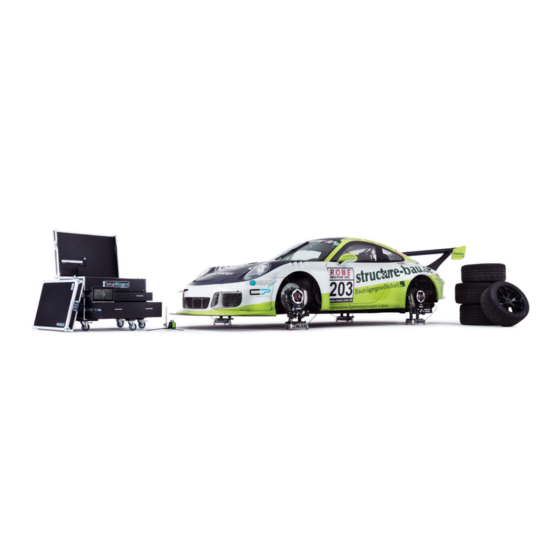
Contents Function The wheel alignment system SetupWizzard in the Easy, Basic and Pro version is only intended for the measurement of vehicle suspension. It is predominantly used in motor racing. Special setup wheels with vehicle-specific wheel adapters are installed at the vehicle. The vehicle is thus lowered onto four measuring platforms aligned by laser leveling and then secured with positioning templates against unintentional movement. -
Page 26: Ambient Conditions
85mm Adjustment range platform elevations + platform 130mm 3.3.7 Ambient conditions Permissible ambient temperature during operation +10° C to +40° C Permissible ambient temperature in storage +5° C to +40° C Permissible humidity 80% relative humidity Wheel alignment system SetupWizzard... - Page 27 Contents Transport and storage (by manufacturer) The measuring system is transported by a transport company authorized by CP Tech GmbH. The following transport containers are used: – System version Easy: Cardboard box – System version Basic: Cardboard box – System version Pro: Flight case NOTE In order to ensure that the measuring system will function safely and precisely, the transport regulations of CP Tech GmbH must be strictly...
-
Page 28: Safety During Transport
Wear protective clothing, safety shoes, and safety gloves when working. – Make sure that nobody is in the transport route. – Only lift the measuring system/component at the intended points. – Always lift the measuring system slowly and carefully. Wheel alignment system SetupWizzard... -
Page 29: Intermediate Storage
Contents Intermediate storage If the measuring system is not used directly after delivery, it must be stored carefully in a protected location. The measuring system must be temporarily stored, ensuring it is protected against cold, moisture, soiling, and mechanical influences. For the recommended storage conditions of the measuring system, please refer to „3.3.3 Ambient conditions”. - Page 30 (tire and vehicle data). If no customer data are available, the delivery will be made in dismantled condition. NOTE Fine adjustment to tire types to achieve the specified precision must be carried out by the plant operator. Wheel alignment system SetupWizzard...
- Page 31 Contents Installation by plant operator WARNING Injury hazard when lifting and installing the components! – Take hold of the measuring system components only at the intended points. Wear personal protective equipment. WARNING Trip hazard due to objects on the floor (tools, cables, compressed air hoses) –...
- Page 32 Ball caster Tire radius [mm] Wheel offset [mm] 300-315 315-330 330-345 345-360 10-50 37.5-77.5 To further increase the accuracy of the measuring system, it makes sense to set the setup wheels exactly to the tires used. Wheel alignment system SetupWizzard...
- Page 33 Contents The desired tire radius is adjusted by means of various shims (1mm, 2mm, 4mm and 8mm) and different stand positions. The universal stand can also be rotated to achieve a larger adjustment range. In this case, the shims are installed between the universal stand and the ball roller.
- Page 34 The first position of the ball caster covers the adjustment range of 10-50mm. Ball caster position A The second position of the ball caster covers the adjustment range of 37.5-77.5mm. Ball caster position B Wheel alignment system SetupWizzard...
- Page 35 Contents Replacing the wheel adapters If different vehicles are to be measured, the wheel adapters may have to be replaced. It should be noted that the wheel adapter can also be rotated after the conversion and sits backlash-free in the setup wheel. To change the wheel adapter, first remove the setup wheel from the vehicle.
-
Page 36: Setting Up The Software
SetupWizzard icon. For a better order of the computer, we recommend copying the folder of the SetupWizzard software into the program folder and creating a desktop shortcut. - Page 37 The user interface of the software is basically divided into six sections: 1. Buttons for controlling the program functions Configuration, Adjustment, and Help. 2. Management of several SetupWizzard systems, Start and Stop button for switching data transmission on/off, and an individually writable text field.
- Page 38 Device status Switched off LED off Device starting LED lights up for 1s Switched on 1x flashing, 1s repeat time Connected to software 2x flashing, 1s repeat time Pair radio connection 3x flashing, 1s repeat time Wheel alignment system SetupWizzard...
- Page 39 Contents You can charge the accumulators of the platform and connect the optional CAN charger via the charging/communication jack. The accumulator compartment accommodates the two „eneloop AA” accumulators, which you can remove, charge or replace if necessary. Always ensure that the accumulators are inserted correctly.
- Page 40 This is done in the configuration menu of the SetupWizzard software. To do this, open the SetupWizzard software and select the menu item „Config” → „Systems”. Now assign the respective vehicle corners to the measuring platforms. The designation of the platform can be found on the underside sticker.
- Page 41 Contents 7.3.4 Taring the wheel load scales Use the buttons on the left of the user interface to tare the wheel load scales. You can use the „Zero Adjust“ tare function to shift the zero point of the wheel load scales determined by calibrating the load cell. To do this, click the „Set“...
-
Page 42: Floor Requirements
A loss of stability of the setup platforms may result in a significant risk of injury. – The floor must be straight and level. – floor must have necessary load capacity. The plant operator is responsible for the structural stability of the floor. Wheel alignment system SetupWizzard... - Page 43 Contents Setting up the measuring system 8.2.1 Installing the setup wheels First, position your vehicle at the intended measuring location. Lift the vehicle as intended and exchange the vehicle wheels with the setup wheels of the measuring system. NOTE Observe the labeling and assignment of the setup wheels. Tighten the setup wheels to the torque of the vehicle wheels.
- Page 44 WARNING Injury hazard due to laser beams Laser beams can cause eye injury. • Do not stare directly into the laser beam. Wheel alignment system SetupWizzard...
- Page 45 Contents Now insert the leveling sleeves into the holes provided in the load plate. Check the set height at all three corners and adjust if necessary. To do this, loosen the clamping screws at the corner of the measuring platform with the supplied 4 mm hexagon socket wrench.
- Page 46 For the measurement, extend the track gauge to the appropriate length for the vehicle and secure the set length with the clamps. Once set, the length between the measurements on the front and the rear axle may no longer be adjusted, as this would falsify the result. Wheel alignment system SetupWizzard...
- Page 47 Contents 1 Ball lock pin 3 Clamping screw 2 Scale value on laser shaft 4 Scale value on track gauge Attach the gauge to the measuring slide and the reference end to the left and the right setup wheel of the axle using the ball lock pins. Then read the measured value at the measuring slide and adjust it on both sides of the measured axle at the laser.
- Page 48 8.2.6 Functional testing of the toe lasers Before delivery, our SetupWizzard components undergo intensive quality inspections and functional tests. This enables and ensures accurate measurement of the vehicle. However, to guarantee correct functioning of the toe laser after improper use or transport, you can carry out the following inspections.
- Page 49 (inclinometer) camber sensor rotated 180° Now start the SetupWizzard software to continue with the adjustment of the inclinometer. After connecting the platforms to the netbook, the display value of the inclinometer should first be adjusted to the real conditions; if the display value is sufficiently accurate, further adjustment is not necessary.
- Page 50 The new inclination of the sensor is stored internally and finally the mean value of the two values is calculated and the zero point adjusted. Successful calibration is confirmed. Repeat this procedure for the three remaining inclinometers. Wheel alignment system SetupWizzard...
-
Page 51: Safety Measures During Normal Operation
Inspect the measuring system for externally visible damage. Measuring the suspension 9.2.1 Measuring the wheel loads The SetupWizzard software is required to measure wheel loads. Start it as described above and establish the connection between the netbook and the measuring platforms. The current measured value... - Page 52 The toe measuring modules are equipped with a millimeter scale as standard. When reading the values, it is important to read in the middle range of the laser beam. If the beam is too far up or down, there may be slight deviations. Wheel alignment system SetupWizzard...
- Page 53 Due to the stronger deflection of the measured value in the SetupWizzard, the measuring system can deliver correspondingly more accurate results. This considerably improves the reproduction of measurement results.
- Page 54 If the setup wheels are set correctly, you can measure the ride height of the vehicle directly above the road surface. Wheel alignment system SetupWizzard...
- Page 55 Contents Operating the accessory components The accessory components can significantly increase the range of functions of the Pro system version and expand its area of application. 9.3.1 Caster measurement With optional caster measurement, you have the possibility to measure the caster as well as the SAI of your suspension geometry.
- Page 56 The measuring accuracy is +/- 0.3°; the repeatability is +/- 0.2°. NOTE Important: The other side of the vehicle cannot be measured with the mirror on one side, because the steering trapezoid produces different steering angles for left and right. Wheel alignment system SetupWizzard...
- Page 57 Contents 9.3.2 Platform elevations The platform elevations extend the Pro version with a multitude of options. The one hand, the adjustment range of the platforms increases significantly, so that larger terrain unevenness can be compensated. On the other hand, the platform elevations (only when additional chassis stands are used) also allow work to be carried out under the vehicle.
- Page 58 USB connection. Use the „Start CAN” button to establish the connection to the platforms. The status LEDs in the cover of the charger now indicate whether all measuring platforms are connected via CAN and whether the communication is working. Wheel alignment system SetupWizzard...
-
Page 59: Faults And Remedial Measures
Contents Faults and remedial measures Device Problem Solution proposal Cannot be switched on Replace depleted accumulators with charged ones or connect power supply unit Overload display Remove weight from platforms No display Platform switched on and connected to PC Connection to PC not Platform switched on and activate connection via available radio or CAN... - Page 60 Make sure that all tools, materials and other equipment have been removed from the work area. – Clean up the work area. Remove any leaked liquids and similar substances. Make sure that all the measuring system’s safety devices are functioning correctly. – Wheel alignment system SetupWizzard...
- Page 61 Inspection and service work 11.2.1 Revision SetupWizzard The SetupWizzard system consists exclusively of high-quality components and is maintenance free. CP Tech GmbH prescribes an annual revision of the system in order to guarantee the quality and accuracy of the system and its operation.
- Page 62 If the accumulators in the measuring platforms are damaged or become defective in between inspection intervals, they may only be replaced with identical „Panasonic eneloop AA 2000mAh” accumulators. NOTE Replacing the accumulators with batteries can lead to defects in the measuring platforms and is therefore prohibited. Wheel alignment system SetupWizzard...
-
Page 63: Electrical Equipment
Contents 11.2.3 Batteries The batteries in the toe or leveling laser may have replaced between maintenance intervals, depending on how long the system has been in use. For the toe laser, you must remove the four screws of the cover plate on the underside and remove the plate. -
Page 64: Decommissioning And Disposal
– Dispose of the measuring system in an environment-friendly manner, separating the various materials. – Dispose of lubricants and lube oils in conformity with valid regulations or, if necessary, contact CP Tech GmbH. Wheel alignment system SetupWizzard... - Page 65 D-33142 Büren hereby declare that the wheel alignment measuring system SetupWizzard by CP autosport, version: 2.0, in the system versions Easy, Basic and Pro complies with the basic safety requirements of the Low Voltage Directive 2014/35/EU, as well as the EMC Directive 2014/30/EU.
-
Page 66: Attached Documents
Contents 13.2 Attached documents The following documents are provided with this operating manual: – Drawings: - Assy Platform - Assy Height Extension - Assy Setup Wheel Wheel alignment system SetupWizzard...
Need help?
Do you have a question about the SetupWizzard and is the answer not in the manual?
Questions and answers