Nuova Simonelli Talento Service Manual
Hide thumbs
Also See for Talento:
- User handbook manual (38 pages) ,
- User manual (100 pages) ,
- User handbook manual (192 pages)
Table of Contents
Advertisement
Advertisement
Chapters
Table of Contents

Related Manuals for Nuova Simonelli Talento


Summary of Contents for Nuova Simonelli Talento
- Page 1 SERVICE MANUAL...
- Page 2 Edition Date Changes on last versions 12/2013 Inserimento specifiche Talento Special...
-
Page 3: Table Of Contents
CALIBRATION ..... . 2.14 SECONDARY BOARD 2.3.1 RIGHT GRINDER ADJUSTMENT 2.14 (TALENTO SPECIAL ONLY)... . 6.6 2.3.2 LEFT GRINDER ADJUSTMENT .2.14 TRANSFORMER FOR 2.3.3... - Page 4 14.6 POURING NOZZLE WASH 11.4.3 STEAM TEMP TALENTO PLUS ....14.7 (STEAM BOILER 14.7 POURING NOZZLE WASH TEMPERATURE) ... 11.11 TALENTO SPECIAL .
- Page 5 SPARE PART CATALOGUE ..17.1 17.1 TALENTO ......17.2 17.2 FRIDGE .
- Page 6 SERVICE MANUAL Edition 02 to 12/2013...
-
Page 7: Index
Handling ....1.8 types of venue. At the push of a button, Talento grinds, presses and pours excellent espressos, cappuccinos and many of the other coffee-based beverages in demand the world over. -
Page 8: Description
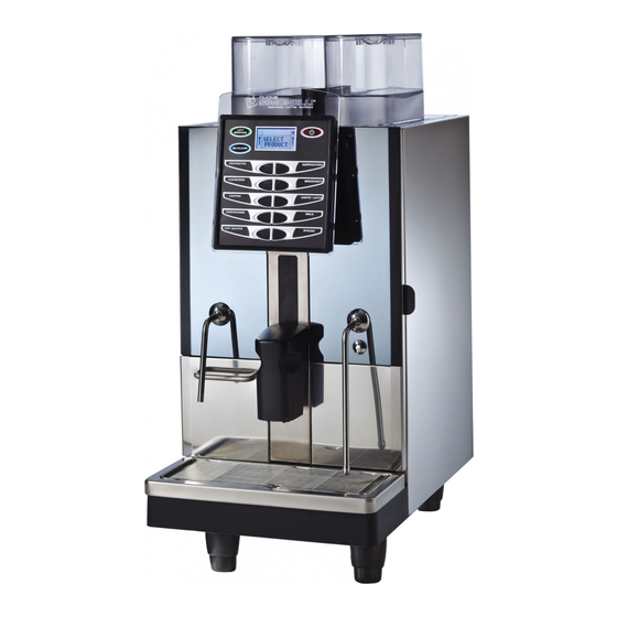
SERVICE MANUAL DESCRIPTION Fig. 2 KEY: Coffee bean holder cap Control panel Front door Steam pipe / Hot water pipe Drop collecting tray grid Coffee grounds drawer Coffee nozzles Milk/Cappuccino nozzle Control panel hatch opening / locking key 10 Ground coffee conveyor hat ch 11 Milk suction tube 12 Milk flow adjusting tap 13 Water collecting tray... -
Page 9: Keyboard Description
SERVICE MANUAL KEYBOARD DESCRIPTION (Standard configuration) Fig. 3 KEY: Left grinder key On/Off key Programming key Product dose keys Double dose/cleaning cycle key Edition 02 to 12/2013... -
Page 10: Safety Instruction
SERVICE MANUAL SAFETY INSTRUCTION Fig. 5 This book is an integral and essen- tial part of the product and must be given to the user. Read this book care- fully. It provides important information concerning safety of installation, use and maintenance. Save it carefully for future reference. - Page 11 SERVICE MANUAL This appliance must only be used as described in this handbook. The manu- foot; facturer shall not be liable for any dam- age caused due to improper, incorrect shower rooms; and unreasonable use. socket to disconnect it from the mains; At the end of installation, the device is Fig.
- Page 12 SERVICE MANUAL If the appliance breaks down or fails to Fig. 10 work properly, switch it off. Any inter- vention is strictly forbidden. Contact qualified experts only. Repairs should only be made by the manufacturer or authorized service centres. Only origi- nal spare parts must be used.
- Page 13 SERVICE MANUAL CAUTION CAUTION RISK OF CUTTING When adding coffee beans, the machine INFORMATION TO THE USERS operator must not place his/her hands Under the senses of art. 13 of Law inside the container. Decree 25th July 2005, n. 151 “Implementation of the Directives/ Guidelines 2002/95/CE, 2002/96/CE and 2003/108/CE, concerning the...
-
Page 14: Transport And Handling
SERVICE MANUAL TRANSPORT AND CAUTION HANDLING RISK OF IMPACT OR CRASHING Before carrying out the following operation, 1.4.1 MACHINE the load must be checked to ensure that it IDENTIFICATION is in the correct position and that, when the supports are cut, it will not fall. Always quote the machine serial number in all The operator, who must first put on work communications to the manufacturer, Nuova... -
Page 15: First-Time Installation And
LEFT GRINDER ADJUSTMENT .2.14 2.3.3 MILK TEMPERATURE (Talento Plus only)... 2.15 2.3.4 MILK FOAM ....2.15 2.3.5... - Page 16 SERVICE MANUAL RISK OF POLLUTION Do not dispose of packaging in the environ- ment. Fig. 2 Before carrying out any installation and adjustment operations you must read and fully understand the SAFETY INSTRUCTIONS of this handbook. The company cannot be held responsible for damage to things or injury to persons caused by failure to comply with the safety instructions and installation...
-
Page 17: First-Time Installation
In this section the technical data of Talento are listed and first installation is safety guided. 2.1.1 WEIGHT AND DIMENSIONS Talento is 840 mm high, 400 mm wide and 600 mm deep. It’s net weight is 65 kilos. NET WEIGHT 65 Kg 143.3 lb... -
Page 18: Water Supply And Drainage
Fig. 7 power input, 3000W, but it takes more time to heat up. When using the parallel option, Talento needs 5600W power to heat up but, it then needs a minimum time to get back up to temperature, especially when making long beverages. - Page 19 SERVICE MANUAL The machine has a ready-connected 3/4 water Fig. 10 supply pipe. During initial installation, the service engineer needs to: Fit a filter to the end of the pipe and connect this to the water mains (Fig. 9). Make sure that the inlet pressure is <4 bar and if this is not the case, fit a suitable pres- sure reducer.
-
Page 20: Optional Direct Grounds Discharge
SERVICE MANUAL 2.1.4 OPTIONAL DIRECT GROUNDS Fig. 14 DISCHARGE All machines are equipped with direct hole for coffee grounds discharge. Optional is the drawer with a funnel going to a conveyor that expels the grounds directly into the rubbish. Fit the con- veyor funnel into the drawer. -
Page 21: Lubrication
SERVICE MANUAL WARNING WHEN INSTALLING FOR THE FIRST TIME OR STARTING THE MACHINE AGAIN AFTER BOILER TANK GROUP SERVICING, BEFORE SWITCHING ON THE MACHINE AND STARTING THE HEATING PROCESS, BE SURE TO FILL THE COFFEE BOILER TANK, UNTIL THERE IS A REGULAR FLOW FROM THE COFFEE NOZZLE (See par 12.2 at page 12.3). -
Page 22: Filling The Coffee Bean Container
SERVICE MANUAL 2.1.7 FILLING THE COFFEE BEAN Fig. 19 CONTAINER Use ONLY toasted coffee beans into the cof- fee bean holder. Don’t insert caramelized, sugar coated or similar coated coffee beans, instant coffee or any other sugary beverages because they will harm the appliance. Listed below some possible configurations for containers: Right: espresso beans for single and double... -
Page 23: Milk Fridge (Optional)
SERVICE MANUAL 2.1.9 MILK FRIDGE (Optional) Fig. 23 Connect the milk fridge to the machine using the support in the milk fridge box. Temperature suggested to set by the display +5°C. A big milk container, 3-4liters, is recommended to obtain a better stability in Temperature, volume and foam quality of the milk products. -
Page 24: Change Products Name
Fig. 28 To change the products names labels remove the plastic cover and slide out the label from side. BASIC PROGRAMMING Fig. 29 Preliminary informations to start Talento’s pro- gramming. 2.2.1 LANGUAGE PROGRAMMING With the machine switched off, hold down the ON/OFF key (approx. -
Page 25: Beverages Programming
1,5; TAMPING yes. TALENTO SPECIAL ONLY: TEMPERATURE 7, DELAY 0 if the fridge is on the left side; move up if the fridge is on the right side or under the counter. Cycle MILK COFFEE if you want white top in the cup or COFFEE MILK if... - Page 26 SPEED: available only in Talento Special for COLD MILK: from 50 to 100%, control the speed of the motor pump. NOTE: In Talento Special set a minimum of 2 sec on the parameter “NO AIR TIME” for all the milk beverages. This expedient removes drops of condensation in the piping system, result- ing in a constant production on milk foam beverages.
-
Page 27: Setting Programming
SERVICE MANUAL 2.2.3 SETTING PROGRAMMING After PROG DOSES press down to reach SETTING. It is the temperature of the water in the coffee boiler used to brew coffee, sug- gested value between 88 to 98; the temperature change the color and the taste in the espresso, 90-92 for lighter color cream, less bitterness more acidity (more COFFEE then 40% robusta percentage in the blend);... -
Page 28: Calibration
SERVICE MANUAL CALIBRATION An overview of adjustments and settings to tune Talento machines. 2.3.1 RIGHT GRINDER ADJUSTMENT Fig. 30 Use a flathead screwdriver. Turn clockwise to increase fineness and anticlockwise to reduce it. When adjusting, make maximum 1 turn and... -
Page 29: Milk Temperature (Talento Plus Only)
SERVICE MANUAL 2.3.3 MILK TEMPERATURE Fig. 32 (Talento Plus only) Use the white screw to adjust temperature. Starting point: close completely the screw and then unscrew for 2 turn and half. Turn clockwise to reduce flow and therefore, increase tem- perature;... -
Page 30: Easycream
SERVICE MANUAL 2.3.5 EASYCREAM Fig. 36 Use a flathead screwdriver on the top right side of the machine to adjust the air and therefore, the foam in the milk. Turn anticlockwise to increase foam and clockwise to reduce it. We recommend performing this operation while actually pouring steam in the milk. -
Page 31: Pouring Group
SERVICE MANUAL POURING GROUP Fig. 1 INDEX POURING GROUP ....3.1 ACCESS ......3.3 POURING GROUP REMOVAL . - Page 32 SERVICE MANUAL TOOLS REQUIRED: Fig. 2 Pliers teflon 10 mm socket wrench Clamps 3 mm allen key Scotch 2,5 mm allen key 10 mm wrenches 2 mm allen key 17 mm wrenches Small phillips screwdriver 17 mm wrenches Small phillips screwdriver 21 mm wrenches Pin extractor Edition 02 to 12/2013...
-
Page 33: Access
SERVICE MANUAL ACCESS To access the pouring group, just open the Fig. 3 door. The service engineer needing to intervene on the system will need to: Switch off the machine. Remove the ground drawer. Turn the key anticlockwise. Open the front panel. The pouring group is in the middle. - Page 34 SERVICE MANUAL Remove the group wiring plug. Fig. 6 Remove the pouring pipe pressing the Fig. 7 metal ring and pulling the teflon pipe. Fig. 8 Loosen the top screw from the pouring Fig. 9 group using a 7 mm socket wrench. Remove the botton screw, holding the group in place with one hand.
-
Page 35: Group Motor Removal
SERVICE MANUAL GROUP MOTOR REMOVAL Fig. 10 The service engineer now needs to: Remove the two screws at the top, under the upper motor bracket with the 10 mm wrench. Slide out the motor. Remove the faston connections. This operation can be carried out with the group fitted to the machine and following the same procedure. - Page 36 SERVICE MANUAL The temperature probe (A) is located at the base of the infusion chamber. To remove it: Use a 2,5 mm allen wrench to remove the Fig. 13 screw. Free the wiring from the clamps and Fig. 14 disconnect the two pins from the wiring connector.
-
Page 37: Movement Screw And Bearings Removal
SERVICE MANUAL MOVEMENT SCREW AND Fig. 15 BEARINGS REMOVAL To remove the movement screw it is neces- sary to: Remove the group from the machine (see par. 3.2). Take out the motor (see par. 3.3). Remove the four 2.5 mm allen screws from the top support of the group. - Page 38 SERVICE MANUAL Correctly position the first worm screw Fig. 19 bearing which is comprised of two wash- ers with a grooved part inside and the balls in the centre. Insert the bushing inside the support. Fig. 20 Insert the support into the worm screw. Fit the second bearing.
-
Page 39: Infusion Chamber And Micromagnetic Removal
SERVICE MANUAL INFUSION CHAMBER AND MICROMAGNETIC REMOVAL To remove the infusion chamber, it is neces- sary to: Remove the group from the machine (see Fig. 22 par. 3.2). Remove the motor from the group (see par. 3.3). Loosen the two 10 mm screws in the bottom group support and the two rear phillips screw. - Page 40 SERVICE MANUAL On the back of the group chamber is placed Fig. 25 the magnet which closes the microswitch sensors for the group position. The back plate of the pouring group contains Fig. 26 the three microswitches for group position- ing: Top position B Middle position...
-
Page 41: Blade Ejector Worm Screw And Blade Ejector Removal
SERVICE MANUAL BLADE EJECTOR WORM Fig. 28 SCREW AND BLADE EJECTOR REMOVAL The blade ejector worm screw is located on the lower support bracket of the group. To rimove it: Remove the pouring group (see par. 3.2). Fig. 29 Take out the worm screw by removing the two screws on the base with a phil- lips screwdriver. -
Page 42: Upper Piston Gasket
SERVICE MANUAL UPPER PISTON GASKET Fig. 32 AND SHOWER Remove the ground drawer (A), turn the key anticlockwise (B) and open the frost door (C). Take out the top piston by removing the Fig. 33 motor cover with a phillips screwdriver and loosening a nut (See par 3.2). -
Page 43: Lower Piston Gasket And Shower - Spare Parts Replacement
SERVICE MANUAL Using a flat head screwdriver, remove the Fig. 36 seal and rinse off the seating and also the piston surface or soak them in hot water and pulicaff. Use a screwdriver to insert the new seal and make sure that it fits perfectly in the seating. - Page 44 SERVICE MANUAL Press key number 6 to move the cham- Fig. 40 ber in top position. Slide out the springs (C) and remove the central o-ring (D) on the bottom piston shaft. Press the number 7 key and release it Fig.
-
Page 45: Reassembling
SERVICE MANUAL Fig. 44 Using a flathead screwdriver, take out Fig. 45 the screw securing the shower to the pis- ton, clean the shower with a damp cloth or soak it in a solution of hot water and Pulicaff for a few minutes (10 min). If the shower is too dirty, replace it with a new one. - Page 46 SERVICE MANUAL Insert the support and spring. Fig. 48 Fit the o-ring in the middle of the bottom Fig. 49 piston shaft together with the previously assembled springs. Press the key number 7 to lower the Fig. 50 chamber and release it when the piston is about to enter the bottom support of the spring.
-
Page 47: Microswitch Position
SERVICE MANUAL Press 8 to move to an intermediate posi- Fig. 52 tion and refiit the temperature probe. Press the keys 6, 7 and 8 in sequence to move the group and make sure that the top and the bottom positions are cor- rectly aligned. -
Page 48: Guides Cleaning
Use a teflon spray to lubricate the movement Fig. 58 screw near the plastic nut. Use a Nuova Simonelli silicon grease to lubri- Fig. 59 cate the movement screw bearings. 3.18 Edition 02 to 12/2013... -
Page 49: Boiler Tanks
SERVICE MANUAL BOILER TANKS Fig. 1 INDEX BOILER TANKS ....4.1 ACCESS ......4.3 BOILER TANKS AND FUSE COMPONENTS . - Page 50 SERVICE MANUAL TOOLS REQUIRED: Fig. 2 Pliers Clippers 37 mm wrench 17 mm wrench 12 mm wrench 10 mm wrench Phillips screwdriver Clamps Edition 02 to 12/2013...
-
Page 51: Access
SERVICE MANUAL ACCESS Fig. 3 To access the boiler tank assembly, the engi- neer needs to: Undo the two back screws on the top panel with a phillips screwdriver. Remove the back panel. Coffee boiler tank is on the left and it has a capacity of 2 litres;... - Page 52 D Water inlet connection Hot water solenoid valve (version with hot water economizer) connection To replace the fuse placed in the bottom part Fig. 10 of the boiler tank, it’s necessary to: Switch off the machine. Unplug the Talento. Edition 02 to 12/2013...
-
Page 53: Draining The Boilers
SERVICE MANUAL Disconnect the fuse connections and Fig. 11 slide out the fuse from the bottom. DRAINING THE BOILERS Fig. 12 The boiler tank needs to be emptied in order to change the heating element or before removing the boiler assembly. To empty the coffee boiler tank, the engineer needs to: Switch off the machine. -
Page 54: Heating Element
SERVICE MANUAL Insert a drain pipe. Fig. 15 Open a fitting in the top part of the boiler Fig. 16 to allow air to enter and therefore, water comes out. Wait for the tank to empty completely and then tighten the fitting that was previously opened using a 12 mm wrench before clos- ing the plug again. - Page 55 SERVICE MANUAL Unhook the power cord for the heating Fig. 19 element (steam or coffee). Unhook the teflon water inlet pipes in the bottom part of the boiler. Open the right side panel, loosening the Fig. 20 two screws on the top panel with a phil- lips screwdriver.
- Page 56 SERVICE MANUAL Fig. 23 WARNING Use a vise to unhook the heating element. Move the boiler tank to the edge of the vise and secure it at the lower surface level (weld joint), to avoid cylinder damage. 11 Securing the boiler in a vise and using a 37 mm wrench it is possible to loosen and unscrew the heating element dur- ing the refitting stages, make sure that...
-
Page 57: Solenoid Valves, Flowmeter And Check Valves
SERVICE MANUAL SOLENOID VALVES, FLOWMETER AND CHECK VALVES Fig. 1 INDEX SOLENOID VALVES, FLOWMETER AND CHECK VALVES... . . 5.1 ACCESS ......5.3 FLOWMETER AND CHECK VALVE. - Page 58 SERVICE MANUAL TOOLS REQUIRED: Fig. 2 Clamps Clippers 14 mm wrenches 12 mm wrenches 7 mm wrenches Phillips screwdriver Pipes in teflon Edition 02 to 12/2013...
-
Page 59: Access
SERVICE MANUAL ACCESS Fig. 3 For access to the solenoid valve assembly, the engineer needs to: Make sure that the machine is switched off. Using a phillips screwdriver, loosen the two screws on the top panel. Remove the left side panel. FLOWMETER AND CHECK VALVE Fig. -
Page 60: Coffee Solenoid Valve
SERVICE MANUAL Lower down, from the left are: Fig. 7 Hot water economizer with regulation Add water bypass Automatic level solenoid Fig. 8 COFFEE SOLENOID VALVE To remove the coffee solenoid valve, the engi- neer needs to: Switch off the machine. Remove the grounds drawer. - Page 61 SERVICE MANUAL Remove the pouring tube, pressing on the Fig. 11 ring and pulling the teflon tube outwards. Fig. 12 Remove the silicon pipe for drain. Unscrew the two phillipe screw near the fit- ting. To remove the coffee solenoid valve definitely: Fig.
-
Page 62: Heating Element For Coffee Valve
SERVICE MANUAL HEATING ELEMENT FOR Fig. 15 COFFEE VALVE Use the same procedure to remove and change the heating element for coffee valve. Loose the 2 mm allen screw (A) and slide out the heating element. The connection is inside the machine opening the rear panel. -
Page 63: Electrical Parts
(TALENTO SPECIAL ONLY)... . 6.6 TRANSFORMER FOR EASYCREAM (TALENTO PLUS ONLY)....6.8 Edition 02 to 12/2013... - Page 64 SERVICE MANUAL TOOLS REQUIRED: Fig. 2 Pliers 5 mm allen key Phillips crosshead screwdriver Phillips head screwdriver Edition 02 to 12/2013...
-
Page 65: Access
SERVICE MANUAL ACCESS Fig. 3 To access to the electrical parts, the engineer needs to: Switched off the machine. Use a phillips head screwdriver to loosen the two screws (A) in the top of the right side panel and remove it. Fig. - Page 66 SERVICE MANUAL Remove the sleeve from the clock battery Fig. 7 (present only when cpu board is replaced by a new one); M Check the position of the red wire in the flat cable connected to the pcb. It must be on bottom.
- Page 67 SERVICE MANUAL Fig. 10 Edition 02 to 12/2013...
-
Page 68: Transformer
SECONDARY BOARD (TALENTO SPECIAL ONLY) Fig. 14 The secondary board is only in Talento Special; it controls the low voltage of milk pump and air compressor motors.. To take out the secondary board, disconnect all the wirings and the four screws securing the unit to the frame. - Page 69 SERVICE MANUAL Fig. 15 Edition 02 to 12/2013...
-
Page 70: Transformer For Easycream (Talento Plus Only)
TRANSFORMER FOR Fig. 16 EASYCREAM (TALENTO PLUS ONLY) When the Talento Plus is equipped with Easycream (optional) above the main board is the transformer to control the compressor that push air into the Easycream system. The transformer is connected to the board and it is in parallel with the air solenoid valve for Easycream. -
Page 71: Pump And
SERVICE MANUAL PUMP AND WATER STOP SOLENOID Fig. 1 INDEX PUMP AND WATER STOP SOLENOID ..7.1 ACCESS ......7.3 PUMP AND PRESSURE GAUGE ADJUSTMENT . - Page 72 SERVICE MANUAL TOOLS REQUIRED: Fig. 2 Long phillips head screwdriver 7 mm wrench 12 mm wrench Clippers Clamps Short phillips head screwdriver Flathead screwdriver Edition 02 to 12/2013...
-
Page 73: Access
SERVICE MANUAL ACCESS Fig. 3 The engineer needs to: Switched off the machine. Remove the grounds drawer. Turn the key anticlockwise. Open the front panel. PUMP AND PRESSURE Fig. 4 GAUGE ADJUSTMENT To adjust pump pressure, the engineer needs to: Switched off the machine. -
Page 74: Pump Replacement
SERVICE MANUAL PUMP REPLACEMENT Fig. 7 To replace the pump the engineer needs to: Switched off the machine. Remove the grounds drawer. Turn the key anticlockwise. Open the front panel. Remove the water try. Fig. 8 Fig. 9 Remove the four screws supporting the bot- tom front panel. - Page 75 SERVICE MANUAL Open the water inlet fitting by loosening the Fig. 11 screw with a 12 mm wrench. Remove the outlets using the 12 mm wrench on both unions. 10 Remove the clamp connecting the pump to Fig. 12 the motor using a phillips head screwdriver. 11 Take out the pump.
-
Page 76: Motor Replacement
SERVICE MANUAL MOTOR REPLACEMENT Fig. 14 After separating the pump from the motor (sec- tion 7.3), the engineer needs to: Lift up the machine (5 centimeter at least) placing four suitable supports under the feet. Remove the two nuts under the machine, using a 7 mm wrench. -
Page 77: Waterstop Replacement
SERVICE MANUAL WATERSTOP REPLACEMENT Fig. 17 To replace the waterstop the engineer needs to: Switch off the machine. Remove the grounds drawer. Turn the key anticlockwise. Open the front panel. Remove the water tray. Fig. 18 Remove the four screws supporting the bot- Fig. - Page 78 Take out the two connection fastons. Fig. 22 10 Shut off the incoming water and disconnect the Talento water inlet pipe. 11 Remove the two screws under the coffee machine using a short phillips screwdriver. 12 Cut the clamp securing the drain pipe to the Fig.
-
Page 79: Grinders
SERVICE MANUAL GRINDERS Fig. 1 INDEX GRINDERS..... . 8.1 CONTAINER AND MICRO ... . 8.3 GRINDER ACCESS AND CHANGING . - Page 80 SERVICE MANUAL TOOLS REQUIRED: Fig. 2 Phillips screwdriver 13 mm wrench Flathead screwdriver 3 mm allen key Edition 02 to 12/2013...
-
Page 81: Container And Micro
SERVICE MANUAL CONTAINER AND MICRO Fig. 3 The engineer needs to: Switched off the machine. Remove the grounds drawer. Turn the key anticlockwise. Open the front panel. To remove the coffee containers, the engineer Fig. 4 needs to: Close the two gates that close the contain- ers to prevent leaking of coffee beans. -
Page 82: Grinder Access And Changing
SERVICE MANUAL GRINDER ACCESS AND Fig. 7 CHANGING After removing the containers: Remove the four phillips head screw in the top panel. Disconnect the wiring. Fig. 8 The two microswitches for the containers and the Fig. 9 micros for decaffeinated coffee chute are located in the back part of the top panel. - Page 83 SERVICE MANUAL To change the grinder blades, the engineer Fig. 11 needs to: If not done yet, close the two tabs and remove the containers. Empty the grinders by residual coffee beans: if possible use a vacuum machine, otherwise grind the remaining beans: and down arrow keys for 8 seconds: the display will read “TEST”.
-
Page 84: Ventilation System
SERVICE MANUAL Fig. 15 Screw on the top grinder completely until it touches and than turn it quarter a turn back. Secure it to grinder and reassemble the whole unit. Fig. 16 fineness to obtain the desired coffee quality. Fig. 17 VENTILATION SYSTEM The service engineer will needs to: Switched off the machine. -
Page 85: Grinder Chute
SERVICE MANUAL As well as the grinders, in the top part of the Fig. 19 machine it’s possible to see the conveyors of the two types of ground coffee, the fan for the ground coffee chute (A) (0,08 A) and the fan to cool the containers (B) (0,15 A), which serves to keep coffee bean quality at a constant level. -
Page 86: Changing The Condenser
SERVICE MANUAL CHANGING Fig. 23 THE CONDENSER To access the condenser, the service engineer will have to: Switched off the machine. Remove the rear panel by taking out the two screws with a phillips head screwdriver (A). remove the right side panel too. To remove the capacitors: Fig. - Page 87 VALVE FOR HOT MILK ..9.9 AIR REGULATOR FOR COLD MILK (TALENTO SPECIAL ONLY)... 9.10 ADJUSTING KNOB....9.11 PIPES CONNECTIONS .
- Page 88 SERVICE MANUAL TOOLS REQUIRED: Fig. 2 Phillips screwdriver Phillips flathead screwdriver Edition 02 to 12/2013...
-
Page 89: Milk Circuit Talento Plus
SERVICE MANUAL MILK CIRCUIT TALENTO Fig. 3 PLUS 9.1.1 CAPPUCCINO MAKER AND NOZZLE To access the cappuccino maker, the engineer will need to: Switch off the machine. Unhook the plastic cover of the pouring nozzle moving up the metal lock. - Page 90 SERVICE MANUAL 9.1.2 WASHING AND Fig. 7 AIR SOLENOIDS To access to the washing and air solenoids, the engineer needs to: Switch off the machine. Remove the grounds drawer. Turn the key anticlockwise. Open the front panel. The guides for the milk and coffee pouring pipes Fig.
- Page 91 SERVICE MANUAL Returning to the front of the machine: Fig. 11 Take out the milk solenoid valve block. 6a Disconnect the inlet tube for washing water. Fig. 12 6b Disconnect the milk tube. Fig. 13 The milk solenoid valve block is composite of: Fig.
- Page 92 SERVICE MANUAL MILK CIRCUIT TALENTO SPECIAL The new milk system produce an higher density cream. Furthermore it’s possible to prepare dif- ferent temperature beverages and also to obtain the “cold milk foam”, a cold milk cream beverage for the milk products lovers.
- Page 93 SERVICE MANUAL The cappuccino maker is composed on: Fig. 18 Steam and milk mixer Filter Milk conveyer Fig. 19 To remove the milk pump 24V, Loose the two fillips screws. Remove the metal support with the milk pump. Remove the white pipe. Disconnect the power cables.
- Page 94 SERVICE MANUAL 9.2.2 NOZZLE Fig. 21 To access the pouring nozzle, the engineer will need to: Switch off the machine. Unhook the plastic cover of the pouring noz- zle moving up the metal lock. Fig. 22 The pouring nozzle contains: Milk diffuser Pipe for coffee (Blue) Pipe to add hot water (Teflon)
-
Page 95: Washing And Air Solenoids
SERVICE MANUAL The air compressor 24V is in the right side, Fig. 25 it injects air in the steam line coming to the cappuccino maker. The T fitting is only in the machine equipped by the EASYCREAM wand. Fig. 26 The solenoid valve and the regulator for cold milk are in the top left side. -
Page 96: Air Regulator For Cold Milk
Operation should be performed while foamed milk is being poured, i.e. press cappuccino bot- ton.). AIR REGULATOR FOR COLD MILK (TALENTO SPECIAL ONLY) Fig. 31 With a flathead screwdriver at the top left side (rear part) of the machine, adjust the air and therefore, the milk foam: Turn anticlockwise to increase the foam. -
Page 97: Adjusting Knob
SERVICE MANUAL ADJUSTING KNOB Fig. 32 After found the final settings for hot milk foam it’s possbile to fix the plastic knob available in the box. The knob has a pin to reduce the setting range available for the end customer ½ turn, Put the pin in the centre of the slot. -
Page 98: Pipes Connections
SERVICE MANUAL PIPES CONNECTIONS Fig. 34 PIPING SV SERVICE TALENTO PLUS with EASYCREAM Compressor L=25 blue Air regulator Easycream L=48 red Sv steam wand L=14 red L=81.5 red Wand [Lenghts are in cm] 9.12 Edition 02 to 12/2013... - Page 99 SERVICE MANUAL Fig. 35 PIPING SV SERVICE TALENTO SPECIAL without EASYCREAM Cold milk air regulator Compressor L=44 white SV air+cleaning L=75 blue L=41.5 red L=8 red L=4 white SV steam cappuccino maker L=5 white L=73 white L=19 red Milk pump...
- Page 100 SERVICE MANUAL Fig. 36 PIPING SV SERVICE TALENTO SPECIAL with EASYCREAM Cold milk air regulator Compressor L=44 white L=5 blue SV air+cleaning L=70 blue L=20 blue L=8 red Air milk regulator L=4 white L=41.5 red SV cappuccino maker L=5 white...
- Page 101 SERVICE MANUAL DOOR Fig. 1 INDEX DOOR ......10.1 10.1 INTRODUCTION ....10.3 10.2 DISPLAY AND BUTTON PAD .
- Page 102 SERVICE MANUAL TOOLS REQUIRED: Fig. 2 2 - 5 mm allen key Phillips head screwdriver 7 mm wrench 10.2 Edition 02 to 12/2013...
-
Page 103: Introduction
SERVICE MANUAL 10.1 INTRODUCTION Fig. 3 On the outside of the door starting from the bot- tom we can see: The hot water wand The pouring nozzle The steam wand The housing for an optional autosteam noz- zle probe In the top part we have: Fig. -
Page 104: Pouring Nozzle, Tunnel
SERVICE MANUAL Using a phillips screwdriver, it’s possible to Fig. 7 remove the display board: Take out the four screws. Take out the flat wire connecting to the main circuit board. 10.3 POURING NOZZLE, TUNNEL Fig. 8 AND GUIDES The pouring nozzle is located in the front of the machine. -
Page 105: Grounds Drawer And Micro
SERVICE MANUAL 10.4 GROUNDS DRAWER AND Fig. 10 MICRO Open the door and remove the ground drawer; There is a magnet (A) inside the drawer that closes a micro (B) inside the machine. The micro signals the presence of the grounds drawer. -
Page 106: Glass Replacement
SERVICE MANUAL To remove the hot water wand, it’s necessary to: Fig. 14 Slide out the red pipe located inside the door. Remove the three 2,5 mm hex-head screws. Being sure to support the Glass before removing the last screw. Remove the wand from the front of the Fig. -
Page 107: Hinges
SERVICE MANUAL To remove the left glass, it is necessary to: Fig. 18 Remove the hot water wand (see par. 10.5). Before remove the last screw securing the wand, be sure to support the glass. Remove the glass by sliding it downwards. 10.7 HINGES Fig. - Page 108 SERVICE MANUAL 10.8 Edition 02 to 12/2013...
- Page 109 SERVICE MANUAL PROGRAMMING Ristretto Capuccino Espresso Macchiato Coffee Caffè Latte Americano Milk Hot Water Steam INDEX 11.4.12 SEQUENTIAL HEATING ..11.13 PROGRAMMING....11.1 11.4.13 PROG ON OFF 11.1...
- Page 110 SERVICE MANUAL When enter the programming mode, the service engineer have access to all of the machine’s function. With the machine switched off, hold down the ON/OFF key (approx. 5 seconds) until the display shows the first programming func- tion: Fig.
- Page 111 SERVICE MANUAL Edition 02 to 12/2013 11.3...
-
Page 112: Language Selection
SERVICE MANUAL To access to all the functions of the machine the 11.2 COUNTERS engineer needs to press up the arrow key Press the keys to open the submenu. from the SELECT LANGUAGE menu and the dis- play wile shows as follows DRINK COUNT (Beverage count) Press ENTER to enter the sub menu;... - Page 113 SERVICE MANUAL COUNT CYCLE (Group cycle counter) Press and hold down ENTER for 6 sec- Press ENTER to enter the sub menu; all of onds from the total absolute menu to reset the the beverage keys (1-10) will start to flash. Press partial TOTAL CYCLES counter.
- Page 114 SERVICE MANUAL TOT STEAM (Steam total) Press and hold down ENTER for 10 sec- Press ENTER to enter the sub menu; dis- onds to read the absolute total (not resettable to play will read: zero): TOT GRIND L TOT STEAM ABSOLUTE TOT N.
-
Page 115: Prog Doses (Dose Programming)
N. 000000056 probe. FILTER: a coffee cycle without enabling the pump; pouring via mains pressure. COLD MILK (TALENTO SPECIAL ONLY) milk Press and hold down ENTER for 10 sec- cycle without steam. onds to read the absolute total (not resettable to... - Page 116 NO AIR TIME (used to set the milk time/ (used to set the temperature of the milk). amount without foam). DELAY (TALENTO SPECIAL ONLY) (used to AUTOWASHING (used to set the washing set the delay time for the steam in milk product).
-
Page 117: Functions Description
TEMPERATURE (TALENTO SPECIAL ONLY) keys are used to increase/reduce (used to set the temperature of the milk). grinding time. DELAY (TALENTO SPECIAL ONLY) (used to set the delay time for the steam in milk Press ENTER to confirm settings. product). - Page 118 YES or NO Press ENTER to confirm settings. to enable/disable tamping. TEMPERATURE (milk temperature - Talento Press ENTER to confirm settings. Special only) It is possible to set the voltage percentage of the ADD WATER milk pump and therefore, the temperature of milk.
-
Page 119: Settings
SERVICE MANUAL AUTOSTEAM: 11.4 SETTINGS Press key from the cycle menu to open Press ENTER to open the sub menu and the AUTOSTEAM cycle; press ENTER use the keys to select the function open the submenu; to be programmed. Press ENTER again to open the function. -
Page 120: Group Temp (Pouring Group Temperature)
SERVICE MANUAL 11.4.4 Group temp 11.4.7 Washing cycle (Pouring group temperature) It is possible to programme a FULL washing It is possible to programme the temperature of cycle (milk and coffee) or a GROUP washing the pouring group. cycle only. Press ENTER to open the sub menu;... -
Page 121: Milk Clean Warning
SERVICE MANUAL MONDAY Press ENTER to open the sub menu. The keys are used to increase/ decrease the number of cycles (0 - 10 - 20 - 40 - 80 - 160 - NO LIMIT); with 0 the machine enters block mode immediately when the “WASHING”... -
Page 122: Energy Saving
SERVICE MANUAL 11.4.16 Day/hour Press ENTER to confirm and then press This programmes the day, hour, minutes, year, month and date, which will be shown on the RESET to quit the sub menu. machine display. 11.4.14 Energy saving Press ENTER to open the sub menu;... -
Page 123: Self Service
SERVICE MANUAL 11.4.19 Self service water and steam can be activated only by using a coin (some coin for all keys); with the function Press ENTER to open the submenu; the ENABLE WITH WATER, the product key includes hot water and except only steam can be activat- keys serve to select the required ed only by using a coin (some coin for all keys). - Page 124 SERVICE MANUAL 11.16 Edition 02 to 12/2013...
- Page 125 SERVICE MANUAL SPECIAL FUNCTION Fig. 1 INDEX SPECIAL FUNCTION ... . 12.1 12.1 SOLENOID VALVE TEST ... . . 12.3 12.2 MOTOR AND HEATING ELEMENT TEST .
- Page 126 SERVICE MANUAL TOOLS REQUIRED: Fig. 2 12.2 Edition 02 to 12/2013...
- Page 127 SERVICE MANUAL 12.1 SOLENOID VALVE TEST 12.2 MOTOR AND HEATING ELE- With the machine switched off: MENT TEST With the machine switched off: Hold down the arrow keys for 8 seconds; the display will read “TEST”. Hold down the arrow keys for 8 seconds;...
- Page 128 SERVICE MANUAL 12.3 DATA RESET The display will shows the default setting mes- sage. With this function, it is possible to remove incor- rect operating data and return to default pro- gramming valves. Fig. 9 To reset the machine parameters and return to the default setting, with the machine OFF: Hold down the two keys for 8 seconds.
- Page 129 The transfer is done correctly. Remove the USB memory stick and wait until the display shows OFF. Insert again the USB stick into the Talento machine. Repeat the procedure described in point 5 to transfer the second software, DISPLAY or CPU.
- Page 130 DATA TRANSFER WITH 12.6 RESET ABSOLUTE USB KEY COUNTER Insert the USB key in the Talento machine. To reset the absolute counters, start the pro- gramming in technical mode (second level with Fig. 12 password 1-2-3-4-5 keys), when the display...
- Page 131 SERVICE MANUAL ALARMS Fig. 1 INDEX ALARMS..... . . 13.1 13.1 ALARM THAT BLOCK MACHINE FUNCTION ....13.2 13.2 MACHINE FUNCTIONS MESSAGES .
- Page 132 SERVICE MANUAL 13.1 ALARM THAT BLOCK MACHINE FUNCTION DISPLAY CAUSA EFFECT SOLUTION PAR. Grounds Keys delivering Pull out the grounds 10.4 drawer full. coffee based drinks drawer and empty it The number of are blocked. into a garbage bag. coffee grounds Put the drawer back DRAWER in the drawer...
- Page 133 SERVICE MANUAL DISPLAY CAUSA EFFECT SOLUTION PAR. The heater The machine will Switch OFF and ON filling stage stop. (during first the machine. If the has exceeded installation, when alarm reappears after 16.2 the 2 minutes the boilers are the second time of ALARM BOILER maximum time;...
- Page 134 SERVICE MANUAL 13.2 MACHINE FUNCTIONS MESSAGES DISPLAY CAUSA EFFECT SOLUTION PAR. volume delivery will Check flowmeter counter will not continue for up to 60 connection or change it. send any impulses seconds or for as long to the control unit as any of the coffee for 5 seconds.
- Page 135 SERVICE MANUAL 13.3 FLOWCHART Fig. 1 Edition 02 to 12/2013 13.5...
- Page 136 SERVICE MANUAL Fig. 2 13.6 Edition 02 to 12/2013...
- Page 137 SERVICE MANUAL Fig. 3 Edition 02 to 12/2013 13.7...
- Page 138 SERVICE MANUAL Fig. 4 13.8 Edition 02 to 12/2013...
- Page 139 SERVICE MANUAL Fig. 5 Edition 02 to 12/2013 13.9...
- Page 140 SERVICE MANUAL Fig. 6 13.10 Edition 02 to 12/2013...
- Page 141 SERVICE MANUAL Fig. 7 Edition 02 to 12/2013 13.11...
- Page 142 SERVICE MANUAL Fig. 8 13.12 Edition 02 to 12/2013...
- Page 143 SERVICE MANUAL Fig. 9 Edition 02 to 12/2013 13.13...
- Page 144 SERVICE MANUAL Fig. 10 13.14 Edition 02 to 12/2013...
- Page 145 SERVICE MANUAL Fig. 11 Edition 02 to 12/2013 13.15...
- Page 146 SERVICE MANUAL Fig. 12 13.16 Edition 02 to 12/2013...
- Page 147 FULL WASHING CYCLE ... . . 14.4 14.6 POURING NOZZLE WASH TALENTO PLUS ....14.7 14.7 POURING NOZZLE WASH TALENTO SPECIAL .
- Page 148 SERVICE MANUAL TOOLS REQUIRED: Fig. 2 Nuova Simonelli specific cleaner “Pulymilk” Small brush Nuova Simonelli detergent “Pulycaffee Long brush 14.2 Edition 02 to 12/2013...
-
Page 149: Introduction
SERVICE MANUAL 14.1 INTRODUCTION Before carrying out any exterior cleaning, set the machine to “0” power (I.E. machine switched off). 14.2 CHAMBER CLEANING BRUSH With the machine off: Fig. 3 Slide out the grounds drawer. Turn the key anticlockwise. Open the door. Using a small brush, clean any coffee build up Fig. -
Page 150: Tray
Fig. 8 To wash the machine, switch it on and proceed as follows: Place a container of water alongside. Insert the suction tube into the container. Add the Nuova Simonelli specific cleaner Fig. 9 “Pulimilk” 30 ml 14.4 Edition 02 to 12/2013... - Page 151 Fig. 11 5.1 Slide out the grounds drawer. 5.2 Turn the key anticlockwise. 5.3 Open the front panel. Insert the Nuova Simonelli detergent tab Fig. 12 “Pulicaff” inside the pouring chamber. Clean the bottom of the top piston, the “SHOWER”, with a damp cloth and close the door.
- Page 152 SERVICE MANUAL The washing process will start automatically and Fig. 13 the display will show the chosen function. The dose keys are disabled during the washing at the end of the cycle, the display will read: RINSE PRESS ENTER Place a container of clean water alongside the machine and press ENTER The machine will carry out a rise cycle and the display will read:...
- Page 153 SERVICE MANUAL 14.6 POURING NOZZLE WASH Fig. 14 TALENTO PLUS To access the pouring nozzle, the service engi- neer will need to: Switch off the machine. Unhook the plastic cover from the pouring nozzle. Fig. 15 Press the clip at the back.
-
Page 154: Pouring Nozzle Wash Talento Special
SERVICE MANUAL 14.7 POURING NOZZLE WASH Fig. 18 TALENTO SPECIAL To access the pouring nozzle, the service engi- neer will need to: Switch off the machine. Unhook the plastic cover from the pouring nozzle moving up the metal lock. Fig. 19 Press the clip at the back. - Page 155 SERVICE MANUAL 11 slide out the top part of the cappuccino Fig. 22 maker and remove it moving it up. 12 remove the steam injector. 13 remove the capillary tube for milk. 14 remove the milk pipe. Fig. 23 Divide the cappuccino maker into its parts and wash them all carefully in cold water.
- Page 156 SERVICE MANUAL 14.10 Edition 02 to 12/2013...
- Page 157 SERVICE MANUAL BEVERAGE PREPARATION Fig. 1 Fig. 2 Edition 02 to 12/2013 15.1...
- Page 158 SERVICE MANUAL Beverage preparation is extremely simple. All the barista needs to do is: Remove the cap to access the granulated coffee bean container. WARNING Pour ONLY toasted coffee beans into the cof- fee bean holder. Any other kind of coffee, for example ground coffee, will damage the cof- fee grinder.
- Page 159 SERVICE MANUAL Use a fleathead screwdriver on the top right side Fig. 6 of the machine to adjust the air injected in the steam wand and therefore, the foam milk. Turn anticlockwise to increase foam and clock- wise to reduce it. To prepare a beverage using grinder coffee, the operator has to: Fig.
- Page 160 SERVICE MANUAL One very important factor in making a good cof- Fig. 9 fee is correct grinding fineness setting. If ground too finely, for example, the result will be a coffee poured drop by drop or in any case, very slowly and it will be necessary to adjust the grinder for coarser coffee (turn anticlockwise for right grinder, clockwise for left grinder).
- Page 161 SERVICE MANUAL SCHEMATIC 16.1 Electrical schematic Plus and Special Fig. 1 Edition 02 to 12/2013 16.1...
- Page 162 SERVICE MANUAL 16.2 Electrical schematic secondary board Talento Special only Fig. 2 16.2 Edition 02 to 12/2013...
- Page 163 SERVICE MANUAL 16.3 Hydraulic schematic Talento Plus Fig. 3 Edition 02 to 12/2013 16.3...
- Page 164 SERVICE MANUAL 16.4 Hydraulic schematic Talento special Fig. 4 16.4 Edition 02 to 12/2013...
- Page 165 Spare part catalogue ... . 17.1 17.1 TALENTO ......17.2 17.2 FRIGO .
- Page 166 SERVICE MANUAL Talento 17.1 BODYWORK COMPONENTS 05002028 03002047 98010000000039 03002031 03002028 07300828 01000015 98020000000037 03002034 05000037 03002030 03002300 05002025 05002024 00000170 03002022 03002024 05000086 11600001-W 05000031 05000032 03002051 03002029 01000193 03002050 04000313 03002020 04200063 00000060 00000210 01000162 98010000000036 07300678 98010000000037 S.D.
- Page 167 SERVICE MANUAL 05002040.N 04900855 DSP-USB BOARD (plus) 049000856 DSP-USB BOARD (special) 03002093 04900779 05002042 04900778 (plus) 04900777 (special) 05002046 (plus) 05002046.B (special) 04000899 04000889 05340020 05002052 07300661 05002008 04000315 00300017 05002014 05002011 01000195 00000202 05002058 00300002 07300665 07300005 07300617 07300542 08000086 07300617 07300547...
- Page 168 SERVICE MANUAL 00000150 06100085 03002057 05002074 SX 01100028 05002072 DX 07300742 01100028 01100017 SX 06100088 01100016 DX 03002052 03002010 01000190 05002030 04000892 01000088 05002031 04000891 07300740 06100087 04500056 04500058 03002012 07300672 03002006 01000192 07300539 06200120 07300375 14100063 04100017 CE 04100027 CSA 00000118 03002008 00300005...
- Page 169 SERVICE MANUAL MILK COMPONENTS SPECIAL 07300001 01000108 05000015 03002045 01000108 01000107 00300005.1 982100000000860000 982100000000850000 07300529 00000113 04100045 - 230V 50Hz CE 03002045 07300547 04100046-47 04100045 -230V 50H 05000015 04600020 03002122 98170000000032 98170000000033 07300820 00000050 03002120 05000317 02000005 07300824 98030000000079 02000005 02000005 07300820 01000124...
- Page 170 SERVICE MANUAL STANDARD VERSION ECONOMIZER VERSION 98030075 98030075 11740002 11740002 07300538 07300365 07300538 07300365 07300362 11740001 07300362 07300716 11740001 07300365 07300716 07300362 07300099 11740001 11740001 07300362 07300362 07300099 07300099 07300099 01300004 01300004 04500033 04500033 TAV 04 17.6 Edition 02 to 12/2013...
- Page 171 SERVICE MANUAL 07300364 07300362 11740001 07300362 04100008 05000015 07300529 07300138 07300005 00000063 11600002 04100045 CE 04100066 CSA 07300005 05000011 04100011 CE 04100028 CSA 11740001 11600003 07300005 07300138 07300716 04100063 CE PLUS 04100064 CSA 04100022 Special 03002036 05000012 07300375 07300547 04100011 CE 04100028 CSA 11600002 07300361...
- Page 172 SERVICE MANUAL HYDRAULIC COMPONENTS - ECONOMIZER VERSION 04100063 CE 07300362 07300361 04100008 07300138 07300138 07300005 04100063 CE 07300362 11600002 05000015 07300203 07300529 00000063 07300138 07300366 04100045 CE 07300362 11600002 11600003 05000011 07300005 11740001 05000012 03002036 07300382 00300001 07300100.M8 04100024 CE 07300361 07300547 04100011 CE...
- Page 173 SERVICE MANUAL 08000071 04600012 00000106 00000207 00000211 08000071 07300650 00000167 98040000000014 08000057 07300656 07300662 00000024 00000106 08000083 98040000000026 03002040 05000015 02290021 03000069 03000069.M 00300022 00000130 05002050 00000113 03002042.T 00300022 03000069 98040000000028 00300019 98160000000196 00000167 03002043 98040000000018 04000312.A 03002041 07300660 05000744.1 03001634 11740002 05000737...
- Page 174 SERVICE MANUAL 01000180 980300000000870000 09000005.1 03000004-CSA 09500001-CSA 01000176 48000010 980300000000810000 CAFFE' - COFFEE 07300147 980300000000850000 VAPORE - STEAM 98120001 16.5bar 03000004 - CSA 04900775.1 09500011 - CSA 08000025 VERSIONE CON MISCELATORE 07300128 ECONOMIZER VERSION 04900775 VERSIONE STANDARD 01000023 07300362 STANDARD VERSION 03000202 07300362 98120002 6.5bar...
- Page 175 SERVICE MANUAL 03002038 04900857 SPECIAL 04001020 PLUS-Easy Cream 05000087 07300342 04900851 PLUS 04900849 SPECIAL 07300341 04900652 04000311 04000310 04060014 CSA 04000542 230 V 04000543 380V FINE VALIDITA' CODICE DESCRIZIONE DESCRIPTION VALIDITY END Impianto elettrico Electric wiring 04000890 Cavo pulsantiera-centralina Push botton panel-junction box cable 04000889 Cablaggio motoriduttore 04000888...
- Page 176 RIGHT SIDE FRAME TALENTO 03002006 FIANCO TELAIO SX TALENTO LEFT SIDE FRAME TALENTO ANEL TALENTO 03002009.F LAMIERA SUPP.CASSETTO FONDI TALENTO DREGS TRAY SUPPORT PANEL WITH DRAIN HOLE D. TALENTO PANEL TALENTO BRACKET TALENTO EL TALENTO HATCH RIVETED TALENTO 03002018 CHIUSURA PORTA FRONTALE DX...
- Page 177 MOTORE EL. MASTER/PREMIER 2001230V 50/60Hz 120W PUMP MOTOR MASTER/PREMIER 2001 230V 50/60Hz 04500056 MOTORE ELETTRICO 230V 50/60Hz 245W MACININO TALENTO N. 230V 50/60Hz 245W ELECTRIC MOTOR FOR GRINDER - TALENTO N.S. 04500058 CONDENSATORE PER MOTORE MACININO TALENTO N.S. CONDENSER FOR GRINDER MOTOR - TALENTO N.S.
- Page 178 LUMINOSA METACRILATO TALENTO LIT METHACRYLATE TALENTO 05002046 CORNICE PULSANTIERA TALENTO TOUCH PAD FRAME TALENTO BLACK 05002046.B CORNICE PULSANTIERA TALENTO COLORE BIANCO RAL 9010 TOUCH PAD FRAME TALENTO WHITE 05002050 PALETTA ESPULSIONE TALENTO EJECTION PALETTE TALENTO 05002052 PANNELLO VETRO SX PORTA SPESS.6 TALE...
- Page 179 ASSIEME CALDAIA CAFFE' TALENTO 20 980300000000850000 ASSIEME CALDAIE VAPORE TALENTO 20 RS ASSEMBLY TALENTO 2011 982100000000190000 ASS.SUPPORTO E.V. + DOSATORE TALENTO 2011 C/MISCELAT. E.V. GROUP ASSEMBLY TALENTO 2011 ECONOMIZER VERSION 982100000000850000 ASS.SUPPORTO E.V. ARIA + PULIZIA TALENTO CMK AIR+AUTOWASHING VALVES ASSEMBLY TALENTO CMK 982100000000860000 ASS.SUPPORTO E.V+REGISTRO ARIA TALENTO CMK...
- Page 180 SERVICE MANUAL Fridge 17.2 17.16 Edition 02 to 12/2013...
- Page 181 SERVICE MANUAL Edition 02 to 12/2013 17.17...
- Page 182 SERVICE MANUAL CUP WARMER 17.3 17.18 Edition 02 to 12/2013...
- Page 183 SERVICE MANUAL Edition 02 to 12/2013 17.19...
- Page 184 SERVICE MANUAL 17.20 Edition 02 to 12/2013...
- Page 185 INDEX MAINTENANCE....18.1 18.1 MAINTENANCE TALENTO PLUS ..18.2 18.1.1 DAILY MAINTENANCE ..18.2 18.1.2...
-
Page 186: Maintenance Talento Plus
SERVICE MANUAL 18.1 MAINTENANCE TALENTO PLUS 18.1.1 DAILY MAINTENANCE STEPS SEE PAR. Run complete cleaning cycle _______________ (record) 14.5 Disassemble and clean delivery nozzle 05002004 + 05002005 ______ (record) 14.6 Disassemble and clean milk frothing system 01000120_____________ (record) 14.6 Clean drain tray 98010000000029 and drain connector 05002020 14.4... - Page 187 Check milk foam quality and adjust if necessary 2.3.4 Clean the movement guides 07300660 3.11 Lubricate the movement screw bearings 08000071 with Nuova Simonelli silicon grease 3.11 Lubricate with Teflon spray the bushes and the movement screw near the plastic nut and clean 3.11...
- Page 188 Check the position of the 3 group micro switches and adjust if necessary 3.10 Clean the movement guides 07300660 3.11 Lubricate the movement screw bearings 08000071 with Nuova Simonelli silicon grease 3.11 Lubricate with Teflon spray the bushes and the movement screw near the plastic nut and clean 3.11...
- Page 189 SERVICE MANUAL 18.1.5 ANNUALLY MAINTENANCE OR 100.000 CYCLES (MANDATORY) STEPS SEE PAR. Absolute Total Cycle (record) 11.2.3 Washing cycles (record) 11.2.10 Check water hardness (as per test strip) (record) Change or regenerate water softener filter if necessary 11.2.9 NOTE: The water hardness must be less then 6° fr (french degree). The chlorine content must not exceed 100mg per litre (0.00000361lb/cu in).
- Page 190 All other wear and tear component 3.11 Clean the movement guides 07300660 Lubricate the movement screw bearings 08000071 with Nuova Simonelli silicon grease 3.11 3.11 Lubricate with Teflon spray the bushes and the movement screw near the plastic nut and clean with...
-
Page 191: Daily Maintenance
SERVICE MANUAL 18.2 MAINTENANCE TALENTO SPECIAL 18.2.1 DAILY MAINTENANCE STEPS SEE PAR. Run complete cleaning cycle _______________ (record) 14.5 Disassemble and clean delivery nozzle 05002004 + 05002005 ______ (record) 14.6 Clean drain tray 98010000000029 and drain connector 05002020 14.4 Average time for maintenance: 15min 18.2.2... -
Page 192: Months Maintenance Or 25.000 Cycles (Recommended)
Check milk foam quality and adjust if necessary 2.3.4 Clean the movement guides 07300660 3.11 Lubricate the movement screw bearings 08000071 with Nuova Simonelli silicon grease 3.11 Lubricate with Teflon spray the bushes and the movement screw near the plastic nut and clean 3.11... - Page 193 Check the position of the 3 group micro switches and adjust if necessary 12.1 (FGH) Clean the movement guides 07300660 3.11 Lubricate the movement screw bearings 08000071 with Nuova Simonelli silicon grease 3.11 Lubricate with Teflon spray the bushes and the movement screw near the plastic nut and clean with 3.11...
- Page 194 SERVICE MANUAL 18.2.5 ANNUALLY MAINTENANCE OR 100.000 CYCLES (MANDATORY) STEPS SEE PAR. Absolute Total Cycle (record) 11.2.3 Washing cycles (record) 11.2.10 Check water hardness (as per test strip) (record) Change water softener filter if necessary 11.2.9 NOTE: The water hardness must be less then 6° fr (french degree). The chlorine content must not exceed 100mg per litre (0.00000361lb/cu in).
- Page 195 All other wear and tear component 3.11 Clean the movement guides 07300660 Lubricate the movement screw bearings 08000071 with Nuova Simonelli silicon grease 3.11 3.11 Lubricate with Teflon spray the bushes and the movement screw near the plastic nut and clean with...
- Page 196 SERVICE MANUAL 18.12 Edition 02 to 12/2013...
- Page 197 SERVICE MANUAL UPDATES Edition 02 to 12/2013 19.1...
- Page 198 SERVICE MANUAL 19.2 Edition 02 to 12/2013...
- Page 200 Fax +39.0733-950242 www.nuovasimonelli.it E-mail: n.simonelli@nuovasimonelli.it Nuova Distribution Centre LLC 6940Salashan PKWY BLDG A 98248 Ferdale, WA Tel. +1.360.3662226 Fax +1.3603664015 videoconf.+1.360.3188595 www.nuovasimonelli.it info@nuovasimonelli.com Graphics by: TYPE ENGINEERING S.r.l La Nuova Simonelli si riserva di apportare tutte le modifiche ritenute necessarie.
Need help?
Do you have a question about the Talento and is the answer not in the manual?
Questions and answers