
Related Manuals for Sony PetaSite CSM-200B


Summary of Contents for Sony PetaSite CSM-200B
- Page 1 CONSOLIDATED STORAGE MANAGEMENT SYSTEM CSM-200B/200BF/200BS CSM-100B/100BF/100BS CSM-60B/60BF/60BS CSM-200D CSM-200C INSTALLATION MANUAL 1st Edition (Revised 10)
- Page 2 ! WARNING This manual is intended for qualified service personnel only. To reduce the risk of electric shock, fire or injury, do not perform any servicing other than that contained in the operating instructions unless you are qualified to do so. Refer all servicing to qualified service personnel.
-
Page 3: Table Of Contents
Table of Contents 1. Overview 5. Upgrading the Basic Storage System 5-1. Setting the License Key ..........5-1 2. Tools 5-1-1. Confirming Serial Number of the CSM Basic Storage System ........5-1 5-1-2. Logging in PSC ............. 5-1 3. Unpacking 5-1-3. -
Page 5: Overview
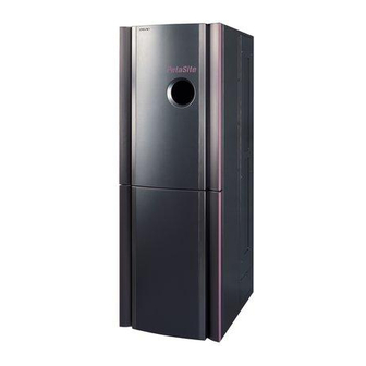
Section 1 Overview This manual describes how to install the PetaSite S-series Consolidated Storage Management System and applies models in the table below. The PetaSite S-series Consolidated Storage Management System is a tape library system for controlling many S-AIT (Super-Advanced Intelligent Tape) format (SAIT-1, SAIT-2) and LTO Ultrium format (LTO-3, LTO-4, and LTO-5) cartridges, and for storing, searching, recording and playing back large amounts of data at high speed. - Page 6 List of the corresponding models Model Name Over view Basic storage system Storage management system CSM-200B (SY) Up to 12 optional SAIT-1/SAIT-2 drive units can be installed (2 CSM-100B (SY) units minimum). CSM-60B (SY) The switching hub and terminal server are installed as the standard configuration.
- Page 7 . Linear Tape-Open, LTO, LTO Logo, Ultrium and Ultrium Logo are trademarks of Hewlett Packard Company, IBM Corporation, and Seagate Technology, Inc. in the United States and other countries. . PetaSite, PetaServer, PetaBack and S-AIT (SAIT-1, SAIT-2) are the trademarks of Sony Corporation. . Proliant is a registered trademark of HP.
-
Page 9: Tools
Section 2 Tools The tools for installation this system are listed in this section. You may use any equivalent item available in your market when Sony Part No. is not mentioned. Description Spec (Size, etc.) Sony part number Remarks 7 x 8 mm... -
Page 11: Unpacking
Section 3 Unpacking This section describes how to unpack and install this system at the installation location. It also describes the environment required for the those work. 3-1. Before Unpacking Before starting unpacking, prepare enough installation space described below. The dimensions and weight of this system, as well as the space required for installation, are described. -
Page 12: Space For Cable Routing
3-2. Unpacking Procedure and List of 3-1-3. Space for Cable Routing Accessories The console has openings/holes in the bottom of the front 3-2-1. Unpacking Procedure door side and the rear door side for the cable routing. Use the openings/holes in the bottom for routing external cables such as the power cable, network cable and data The console (main unit), slope and accessory box are cable to the console. - Page 13 3. Release the lock of the ten P-joints in the front, and 6. Open the bottom tray and remove the frame (frame remove the ten P-joints in the front starting from the side use). bottom P-joint, one after another. Frame (frame side use) P joint 4.
- Page 14 8. Remove the top pad in the upward direction. 11. Lower the adjuster foot in the bottom of the console 9. Remove the two corner pads (F) and the two corner until they touch the floor. Rotate the adjuster foot pads (R).
- Page 15 13. Raise the adjuster foot until the casters touch the floor. Then raise the adjuster foot until the casters are 20 mm At least three persons must work together for safety when above the top surface of the bottom tray as shown. bringing down the console from the bottom tray using the slope.
-
Page 16: Accessories
3-2-2. Accessories Basic storage system (For CSM-200B/100B/60B) PLUG HOLDER (B) (x2) CONNECTION CORD CONNECTION CONNECTION (DISPLAY CORD 1.5M CORD EXTENSION) (x1) (x1) (K/M EXTENSION) (x2) PLUG HOLDER (C) (x2) HEXAGON NUT (20) (x4) LICENSE SHEET (For CSM-200B/100B) OPERATION MANUAL WASHER (x4) PROGRAM DISK (OS) ASSY (Linux DVD) PROGRAM DISK (PSC) ASSY INSTRUCTION (LVD) - Page 17 Extension console (For CSM-200C/200D) (For CSM-200D) PLUG HOLDER (B) (x1) HEXAGON SOCKET BOLT (x8) PLUG HOLDER (C) (x1) HEXAGON NUT (20) (x4) WASHER (x4) GUIDE OPERATION INSTRUCTION (LVD) ACCESSORY BOX CSM-200...
-
Page 19: Installation
Section 4 Installation This section describes the installation procedure of the PetaSite S-series Consolidated Storage Management System including optional goods. Follow the installation procedure described below as it includes the important safety information such as prevention from falling. 4-1. Installation Space and Flow of Installation Procedure 4-1-1. -
Page 20: Flow Of Installation Procedure
4-1-2. Flow of Installation Procedure This section describes the installation flow chart to facilitate the installation. Click the desired installation process or click the desired item from index. Then the detailed installation procedure of the selected item appears. Opening the Outer Cabinets (Refer to Section 4-2-1.) Removing the Shipping Metal Fixture The shipping metal fixture must be removed at the time... -
Page 21: Installation Procedure
4-2. Installation Procedure 4-2-1. Opening the Outer Cabinets 1. Front Door (1) Loosen the two screws of the door fixed plate, that are locking the lower front door. (2) Move the door fixed plate toward left and tighten the two screws. Front door Door fixed plate Release... - Page 22 (4) Open the upper front door in the same way as the lower front door. (5) Install the door fixed plate of the upper front door of the Basic storage system at the position shown by (*1). Front door Install the door fixed plate here. (*1) View in the direction of arrow A.
- Page 23 2. Rear Door/Bin Door (1) Loosen the six screws (with drop-safe). Old type RK4 x 20 (with drop-safe) Rear door RK4 x 20 (with drop-safe) New type RK4 x 20 (with drop-safe) Rear door RK4 x 20 (with drop-safe) CSM-200...
- Page 24 (2) Open the rear door. Rear door CSM-200...
- Page 25 (3) Loosen the four hexagon socket bolts (with drop-safe) of the bin door. (4) Hold the handle and open the bin door. Bin door Hexagon socket bolts (with drop-safe) Handle Hexagon socket bolts (with drop-safe) Rear door CSM-200...
- Page 26 3. Front Inner Panel (1) Open the front door. (2) Loosen the six screws (with drop-safe). (3) Remove the Front inner panel. RK4 x 25 (with drop safe) RK4 x 25 (with drop safe) RK4 x 25 (with drop safe) Front inner panel 4.
-
Page 27: Removing The Shipping Metal Fixture
4-2-2. Removing the Shipping Metal Fixture The transfer assembly and the carrier assembly are fixed inside the basic storage system by the shipping metal fixtures to avoid damage during transportation. This section describes the procedure of removing these shipping metal fixtures. If you are going to install the Basic storage system and the extension console at the same time, remove the shipping metal fixture after connection of the extension console is complete. - Page 28 3. Y-axis (1) Remove the two hexagon socket bolts (a). (2) Remove the two hexagon socket bolts (b) and remove the shipping (C). (b) M4 x 8 Shipping (C) (a) M4 x 8 4-10 CSM-200...
- Page 29 Storage procedure For the models with one of the following serial numbers, the shipping metal fixtures and the fixing bolts can be stored in the console. Target serial numbers: CSM-200B : from initial production CSM-100B : from initial production CSM-60B : from initial production CSM-200BF : 1000008 and later CSM-200BS : 1001120 and later...
- Page 30 3. Shipping metal fixtures on the Y-axis (1) Install Shipping (C) in the orientation shown in the figure onto the floor with the two hexagon socket bolts. (2) Install the two hexagon socket bolts to the positions shown in the figure. Shipping (A) M4 x 8 M4 x 8...
-
Page 31: Installing The Basic Storage System
4-2-3. Installing the Basic Storage System The following description applies when installing the Basic storage system only or when installing a single extension console only. Determining the installation location Determine the installation location and move the Basic storage system. Free space allowing to open/close the door is necessary during inspection or maintenance. (Refer to 4-1-1. - Page 32 Installing the basic storage system when connecting the extension consoles in the range of 2 to 7 extension consoles Determining the installation location Determine the installation location and move the basic storage system. Free space allowing to open/close the door is necessary during inspection or maintenance. (Refer to 4-1-1.
- Page 33 3. Check that height of point [A] is 275 mm above the floor. If height of point [A] is not 275 mm, adjust height as follows. Loosen the four nuts of the respective casters with open-end wrench. Adjust height of the respective casters with hexagon Allen wrench (diagonal size: 10 mm). (One full clockwise rotation of a caster by 360d raises the console by 2.5 mm.
- Page 34 5. Rotate the adjuster foot by hand until the feet of the basic storage system contact the floor, and completely ground them on the floor. 6. Install tentatively the washers and hexagon nuts (20) that are supplied with the extension console, in the screwed portions of the four adjuster feet.
- Page 35 9. Install the rails for PCU that are removed in Step 2. (1) Align the lowest hole of the rack mount plates and the lower fixed pin of the slide mounting brackets. (2) Slide the slide mounting brackets to the point where the lock plates on the front and the back are locked.
-
Page 36: Extension Console
4-2-4. Extension Console This section describes the procedure of expanding the extension console. The extension kit is required to connect the Extension console. Prepare the extension kit as needed by referring to the table below. Number of Extension Required options consoles to be connected Extension belt kit. - Page 37 Expanding procedure 1. Remove the six screws (with drop-safe), and remove the side panel (R) assy of the Basic storage system. M4 x 20 (with drop-safe) M4 x 20 (with drop-safe) Side panel (R) ASSY 2. Remove the side panel retainer of the Basic storage system. (1) Remove the two screws and remove the side panel retainer (upper).
- Page 38 When Expanding a Single Extension Console 5. Expand the extension console to the Basic storage system. (1) Adjust height of the four casters of the extension console until the two reference pins of the extension console match the reference holes of the Basic storage system. Then, expand the extension console to the Basic storage system while aligning the two reference pins of the extension console with the corresponding reference holes of the Basic storage system.
- Page 39 6. Tighten both of the Basic storage system and the extension console with the eight hexagon head cap bolts (M4 x 8) supplied with the extension console. 7. Connect the two flat cables (50-pins and 26-pins) coming from the Basic storage system to the connectors of the extension console.
- Page 40 When Expanding the extension consoles in the Range of 2 to 7 Extension Consoles . When expanding two or more consoles, the Basic storage system must satisfy the conditions specified in “Installing the Basic storage system (Installing the Basic storage system when expanding the extension consoles in the range of 2 to 7 extension consoles)”...
- Page 41 6. Tighten both of the Basic storage system and the extension console with the eight hexagon head cap (M4 x 8) bolts supplied with the extension console. 7. When more than one consoles are expanded each other, use a caliper and measure the dimensions between [A]-[A] of the X-reference pins of next consoles.
- Page 42 9. If the accumulated difference between [A]-[A] at both of the upper side (L1) and the lower side (L2) of the X-reference pin exceeds 2 mm, take the following measures. (1) Remove the eight hexagonal head bolts and the two flat cables of the extension console at the point where the accumulated difference exceeds 2 mm.
- Page 43 11. Fixing the extension consoles (1) Rotate all of the adjuster foot of the expanded extension consoles by hand down to the height of casters until the feet of the Basic storage system contact the floor, and completely ground them on the floor.
- Page 44 12. Connecting the X Rail (top) Do not touch the linear way of the X rail with bare hands. Doing so may cause rust and prevent from smooth operation of the transfer. (1) Remove the two hexagon head cap bolts (a) securing the X rail of the extension console side. (2) Loosen the five hexagon head cap bolts (b) and the two hexagon head cap bolts (e) of the connection block and those of the X rail (top).
- Page 45 (5) Tighten the hexagon head cap bolt (g) of the connecting block of the Basic storage system side. Then align the X rail (top) of the extension console side with the reference surface. Side of the extension Side of the Basic storage system console (g) M4 x 16 X rail (top)
- Page 46 (8) Tighten the hexagon head cap bolt (c) of the connecting block of the extension console side. (9) Tighten the hexagon head cap bolt (a) (of the extension console side) that was provisionally tightened in step (4). (10) Tighten the nut securing the hexagon head cap bolt (c) so that the bolt will not become loose. (11) Tighten the hexagon head cap bolt (d) so that the X rail (top) contacts the reference pin.
- Page 47 13. Connecting the X Rail (Bottom) (1) Loosen the four hexagon head cap bolts (M4 x 20) securing the X rail (bottom) of the extension console side. Be careful not to loosen the hexagon head cap bolts (M4 x 20) excessively, otherwise the plate nut may come off.
- Page 48 14. Removing the X Belt Do not apply excessive force to the drive block and fragile parts which can be easily damaged. (1) Remove the four screws (M4 x 8), and move the X stoppers (T)/(B) from the Basic storage system to the same position of the end console (the extension console that is expanded last).
- Page 49 (3) Loosen the hexagonal head cap bolt (c) of the upper X tension assembly to reduce the load on the spring. (4) Remove the two hexagonal head cap bolts (d) securing the upper X tension assembly, and remove the X tension assembly. (5) Loosen the hexagonal head cap bolt (a) securing the X pulley assembly (top).
- Page 50 15. Installing the X Belt (1) Route the optional X belt between the synchro shaft and the X pulley assemblies (top)/(bottom). . Prepare the number of optional X belts corresponding to the number of extension consoles that you are going to expand. Cut the X belt at the marked position with nippers as follows. Parts required and the cutting position .
- Page 51 (2) Confirm that the X belt (top) is not twisted. After confirming that, align the six gear teeth at both ends of the X belt (top), with the X belt holder bracket and with the fixing belt (X) that were removed in step (11) of “14.
- Page 52 (6) Loosen the three hexagon socket bolts (M4 x 14) that are secured in step (4), to the extent that the X pulley-fixing table can be moved to the right and left. Tighten the adjustment screw until the stepped portion of the tension adjustment shaft is aligned with the end surface of the X pulley assembly.
- Page 53 (8) Confirm that the X belt (bottom) is not twisted. Engage the six teeth of an end of the belt with the six teeth of the other end of the belt in between the X belt holder bracket and the X belt holder that are removed in step (10) of “14.
- Page 54 (13) Install the X belt holder bracket in the X slider (bottom) using the two hexagonal head cap bolts (M5 x 12). M5 x 12 Washer (D5) X belt holder bracket X slider (bottom) 16. Remove the X-axis shipping metal fixture and the Y-axis shipping metal fixture. (Refer to “4-2-2. Removing the Shipping Metal Fixture”.) 17.
- Page 55 Measuring method using the tension scale (J-6461-340-A) Hook the fan tension scale on the front side (side of the rear door) of the X belt, and measure the tension. (1) Move the transfer assembly to the position as (400 mm) specified in the illustration. (2) Place the fan tension scale on the center of the X belt in the lengthwise direction.
- Page 56 18. Phase Adjustment (1) Move the transfer to the extension console side. Move the phase adjustment pin of the Basic storage system to the adjustment position. Phase adjustment pin (2) Push the X slider (top) and the X slider (bottom) against the phase adjustment pin. Then, check the clearances at the top and bottom satisfy the specification.
- Page 57 (3) Return the phase adjustment pins to their original positions. Tightening torque: 0.8 N.m (8 kgf.cm) Be sure to return the phase adjustment pins to their original positions upon completion of the phase adjustment. 19. Movement check of X belt Hold the Y rail, and check the followings during its right and left movements in the X direction.
- Page 58 21. Install the CSMA-CBLS (This work is required only when 2 to 3 Extension consoles are expanded.) . Do not touch the linear way of the transfer with bare hands during installation. Doing so may cause rust and prevent from smooth operation of the transfer. .
- Page 59 (4) Remove the four screws and the X cable bracket (BASIC). X cable bracket (Basic) PSW4 x 12 PSW4 x 12 Y base assembly (lower) (5) Disconnect the harnesses from the connectors (CN300, CN301 and CN302) on the CB-120 board. CN302 CN300 CN301...
- Page 60 (7) Remove the two screws, and the CB-120 board and the CB-120 bracket from the Basic storage system. PWH4 x 8 PWH4 x 8 CB-120 bracket CB-120 board (8) Install the CB-120 board and the CB-120 bracket removed in step (7) to the expanded first extension console.
- Page 61 (13) Install the Guide channel (BASIC) in the Basic storage system and in the first extension console with two screws (PWH4 x 8). Install the Guide channel so that the reference holes on part A face toward the Basic storage system. Be careful not to pinch the harness beneath the Guide channel (Basic).
- Page 62 (16) Draw out the cable from the hold of the Guide channel (EX3). Draw out the inside cable first from the bent portion. Then draw out the outside cable. It facilitates the work of drawing out the cables. Guide channel (EX3) Cable (inside) Cable (outside) (17) Slide the X cable until the reference pin comes to the portion C while being careful so that dowel...
- Page 63 (19) Connect the Robot cable that is drawn out in step (16) to the connector (CN302) on the CB-120 board. CN302 CB-120 board (20) Fix the X cable bracket (CBL-F) and the Guide channel (EX3) to the console respectively with the screw (PWH4 x 8).
- Page 64 (23) Put the cables that are disconnected in step (3), into the wiring binders. Confirm that the two cables are not twisted and are laid parallel. (24) Connect the Robot cable to the connector (CN100) on the CB-117 board. (25) Fix the cable using the new binding band supplied, at the position where the binding band was removed in step (2).
- Page 65 22. Install the CSMA-CBLL (This work is required only when 4 to 7 Extension consoles are expanded.) . Do not touch the linear way of the transfer with bare hands during installation. Doing so may cause rust and prevent from smooth operation of the transfer. .
- Page 66 (4) Remove the four screws and the X cable bracket (BASIC). X cable bracket (Basic) PSW4 x 12 PSW4 x 12 Y base assembly (lower) (5) Disconnect the harnesses from the connectors (CN300, CN301 and CN302) on the CB-120 board. CN302 CN300 CN301...
- Page 67 (7) Remove the two screws, and the CB-120 board and the CB-120 bracket from the Basic storage system. PWH4 x 8 PWH4 x 8 CB-120 bracket CB-120 board (8) Install the CB-120 board and the CB-120 bracket removed in step (7) to the expanded third extension console.
- Page 68 (13) Install the Guide channel (BASIC) in the Basic storage system and in the first extension console with two screws (PWH4 x 8). Install the Guide channel so that the reference holes on part A face toward the Basic storage system. Be careful not to pinch the harness beneath the Guide channel (Basic).
- Page 69 (16) Check that the connection of the Runner flex around the X cable is not disconnected or loose at any position. Then rotate the X cable bracket (CBL-F) in the direction of the arrow A in the Guide channel (EX3). Insert the protrusions into the two slits.
- Page 70 (19) Install the Guide channel (EX3) in the third Extension console and in the fourth Extension console as shown in the illustration. Align the two M4-screw holes on the floor with the reference hole and the long slot of the portion A at both ends of the Guide channel (EX3). When installing it, the Guide channel should be directed so that the reference hole of portion A faces toward the Basic storage system.
- Page 71 (22) Tighten finally the screw (PWH4 x 8) that has provisionally fixed the Guide channel (EX3) in step (19). (23) Install the X CABLE BRACKET (CBL-YR) with the four screws (PSW4 x 12) that are removed in step (4) and the screw (PSW4 x 12) that is supplied with the equipment. At this time, check that the two position-setting dowels have entered the two holes respectively.
- Page 72 (27) Attach the X cable cover with two screws (PWH4 x 8). PWH4 x 8 X cable cover Guide channel (EX3) (28) Install the Idler (top) assembly on top of the extension console with the two screws (PWH4 x 8). If the number of extension consoles is four or five, install the Idler (top) assembly on the third extension console.
- Page 73 (32) Check that the connection of the Runner flex around the X cable is not disconnected or loose at any position. Check whether the transfer unit moves freely from an end stopper of the connected rail to the other end stopper of it. Especially, confirm that the cable unit that runs from X CABLE BRACKET (CBL-YR) to CB-117 does not touch the walls when the transfer unit is moved to the basic console.
-
Page 74: Prevention From Falling
4-2-5. Prevention from Falling Securing the consoles to the floor is recommended to prevent the consoles from falling at the casualties such as earthquake, after installing the basic storage system and the extension consoles. Two methods of securing the consoles are prepared. One method is to secure the consoles to the ceiling and pillars. The other method is to secure the consoles to floor. - Page 75 2. Securing the consoles to floor The two screw-holes for installing the fixing metal are provided in the bottom of the front and rear respectively of each console. Install the fixing metal by referring to the installation example shown below, and secure the console to floor.
-
Page 76: Installing The Pcu
4-2-6. Installing the PCU This server uses the Proliant DL360 G3/G4/G4p/G5/G6/G7 made by HP. Therefore, no warranty is provided by Sony. The user can receive the support anywhere in the world by connecting the maintenance contract with the local HP company. - Page 77 3. Ambient temperature By referring to the table below, set the ambient temperature, check whether the PC-server cluster can be installed in the console, and designate the direction of the fiber channel switch. The following table shows the ambient temperatures for the both old and new types of the console. .
- Page 78 Old type New type Bottom of Rear door Addition of opening for server area Inside of front side Blank panel (1U) Deletion of Blank panel (1U) Bottom of Front door (lower) Addtion of air holes 4-60 CSM-200...
- Page 79 Installing Procedure When the Proliant DL360 G3 made by HP is included 1. Unpack the PCU main unit and the hard disk. 2. Take the KM extension cable and the monitor extension cable out from the accessory box. 3. Open the front door (bottom) and the rear panel of the console. (Refer to “4-2-1. Opening the Outer Cabinets”.) 4.
- Page 80 (2) Install the rail to the topmost holes of the rack installing plate with its front side facing inward. Install the rear side of the rail first to the plate holes, and then install the front side by contracting the rail itself. Rear side Fit in Front side...
- Page 81 6. Install the monitor, the mouse and the keyboard. Connect them to the PCU using the extension cables (KM extension cable and the monitor extension cable) supplied with the PCU and packed in the accessory box. 7. Connect the network cable on the Ethernet hub to the PCU as shown in Fig. 1. (Connection of the PCU to the Ethernet HUB is also described in “4-2-7.
- Page 82 8. Installing the hard disk in the PCU (1) Remove the blank panel from the drive bay of the PCU. (2) While pushing the LOCK buttons on the both side of the blank panel in the direction of the arrow 1, hold the blank panel. (3) Draw the blank panel out from the drive bay in the direction of the arrow 2.
- Page 83 When the Proliant DL360 G4/Proliant DL360 G4p made by HP is included 1. Unpack the PCU main unit. 2. Take the KM extension cable and the monitor extension cable out from the accessory box. 3. Open the front door (lower) of the console. (Refer to “4-2-1. Opening the Outer Cabinets”) 4.
- Page 84 7. Install the monitor, the mouse and the keyboard. Connect them to the PCU using the extension cables (KM extension cable and the monitor extension cable) supplied with the PCU and packed in the accessory box. 8. Connect the network cable on the Ethernet hub to the PCU as shown in Fig. 1. (Connection of the PCU to the Ethernet hub is also described in “4-2-7.
- Page 85 9. Installing the hard disk in the PCU (1) Remove the blank panel from the drive bay of the PCU. (2) While pushing the LOCK buttons on the both side of the blank panel in the direction of the arrow 1, hold the blank panel. (3) Draw the blank panel out from the drive bay in the direction of the arrow 2.
- Page 86 When the Proliant DL360 G4/Proliant DL360 G4p made by HP is procured at the store Target serial numbers: CSM-200B : from initial production CSM-100B : from initial production CSM-60B : from initial production CSM-200BF : 1011347 and later CSM-200BS : 1012405 and later CSM-100BF : 1012678 and later CSM-100BS : 1012847 and later CSM-60BF :...
- Page 87 5. Attach the new HBA board to PCU. (1) Lift the lock lever on the top cover in the direction of the arrow A. (2) Slide the top cover in the direction of the arrow B, and remove it in the direction of the arrow C. Lock lever Top cover (3) Loosen the four screws (with drop-safe) sufficiently, and remove the frame in the direction of...
- Page 88 (4) Insert the HBA board into the slot of the frame. HBA board Slot (5) Insert the frame on which the HBA board is attached in step (4) into the slot, and secure it with the screw (with drop-safe). Fixed screw (with drop-safe) Fixed screw (with drop-safe)
- Page 89 6. Install the rails supplied with the PCU to the PCU main unit. (1) Align the protrusions on the PCU main unit with the holes on the rails. (2) Press the rails on the PCU and slide them toward the rear side of the PCU to lock them. Rail Rail 7.
- Page 90 When the Proliant DL360 G5 made by HP is procured at the store Target serial numbers: CSM-200B : from initial production CSM-100B : from initial production CSM-60B : from initial production CSM-200BF : 1011347 and later CSM-200BS : 1012405 and later CSM-100BF : 1012678 and later CSM-100BS : 1012847 and later CSM-60BF :...
- Page 91 5. Attach the Host Bus Adaptor (HBA) to the PCU unit. (1) Lift the lock lever on the top cover in the direction of the arrow A. (2) Slide the top cover in the direction of the arrow B, and remove it in the direction of the arrow C. Lock lever Top cover (3) Loosen the four screws (with drop-safe) sufficiently, and remove the frame in the direction of...
- Page 92 (4) Insert the PCI-X Express expansion board into the slot of the frame with the screws and insert HBA board into the slot of the PCI-X Express expansion board. Frame Fixed screw PCI-X/PCI-Express HBA board Fixed expansion board screw (5) Insert the frame on which the HBA board is attached in step (4) into the slot, and secure it with the screw (with drop-safe).
- Page 93 6. Install the rails supplied with the PCU to the PCU main unit. (1) Align the protrusions on the PCU main unit with the holes on the rails. (2) Press the rails on the PCU and slide them toward the rear side of the PCU to lock them. Rail Rail 7.
- Page 94 9. Install the monitor, the mouse and the keyboard. Connect them to the PCU using the extension cables (KM extension cable and the monitor extension cable) supplied with the PCU and packed in the accessory box. 10. Connect the network cable on the Ethernet hub to the PCU as shown in Fig. 1. (Connection of the PCU to the Ethernet HUB is also described in “4-2-7.
- Page 95 11. Installing the hard disk in the PCU (1) Remove the blank panel from the drive bay of the PCU. (2) While pushing the LOCK buttons on the both side of the blank panel in the direction of the arrow 1, hold the blank panel. (3) Draw the blank panel out from the drive bay in the direction of the arrow 2.
- Page 96 When the Proliant DL360 G6 made by HP is procured at the store Target serial numbers: CSM-200B : from initial production CSM-100B : from initial production CSM-60B : from initial production CSM-200BF : 1011347 and later CSM-200BS : 1012405 and later CSM-100BF : 1012678 and later CSM-100BS : 1012847 and later CSM-60BF :...
- Page 97 5. When option DKNB-200S (SCSI HBA) is installed, attach the Host Bus Adaptor (HBA) to the PCU unit. (1) Lift the lock lever on the top cover in the direction of the arrow A. (2) Slide the top cover in the direction of the arrow B, and remove it in the direction of the arrow C. Lock lever Top cover (3) Loosen the four screws (with drop-safe) sufficiently, and remove the frame in the direction of...
- Page 98 (4) Insert the PCI-X Express expansion board into the slot of the frame with the screws and insert HBA board into the slot of the PCI-X Express expantion board. Frame Fixed screw PCI-X/PCI-Express HBA board Fixed expansion board screw (5) Insert the frame on which the HBA board is attached in step (4) into the slot, and secure it with the screw (with drop-safe).
- Page 99 6. Install the rails supplied with the PCU to the PCU main unit. (1) Align the protrusions on the PCU main unit with the holes on the rails. (2) Press the rails on the PCU and slide them toward the rear side of the PCU to lock them. Rail Rail 7.
- Page 100 9. Install the monitor, the mouse and the keyboard. Connect them to the PCU using the extension cables (KM extension cable and the monitor extension cable) supplied with the PCU and packed in the accessory box. 10. Connect the network cable on the Ethernet hub to the PCU as shown in Fig. 1. (Connection of the PCU to the Ethernet HUB is also described in “4-2-7.
- Page 101 11. Installing the hard disk in the PCU (1) Remove the HDD Blank from the drive bay of the PCU. (2) While pushing the LOCK buttons on the both side of the HDD Blank in the direction of the arrow 1, hold the HDD Blank. (3) Draw the HDD Blank out from the drive bay in the direction of the arrow 2.
- Page 102 When the Proliant DL360 G7 made by HP is procured at the store Target serial numbers: CSM-200B : from initial production CSM-100B : from initial production CSM-60B : from initial production CSM-200BF : 1011347 and later CSM-200BS : 1012405 and later CSM-100BF : 1012678 and later CSM-100BS : 1012847 and later CSM-60BF :...
- Page 103 5. When option DKNB-200S (SCSI HBA) is installed, attach the Host Bus Adaptor (HBA) to the PCU unit. (1) Lift the lock lever on the top cover in the direction of the arrow A. (2) Slide the top cover in the direction of the arrow B, and remove it in the direction of the arrow C. Lock lever Top cover (3) Loosen the four screws (with drop-safe) sufficiently, and remove the frame in the direction of...
- Page 104 (4) Insert the PCI-X Express expansion board into the slot of the frame with the screws and insert HBA board into the slot of the PCI-X Express expantion board. Frame Fixed screw PCI-X/PCI-Express HBA board Fixed expansion board screw (5) Insert the frame on which the HBA board is attached in step (4) into the slot, and secure it with the screw (with drop-safe).
- Page 105 6. Install the rails supplied with the PCU to the PCU main unit. (1) Align the protrusions on the PCU main unit with the holes on the rails. (2) Press the rails on the PCU and slide them toward the rear side of the PCU to lock them. Rail Rail 7.
- Page 106 9. Install the monitor, the mouse and the keyboard that are compatible with USB. Also, connect them to the PCU using the USB compatible extension cables. (Refer to Fig. 1.) 10. Connect the network cable on the Ethernet hub to the PCU as shown in Fig. 1. (Connection of the PCU to the Ethernet HUB is also described in “4-2-7.
- Page 107 11. Installing the hard disk in the PCU (1) Remove the HDD Blank from the drive bay of the PCU. (2) While pushing the LOCK buttons on the both side of the HDD Blank in the direction of the arrow 1, hold the HDD Blank. (3) Draw the HDD Blank out from the drive bay in the direction of the arrow 2.
-
Page 108: Installing The Hub
4-2-7. Installing the Hub The Hub is packed in the separate package from that of the console. This section describes the procedure of installation starting from unpacking up to installation in the basic storage system. When using a commercially-available switching hub : . - Page 109 5. Connect the network cable and the DC power cable that have already been installed earlier inside the console, to the Hub. Network cable TS assembly TS assembly TS assembly DC power cable 6. Install the Hub holder that was removed in step 4, and the Hub into the console. PWH4 x 8 PWH4 x 8 Hub holder...
-
Page 110: Installing The Drive Unit
4-2-8. Installing the Drive Unit S-AIT drive (CSMA-DR100S/CSMA-DR130F/CSMA-DR200S/CSMA-DR230F) To install LTO (LTO-3, LTO-4, and LTO-5) drive units, install CSMA-AIL2F referring to “4-3-3. Extension Drive Unit” - “LTO drive,” and then install the drive unit using the following procedure. It enables installation of the maximum 12 units of the S-AIT drive units in the basic storage system and the drive console. - Page 111 (2) Insert the drive unit while aligning the drive unit with the guide, and install the drive unit using the screw removed in step (1). Insert the drive unit gently to avoid shock to the drive and connector portions. Connect the connector of the drive to that of the main unit while aligning them with each other.
-
Page 112: Pcu Setup
4-2-9. PCU Setup This server uses the Proliant DL360 G3, G4, G4p, G5, G6, and G7 made by HP. It means that Sony is not in the position to guarantee but any client can receive the support all over the world by connecting the maintenance contract with the local HP company. - Page 113 For Proliant DL360 G5 Network cable Power cord Ethernet hub Monitor extension cable Primary AC power source KM extension cable Mouse cable Keyboard cable Monitor cable Monitor Mouse Keyboard For Proliant DL360 G6 Network cable Power Ethernet hub cord Primary AC power source KM extension cable Monitor extension...
- Page 114 For Proliant DL360 G7 Network cable Power Ethernet hub cord Primary AC power source USB extension cable Monitor extension cable Keyboard cable Mouse cable Monitor cable Monitor Keyboard Mouse Setup Procedure 1. RAID setup (1) Turn on the power switch of the PCU main unit. (2) Press the F8 key to continue when the “Press <...
- Page 115 2. iLO setup The iLO is available for each loaded server. DL360G4, DL360G4p: iLO DL360G5/G6: iLO2 DL360G7: iLO3 The following functions are supplied by HP. Note that the HP’s supply method of these functions may be changed or they may be unavailable. .
- Page 116 3. BIOS setup Steps (2) through (5) are required for Proliant DL360 G3 only made by HP. (1) Execute “ROM-Based Setup Utility” by pressing the F9 key in the “System currently configured for Linux” screen. (2) Select “System Option” from the menu. (3) Select “OS Selection”...
- Page 117 4. Operating system installation 4-1. PetaApp Linux Installation Procedure (1) Preparation (a) Record the serial number on the main unit of CSM-200B/200BF/200BS/100B/100BF/100BS/ 60B/60BF/60BS. (b) For only PSC V6.10 or earlier, “PetaApp Maintenance Tool” is required to set the host ID. Contact the service section of the retailer where you purchased this product.
- Page 118 For only PSC V6.10 or earlier, perform the steps (5) to (7) by PetaBack/PetaServe in PC server. (For PSC V6.20 or later, the host ID is set when installing the PSC.) Set the host ID using the “PetaApp Maintenance Tool” prepared in (1). Mount floppy “PetaApp Maintenance Tool”, open the terminal window, start the /mnt/floppy/ pahostid in the floppy, sequential No.
- Page 119 4-2. Starting PetaApp Linux Perform settings using the following procedure. If no display appears, refer to “ Note 1 ” below. (1) When you want to log into the root account Enter Username “root”, and Password “sony2002”. (2) When you want to change the root password Use the “passwd”...
- Page 120 Enter “1” and then continuously the serial number of the basic console. For example, if the serial number of the basic console is Sony PetaApp Server Install is Complete “1009186”, enter “11009186”. (6) Shutdown. When the number is not displayed in [ ] or incorrect, execute the painstall again.
- Page 121 Select (1/2/3/4/q) : Enter “4” (Selects the CSM) Input the serial number of Basic Console : [ ] : Enter the serial number (For PetaApp/PSC V6.20 or later) Blank (no input) is OK. Sony PetaApp Server Install is Complete (5) Shutdown. 4-103 CSM-200...
- Page 122 (4) When the screen “PetaApp” is not open, double-click the “PetaApp” icon to open the “PetaApp”. Click the “Utility” to open the “PetaApp Utility” screen, and select the “Mode: Administrator” on the upper-right of the screen. (the default password is “sony”). (5) Click the “PetaApp Utility” icon, and select the “SNMP” tag.
- Page 123 (2) Click the “PetaSite” or “Monitor” on the PetaApp screen. (3) Change the mode to Administrator at “PSC (Monitoring & Maintenance Terminal)” screen (the default password is “sony”). (4) Select “Setup..” “PSC” from the pull-down menu, and select the “Communication” tag.
- Page 124 Open the terminal window. When a mount path has been created in the "/media" directory on the window, the USB memory can be used. An example of Sony Poket Bit /media/usbdisk/ To remove the USB memory, be sure to unmount it by entering as follows: # unmount /media/xxx/ If you do not log into the root account, the USB memory is not automatically mounted.
-
Page 125: Installing The Optional Equipment
4-3. Installing the Optional Equipment 4-3-1. Power Supply CSMA-PSL (for robot) 1. Open the front door. (Refer to “4-2-1. Opening the Outer Cabinets”.) 2. Remove the four screws (PWH4 x 8) and remove the blank panel (24 V). PWH4 x 8 Blank panel (24V) PWH4 x 8... - Page 126 CSMA-PSD (for drive) 1. Open the front door. (Refer to “4-2-1. Opening the Outer Cabinets”.) 2. Remove the two screws (PWH3 x 5) and remove the blank panel (12 V). Blank panel (12V) PWH3 x 5 3. Insert the CSMA-PSD and install it using the two screws that were removed in step (2). CSMA-PSD PWH3 x 5 4.
-
Page 127: Csma-Dif (Drive Interface)
4-3-2. CSMA-DIF (Drive interface) 1. Open the front door. (Refer to “4-2-1. Opening the Outer Cabinets”.) 2. Loosen fully the two screws with drop-safe of the IF boards in the T (S) slot and B (S) slot. Then, draw the IF boards out from the T (S) slot and B (S) slot. IF boards 3. - Page 128 8. Remove the front inner panel. (Refer to “4-2-1. Opening the Outer Cabinets”.) 9. Connect the harness that has already been installed earlier inside the console, to the TS ASSY. 10. Install the TS ASSY in the console using the three screws supplied. TS ASSY PWH 4 x 8 Harness...
- Page 129 Initial Setup of PSC2 V4, V5 and V6 (Not required for PSC2 V3) 1. From the Setup Menu of MMT, select “PSC”. Open the Setup PSC screen, and select the “Communication” tag. 2. Select the line of “MIB-R”. Press the “Revise” button to open the Communication screen. 3.
-
Page 130: Extension Drive Unit
4-3-3. Extension Drive Unit S-AIT drive (CSMA-DR100S/CSMA-DR130F/CSMA-DR200S/CSMA-DR230F) It enables installation of the maximum 12 units of the S-AIT drive units in the basic storage system and the drive console. 1. Open the front door. (Refer to “4-2-1. Opening the Outer Cabinets”.) 2. - Page 131 (2) Insert the drive unit while aligning the drive unit with the guide, and install the drive unit using the screw removed in step (1). Insert the drive unit gently to avoid shock to the drive and connector portions. Connect the connector of the drive to that of the main unit while aligning them with each other.
- Page 132 . The tape drive that can be installed in the PetaSite S200 series by using CSMA-AIL2F is IBM Total- Storage Ultrium Tape Drive, T1600P and T3000P. Regarding the versions of the firmware and hardware of the installable tape drive, consult with Sony service or sales representative.
- Page 133 2. Assembling the Drive Unit Mount the tape drive onto the attachment. (1) Remove the tape fixing all the harnesses to the attachment. (2) Remove the three screws and detach the rear bracket from the main unit of the attachment. Main unit Rear bracket (3) Fix the tape drive to the main unit of the attachment, using the supplied four screws (Nylok + B).
- Page 134 (5) Attach the rear bracket to the main unit of the attachment. Be sure that the harnesses are not caught in between. 1 Connect one end of the supplied FC relay harness to the tape drive. 2 Connect the other end of the harness to the FC relay adaptor on the rear bracket from the inside.
- Page 135 Extending the Drive Area (Basic storage system) When the basic storage system is shipped from the factory, the single row is assigned to the drive area, and the two rows are assigned to the bin areas. The bin areas can be changed to the drive areas as described below.
- Page 136 [When the drive reflector plate base type 1 is used] Drive reflector plate base (Type1) (4) Remove the two screws. Remove the first drive reflector plate base in the direction of the arrow. To remove the first drive reflector plate base, remove it in the way of removing the two protruded portions in the top of the first drive reflector plate base, from the slits as shown.
- Page 137 (6) Install the first drive reflector plate base so that the reflector plate faces toward the rear side. The reflector plate of the first drive reflector plate base must be installed in the way that the protruded portions a, b and c of the first drive reflector plate base enter the corresponding slits, and that the two dowels are aligned with the corresponding holes so that the positioning is correctly is set.
- Page 138 [When the drive reflector plate base type 2 is used] Drive reflector plate base (Type2) (4) Remove the two screws. Remove the first drive reflector plate base in the direction of the arrow. To remove the first drive reflector plate base, remove it in the way of removing the one protruded portion in the top of the first drive reflector plate base, from the slits as shown.
- Page 139 (8) Install the drives into the newly added drive area. Be sure to install the blank panels (drive) that are removed in step (3), in the blank slots in which drive is not installed, for safe operation of the system. (9) Remove the front inner panel.
-
Page 140: Psc Cluster Pcu
4-3-4. PSC Cluster PCU Refer to “4-2-6. Installing the PCU” for details. Preparation 1. Prepare an RS-232C crossover cable to connect the Primary and Secondary PC Servers. 2. Ask the User LAN administrator about three IP addresses on the User LAN side and each host name. (1) Primary User IP address and hostname (with a domain name) To be set for eth1 of the Primary PC Server. - Page 141 (2) Connect the Library and perform the following settings. Console Composition Drive Condition BIN Division Execute Mode Drive Setup Auto Head Cleaning 2. Change the Cluster settings to those for the Primary PC Server using the PetaApp GUI utility. (1) Start Utility from PetaApp GUI. (2) Change the mode to the Administrator mode.
- Page 142 (3) Log in to the system with “root”, and then change the Network setting. Click [GNOME Menu] (feet shaped icon). Click [System Setting] -> [open Network setting window] to open the Network setting window. Change the Network setting, including IP address and hostname, for the Secondary PC Server. *1 Set external IP addresses and hostnames in accordance with the User LAN.
- Page 143 6. Type “/psc/bin/pscend” on the terminal window. 7. Connect the network cable. 8. Connect Primary and Secondary using the RS-232C cross cable. 9. Type “/psc/bin/pscstart” on the terminal window. Checking Cluster status of Primary PSC2 1. Start Utility from PetaApp GUI. 2.
-
Page 144: Switch Setting
4-4. Switch Setting Switch setting when user wants to switch the bin areas and drive areas. Perform the switch setting on the CB-121 board, SE-717 board and SE-57 board when user wants to change the number of drive units in “4-3-3. CSMA-DR100S/CSMA-DR130F/CSMA-DR200S/CSMA- DR230F (Drive unit)”. - Page 145 Setting of the connected extension consoles Perform the switch setting on the SE-716 board when user wants to connect the Extension console in “4- 2-4. Extension console”. Only the switch setting for S101-1 should be performed. (Do not change the switch setting for S101-2.) SE-716 board (A side) : S101 Setting of the connected consoles (Consoles with the old-type reflector plate)
- Page 146 Setting of the Drive interface Perform the switch setting on the IF-923 board when user wants to add the CSMA-DIF (drive interface) in “4-3-2. CSMA-DIF (Drive interface)”. IF-121 board (A side) : S1100, S1102 S1100 S1102 IF-923 IF-923 (Redundant Drive Interface) Normal default setting when shipped from the factory (In the case when the two IF-923 boards are as a pair.) 8 7 6 5 4 3 2 1...
-
Page 147: Upgrading The Basic Storage System
Section 5 Upgrading the Basic Storage System The Basic storage system can be upgraded using the upgrade kit CSMU-100B or CSMU-200B. 5-1. Setting the License Key The root privilege of the PC and the administrator privilege of the PSC are necessary for this setting. Preparation before starting upgrade User must have obtained the License Key Code beforehand that are required for upgrade. -
Page 148: Operations On The Psc Screen
5-1-3. Operations on the PSC Screen 1. Right-click the mouse on the PSC screen to open the pop-up menu. Select “New Terminal” and open the terminal window of root. 2. Enter as shown below on the terminal screen and confirm either blank line or the license key (exam- ple: 1-12345-1234567890) appears. -
Page 149: Confirming The Configuration
5. When the MMT Sign In screen is open, enter as shown below and press the “OK” button. Password:sony (default password when shipped from the factory). 6. Click “Setup” in the top left of the PSC (MMT) screen to open the pull-down menu. Select “Console Composition”... -
Page 151: Power Supply Cable And Ups
Section 6 Power Supply Cable and UPS Introduction No power cord is supplied with the CSM-200. Prepare power cords beforehand. The CSM-200 is supplied in two different versions depending on the internal power supplying system of the CSM-200. Refer to the illustration below to check the required number of the power cords. (1) Cables for console Fig. -
Page 152: Power Cord
6-1. Power Cord 6-2. How to Use the Plug Holder Protect the plug using the plug holder so that the plug Be sure to use the equipment within the specified range of cannot be easily removed from AC outlet. power supply voltage. Power voltage : (AC100 V to 200 V) ±... -
Page 153: Connecting The Ups
6-3. Connecting the UPS There are two types of the CSM-200 depending on the internal power supply system; one type of the CSM-200 contains the single power system while the other type contains the dual power system. When using the UPS, check the system status described later and connect it correctly. UPS (Uninterruptible Power Supply) The UPS protects data from damage or devices from malfunction. - Page 154 (2) Connecting the CSM-200 system that contains the single input power system, to the When the shutdown function that enables status monitoring of the UPS is going to be used, connect the UPS by either one of the following methods. When enough capacity of the UPS can be secured, the connection using the method 1 is recommended, by which an integrated shutdown processing can be performed.
- Page 155 2. Connect the power cables of PSC and DRIVE to a single UPS, and connect the power cable of ROBOT to the other UPS. Breaker switch for DRIVE Breaker switch for ROBOT AC inlet for ROBOT AC inlet for DRIVE UPS2 - AC inlet for ROBOT UPS1 - AC inlet for DRIVE UPS1- PCU (redundant)
- Page 156 (3) Connecting the CSM-200 system that contains the dual input power systems to the If redundant power supplies for ROBOT and for DRIVE (product name: CSMA-PSL and CSMA-PSD) are not installed, only two cords are sufficient for use. When the shutdown function that enables status monitoring of the UPS is going to be used, connect the UPS by either one of the following methods.
- Page 157 2. Connect the power cables of PSC and DRIVE to a single UPS, and connect the power cable of ROBOT to the other UPS. AC inlet for DRIVE (redundant) AC inlet for ROBOT (redundant) AC inlet for ROBOT (standard) AC inlet for DRIVE (standard) UPS2 - AC inlet for ROBOT UPS1 - AC inlet for DRIVE...
-
Page 158: Settings To Supply Power To The Robot From The Psc And Other Ups
6-3-2. Settings to Supply Power to the ROBOT from the PSC and Other UPS To make the ROBOT of the PetaSite side monitor the UPS status, connect the interface cable to the UPS and set switch S1100-2 on the CPU-361 board. 1. -
Page 159: Input/Output Signals Of The Connector
6-4. Input/Output Signals of the Connector Harness (CB-UPS) (CB-121 board and connection) Parallel (D-sub 9-pin, Male) CSM-200BF Serial No. 1001081 to 1001098 CSM-200BF Serial No. 1000001 to 1000004 Parallel (D-sub 9-pin, Female) models other than the above 1(5) 6 (9) Parallel (D-sub 9pin) Numbers in ( ) are for male pins. - Page 160 Sample circuit Peta Site Robot UPS side CB-121 side Relay Signal from Harness (CB-UPS) 6-10 CSM-200...
-
Page 161: Operation Check
Section 7 Operation Check When all of the installation works are complete, perform the system initialization operation test using the test menu of the MMT (Monitoring and Maintenance Terminal) display. A test program for installation of Drive 1, 2 is available on PSC to perform operation test. Prepare one cartridge (compatible with the installed drives) on which barcode label is attached for the test program. - Page 162 2. Turn on the main power of a PSC and start up the MMT display. If the display is incorrectly set, the message “Out of Range” may appear and the display cannot be used correctly. In such a case, take the “ Note 1 ” measure. Note 1 Set X window again when the following symptoms occur in X window.
- Page 163 3. Enter the MMT display in the administrator mode. 4. Select “Program” of “Test” menu and open the Program display. 5. Input “test” into the Command box and set MMT into test mode. → When test mode is established, the MMT cannot be controlled any more from the host system. To exit the test mode, input “remote”...
- Page 164 7. Click the “Load” button and open “Csmcheckprg”. 8. Check for the program. Insert an S-AIT test cartridge into the top shelf of the upper input port. → System check program is the test program that has been already available on PSC. This program is created to check all operations of the PetaSite system.
- Page 165 9. Select the “Run” button and start executing the test program. → If any trouble occurs while the test is in progress, check error code of the PetaSite, perform the recovery operation and re-start the test program. (Refer to the PSC help for error coad.) 10.
-
Page 166: Precaution When Installing Cartridge
7-2. Precaution When Installing Cartridge This system controls the database of the cartridge by inserting the cartridge to or ejecting it from the I/O port. As a rule, insert the cartridge to the I/O port. Some specific bin area of the basic storage system cannot function as the storage location of the cartridges. - Page 167 The material contained in this manual consists of information that is the property of Sony Corporation. Sony Corporation expressly prohibits the duplication of any portion of this manual or the use thereof for any purpose other than the operation or maintenance of the equipment described in this manual without the express written permission of Sony Corporation.
- Page 168 CSM-200B (SY) CSM-200BF (SY) CSM-200BS (SY) CSM-100B (SY) CSM-100BF (SY) CSM-100BS (SY) CSM-60B (SY) CSM-60BF (SY) CSM-60BS (SY) CSM-200D (SY) Printed in Japan Sony Corporation CSM-200C (SY) E 2010. 12 32 9-968-766-02 ©2003...
Need help?
Do you have a question about the PetaSite CSM-200B and is the answer not in the manual?
Questions and answers