
Related Manuals for SCHUNK KLM Series


Summary of Contents for SCHUNK KLM Series
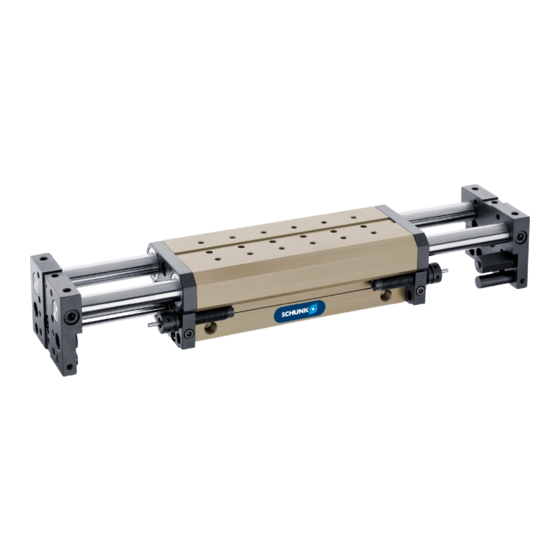
- Page 1 Translation of the original manual Assembly and operating manual Linear module...
- Page 2 Imprint Copyright: This manual is protected by copyright. The author is SCHUNK GmbH & Co. KG. All rights reserved. Any reproduction, processing, distribution (making available to third parties), translation or other usage - even excerpts - of the manual is especially prohibited and requires our written approval.
-
Page 3: Table Of Contents
Table of Contents Table of Contents General........................ 5 About this manual .................... 5 1.1.1 Presentation of Warning Labels ............... 5 1.1.2 Definition of Terms................... 6 1.1.3 Applicable documents ................ 6 1.1.4 Sizes ...................... 6 1.1.5 Variants..................... 6 Warranty ...................... 6 Scope of delivery .................... 6 Accessories ...................... - Page 4 Table of Contents Commissioning ....................... 21 Setting the speed.................... 22 Adjustment of the shock absorber strocke ............ 23 Handling ......................... 24 Final positions..................... 24 Intermediate stops ..................... 26 Dust cover...................... 27 Rod lock ...................... 27 Troubleshooting ..................... 29 Module does not move?.................. 29 End position signal not present ................
-
Page 5: General
General 1 General 1.1 About this manual This manual contains important information for a safe and appropriate use of the product. This manual is an integral part of the product and must be kept accessible for the personnel at all times. Before starting work, the personnel must have read and understood this operating manual. -
Page 6: Definition Of Terms
• Catalog data sheet of the purchased product * • Assembly and operating manuals of the accessories * The documents marked with an asterisk (*) can be downloaded on our homepage schunk.com 1.1.4 Sizes This operating manual applies to the following sizes: •... -
Page 7: Accessories
NI 30 KT NI 30 KT • Exact type designation of the compatible sensors see catalog. • Information on handling sensors is available at schunk.com or from SCHUNK contact persons. 03.00 | KLM | Assembly and operating manual | en | 389173... -
Page 8: Basic Safety Notes
Use of unauthorized spare parts Using unauthorized spare parts can endanger personnel and damage the product or cause it to malfunction. • Use only original spare parts or spares authorized by SCHUNK. 03.00 | KLM | Assembly and operating manual | en | 389173... -
Page 9: Environmental And Operating Conditions
• Ensure that no strong magnetic fields impair the function of the product. Contact your SCHUNK partner if the product is to be used in strong magnetic fields. 2.6 Personnel qualification Inadequate qualifications of the personnel... -
Page 10: Personal Protective Equipment
Basic safety notes 2.7 Personal protective equipment Use of personal protective equipment Personal protective equipment serves to protect staff against danger which may interfere with their health or safety at work. • When working on and with the product, observe the occupational health and safety regulations and wear the required personal protective equipment. -
Page 11: Transport
Basic safety notes 2.9 Transport Handling during transport Incorrect handling during transport may impair the product's safety and cause serious injuries and considerable material damage. • When handling heavy weights, use lifting equipment to lift the product and transport it by appropriate means. •... -
Page 12: Protection During Handling And Assembly
Basic safety notes 2.12.1 Protection during handling and assembly Incorrect handling and assembly Incorrect handling and assembly may impair the product's safety and cause serious injuries and considerable material damage. • Have all work carried out by appropriately qualified personnel. •... -
Page 13: Protection Against Dangerous Movements
Basic safety notes 2.12.3 Protection against dangerous movements Unexpected movements Residual energy in the system may cause serious injuries while working with the product. • Switch off the energy supply, ensure that no residual energy remains and secure against inadvertent reactivation. •... -
Page 14: Information About Special Dangers
Basic safety notes 2.13 Information about special dangers WARNING Risk of injury caused by crushing and impacts when moving the unit or attachments! Risk of injury due to attachments breaking or becoming loose! WARNING Risk of injury from objects falling and being ejected! Falling and ejected objects during operation can lead to serious injury or death. -
Page 15: Technical Data
Technical data 3 Technical data Size Ambient temperature [°C] 5 - 60 Fluid consumption / 1.13 12.57 10 mm stroke IP rating Noise emission [dB(A)] Pressure medium Compressed air (10µm): dry (non-condensing), oiled or not oiled Compressed air, compressed air quality according to ISO 8573-1:7 4 4 Min. -
Page 16: Assembly
Assembly 4 Assembly 4.1 Design precautions • A protective cover is recommended to minimize the risk of injury. • Ensure that loose, solid and / or attached parts are tightened. • Due to the high levels of kinetic energy, shock absorbers must be used •... -
Page 17: Connections
Assembly 4.3 Connections 4.3.1 Mechanical connection WARNING Risk of injury due to unexpected movements of the machine/ system! Moving the axes may cause serious injuries. Before performing assembly and adjustment works, switch off • the energy supply. Make sure there is no residual energy in the system. •... - Page 18 Assembly Assembly options KLM 25 Connection linear module Connection assembly On both connecting surfaces Assembly options KLM 50 Connection linear unit Connection assembly On both connection surfaces back Through bore in end plate and threaded into the base body (one side only) 03.00 | KLM | Assembly and operating manual | en | 389173...
- Page 19 Assembly Assembly options KLM 100 Connection linear module Connection assembly On both connection surfaces back Through bore in end plate and threaded into the base body (one side only) Assembly options KLM 300 Connection linear module Connection Assembly On both connection surfaces back Through bore in end plate and threaded into the base body (one side only) 03.00 | KLM | Assembly and operating manual | en | 389173...
-
Page 20: Pneumatic Connection
Assembly 4.3.2 Pneumatic connection WARNING Risk of injury due to unexpected movements! If the power supply is switched on or residual energy remains in the system, components can move unexpectedly and cause serious injuries. Before starting any work on the product: Switch off the power •... -
Page 21: Commissioning
Commissioning 5 Commissioning CAUTION Possible damage to the linear module when changing the air supply! Before operating with oil.-free air, the linear module should never be operated with lubricated air. CAUTION Possible damage to the linear module! If the unit moves too hard into the end position, the linear module may be damaged. -
Page 22: Setting The Speed
Commissioning 5.1 Setting the speed CAUTION Material damage due to erroneous settings! If the end position is approached too hard, the product may be damaged. Adjust exhaust throttle valve and shock absorber so that the • movement is braked smoothly. Close exhaust throttle valve completely. -
Page 23: Adjustment Of The Shock Absorber Strocke
Commissioning 5.2 Adjustment of the shock absorber strocke Movement End position Damping Time T Target time The shock absorber stroke is too long and the end position is reached too slowly. Movement End position Damping Time T Target time The shock absorber stroke is too short and the unit arrives in the end position too abruptly. -
Page 24: Handling
Handling 6 Handling CAUTION The end plates are mounted at the factory so that the fitting bores Intermediate stops 26] are aligned to dimension with a tolerance of ±0.01 mm! After mounting by the customer of the intermediate stop Intermediate stops 26] the dust covers Dust cover 27] and the anti-fall device... - Page 25 Handling Installation Linear module end positions set - installation variant 1 Setting dimension Z for LMD- ... damping Actuating pin Stroke Clamping screw LMNS- ... LMST- ... In order to adjust the linear module stroke, after undoing the Stroke adjustment clamping screw (5), the shock absorber stop LMST -...
-
Page 26: Intermediate Stops
Handling 6.2 Intermediate stops CAUTION Observe general notes at Handling 24] Intermediate stops are add-on modules for linear modules. 2 models are available for all KLM linear modules: • Execution 1: Attachment KLM piston-side • Execution 2: Attachment KLM rod-side Intermediate stops execution 1 Execution 1 is shown. -
Page 27: Dust Cover
Handling 6.3 Dust cover CAUTION Observe general notes at Handling 24] 1. Remove the mounting screw for the piston rod. 2. Loosen the mounting screws for the end plates and remove the end plates. 3. SPlace the dust cover on the guide shafts and mount on the top plates. - Page 28 Handling NOTE Apply threadlocker to all exposed screw threads. Item Designation Pneumatic connection G1/8" Remove face plate (3) and cover plate (4). Ø The cover plate (4) is no longer required. ✓ Install the completely installed rod lock (2) on the product. Ø Lubricate wiper ring, Maintenance and care 30].
-
Page 29: Troubleshooting
Troubleshooting 7 Troubleshooting 7.1 Module does not move? Possible cause Corrective action Compressed air is missing Check air compression Pneumatically connected incorrectly Check the air supply 7.2 End position signal not present Possible cause Corrective action Initiator to stop inaccurately adjusted Readjust the initiator Defective initiator Exchange the initiator... -
Page 30: Maintenance And Care
Maintenance and care 8 Maintenance and care Activity Maintenance interval Functional test damper regularly Change of shock absorber 2 Mio. cycles Check Condition of the seals regularly Change the seals If necessary The seals are included in the seal kit Spare parts 30] Grease... -
Page 31: Klm 50
Maintenance and care 8.1.2 KLM 50 As standardized wearing a set of seals is available. With the gasket set all gaskets are included in the delivery. Order of the seal set: • LMDI 50 (for linear module of series KLM 50) All other wearing parts and individual components are available individually according the sectional drawings. -
Page 32: Klm 300
Maintenance and care 8.1.4 KLM 300 As standardized wearing a set of seals is available. With the gasket set all gaskets are included in the delivery. Order of the seal set • LMDI 300 * only for the stroke variants 50/ 150/ 250 All other wearing parts and individual components are available individually according the sectional drawings. -
Page 33: Translation Of Original Declaration Of Incorporation
9 Translation of original declaration of incorporation in terms of the Directive 2006/42/EG, Annex II, Part 1.B of the European Parliament and of the Council on machinery. Manufacturer/ SCHUNK GmbH & Co. KG Spann- und Greiftechnik Distributor Bahnhofstr. 106 – 134 D-74348 Lauffen/Neckar... -
Page 34: Annex To Declaration Of Incorporation
Annex to Declaration of Incorporation 10 Annex to Declaration of Incorporation according 2006/42/EG, Annex II, No. 1 B 1.Description of the essential health and safety requirements pursuant to 2006/42/EC, Annex I that are applicable and that have been fulfilled with: Product designation Linear module Type designation ID number... - Page 35 Annex to Declaration of Incorporation Protection against mechanical hazards 1.3.1 Risk of loss of stability 1.3.2 Risk of break-up during operation 1.3.3 Risks due to falling or ejected objects 1.3.4 Risks due to surfaces, edges or angles 1.3.5 Risks related to combined machinery 1.3.6 Risks related to variations in operating conditions 1.3.7...
- Page 36 Annex to Declaration of Incorporation Maintenance 1.6.1 Machinery maintenance 1.6.2 Access to operating positions and servicing points 1.6.3 Isolation of energy sources 1.6.4 Operator intervention 1.6.5 Cleaning of internal parts Information 1.7.1 Information and warnings on the machinery 1.7.1.1 Information and information devices 1.7.1.2 Warning devices 1.7.2...
Need help?
Do you have a question about the KLM Series and is the answer not in the manual?
Questions and answers