
Related Manuals for SCHUNK KEH-P


Summary of Contents for SCHUNK KEH-P
- Page 1 Translation of the Original Manual Control Unit KEH-P / Force-1.DIN Assembly and Operating Manual Superior Clamping and Gripping...
- Page 2 Imprint: Copyright: This manual remains the copyrighted property of SCHUNK GmbH & Co. KG. It is solely supplied to our customers and operators of our products and forms part of the unit. This documentation may not be duplicated or made accessible to third parties, in particular competitive companies, without our prior permission.
-
Page 3: Table Of Contents
Table of contents Table of contents 1 About this manual ....................4 1.1 Warnings ........................4 1.1.1 Signal words ....................4 1.1.2 Symbols ......................4 2 Basic safety notes ....................5 2.1 Intended use ......................5 2.2 Environmental and operating conditions ..............5 2.3 Product safety...................... -
Page 4: About This Manual
About this manual About this manual This instruction is an integral part of the product and contains im- portant information for a safe and proper installation, commis- sioning, operation, maintenance and helps for an easier trouble shooting. Before using the product, read and note the instruction, especially the chapter "Basic safety notes". -
Page 5: Basic Safety Notes
Basic safety notes Intended use This control unit has exclusively been designed for the operation of SCHUNK electro-permanent magnetic chucks, during the use of which it is essential, that the time between two ON/OFF cycles is not less than 3 minutes. -
Page 6: Product Safety
Basic safety notes Product safety Dangers arise from the control unit, if e.g.: • the control unit is not used in accordance with its intended purpose. • the control unit has not been installed or maintained properly. • the safety and installation notes have not been observed. Avoid any manner of working that may interfere with the function and operational safety of the control unit. -
Page 7: Use Of Personal Protective Equipment
Basic safety notes DANGER Danger due to a magnetic field. This control unit always uses a magnetic system. The following groups of persons must not come into contact with it: • Persons with pacemakers. • Persons with metal or electronic prostheses. •... -
Page 8: Warranty
Parts touching the work piece and wearing parts are not part of the warranty. Procedure in the The buyer agrees to send a written detailed report on newly dis- event of warranty covered defects of the control unit to SCHUNK within 10 days after identification. QM.UC.00002-R3.0 |en... -
Page 9: Scope Of Delivery
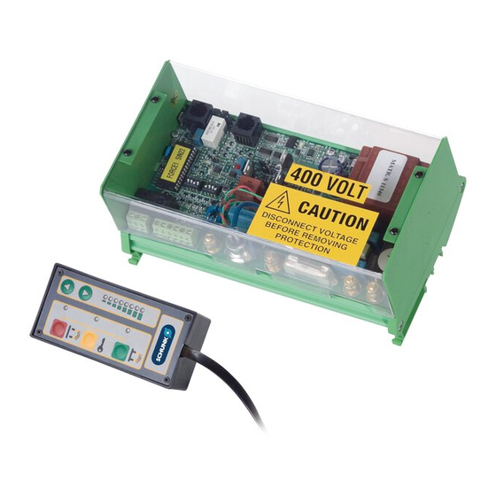
LED KEY Power adjustment push buttons KEY push button DEMAG push button DEMAG-LED Fig. 1 The scope of delivery includes: • Control unit • Remote control (supplied as standard on the KEH-P series, on request for all other types) QM.UC.00002-R3.0 |en... -
Page 10: Technical Data
Technical Data Technical Data Type FORCE-1.DIN / KEH.P / KEH.R Mains voltage 200 – 230 – 400 – 460 (VAC) Frequency 50Hz / 60Hz Phases 2 + PE Rated current 32 A Rated short circuit current 6 kA Breaking current of the fuse for 500 mA at 500 V AC the auxiliary cir-cuit IP rating... -
Page 11: Identification Plate
Phases Phases (mains) Current Rated current (mains) Rated short-circuit data Year Year of manufacture Weight Weight The identification plate must never be removed! Please always have the serial no. at hand when contacting SCHUNK about tech- nical matters. QM.UC.00002-R3.0 |en... -
Page 12: Dimensions
Technical Data Dimensions KEH-P01 FORCE-1.DIN FORCE-1.DIN.1C KEH.R01 KEH.R02 KEH.R03 Fig. 3 Dimensions FORCE-1.DIN and KEH.R KEH-P02 FORCE-1.DIN.2 FORCE-1.DIN.2C Fig. 4 Dimensions FORCE-1.DIN.2 QM.UC.00002-R3.0 |en... - Page 13 Technical Data KEH-P03-P08 FORCE-1.DIN.4 FORCE-1.DIN.3C FORCE-1.DIN.4C Fig. 5 Dimensions FORCE-1.DIN.3 and FORCE-1.DIN.4 FORCE-1.DIN.5, FORCE-1.DIN.6, FORCE-1.DIN.7 and FORCE-1.DIN.8 QM.UC.00002-R3.0 |en...
-
Page 14: Installation
Danger caused by short-circuit. Never start up the control unit if you have detected visual dam- age! • Notify the freight carrier or SCHUNK GmbH & Co. KG immedi- ately if you detect damage and/or missing components! (With all the relevant details.) 5 Compare the performance data on the identification plate of the control unit with the data of the electricity grid on site. - Page 15 Installation Position the control unit inside the electrical cabinet of the machine tool, making sure that the requirements of the IP protection class 5, Page 10) are met. We recommend installing the control unit and its power supply interrupting devices in an easily accessible place for maintenance and repairs, at a distance of approx.
-
Page 16: Initial Commissioning And Normal Operation
Initial commissioning and normal operation Initial commissioning and normal operation Initial commissioning After having installed the control unit 6, Page 14) as well as the electro-permanent magnetic chucks connected to the same, the following proper functioning must be checked: 1 Ensure that the magnetic chuck is not magnetized, by means of the steel tip of a screw driver. - Page 17 8 Remove the workpiece from the magnetic chuck. 9 Please contact SCHUNK if the expected results are not achieved even after having strictly followed the a.m. steps. PLEASE NOTE Please always have the serial no. at hand when contacting SCHUNK about technical matters! QM.UC.00002-R3.0 |en...
-
Page 18: Normal Operation
Initial commissioning and normal operation Normal operation To guarantee a proper functioning of the control unit, please carry out the following steps: 1 Ensure that the magnetic chuck is not magnetized, by means of the steel tip of a screw driver. 2 Apply voltage to the control unit. - Page 19 8 Make sure that the workpiece has been released from the magnetic chuck. 9 Remove the workpiece from the magnetic chuck. 10 Please contact SCHUNK if the expected results are not achieved even after having strictly followed the a.m. steps. NOTICE...
-
Page 20: Troubleshooting
The demagnetization cycle is Install a mains filter up- lar functioning of the control not carried out correctly stream to the control unit. unit. PLEASE NOTE Please always have the serial no. at hand when contacting SCHUNK about technical matters! QM.UC.00002-R3.0 |en... -
Page 21: Servicing And Maintenance
Maintenance work must always be performed by an electrician. The maintenance personnel must read this operating manual carefully. Work inside the control unit must be done by SCHUNK Service personnel only. This type of control unit has exclusively been designed to be in- stalled inside the electrical cabinet of the machine tool and doesn’t therefore require any specific maintenance. -
Page 22: Storage
Storage Storage When storing the control unit for a longer period of time (max. 8 months), observe the following instructions to ensure its function- ality up to the time of installation: • Ensure correct packaging! Recommendation: store the product in its original packaging. •... -
Page 23: Disposal
NOTE SCHUNK GmbH & Co. KG assumes no liability for material damage or personal injury that may result from reusing individual compo- nents of the control unit for purposes other than the original in- tended use! SCHUNK GmbH &... -
Page 24: Spare Parts
Spare parts Spare parts Please contact the SCHUNK service department for any spare parts request. QM.UC.00002-R3.0 |en...
Need help?
Do you have a question about the KEH-P and is the answer not in the manual?
Questions and answers