Table of Contents
Advertisement
Quick Links
Advertisement
Table of Contents

Related Manuals for SCHUNK LM Series


Summary of Contents for SCHUNK LM Series
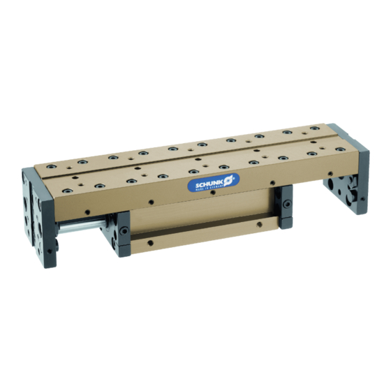
- Page 1 Translation of the original manual Assembly and operating manual Linear module...
- Page 2 Imprint Copyright: This manual is protected by copyright. The author is SCHUNK GmbH & Co. KG. All rights reserved. Any reproduction, processing, distribution (making available to third parties), translation or other usage - even excerpts - of the manual is especially prohibited and requires our written approval.
-
Page 3: Table Of Contents
Table of contents Table of contents General........................ 5 About this manual .................... 5 1.1.1 Presentation of Warning Labels ............... 5 1.1.2 Definition of Terms................... 6 1.1.3 Applicable documents ................ 6 1.1.4 Sizes ...................... 6 1.1.5 Variants..................... 6 Warranty ...................... 6 Scope of delivery .................... 6 Accessories ...................... - Page 4 Table of contents Assembly ........................ 17 Mechanical connection .................. 17 Air connection .................... 17 End position sets .................... 18 Setting the speed.................... 20 Adjustment of the shock absorber strocke ............ 21 Commissioning ....................... 22 Handling ......................... 23 Intermediate stops ZZA .................. 23 Intermediate stops LMZAW................ 24 Rod lock ......................
-
Page 5: General
General 1 General 1.1 About this manual This manual contains important information for a safe and appropriate use of the product. This manual is an integral part of the product and must be kept accessible for the personnel at all times. Before starting work, the personnel must have read and understood this operating manual. -
Page 6: Definition Of Terms
• Catalog data sheet of the purchased product * • Assembly and operating manuals of the accessories * The documents marked with an asterisk (*) can be downloaded on our homepage schunk.com 1.1.4 Sizes This operating manual applies to the following sizes: •... -
Page 7: Accessories
General 1.4 Accessories The following accessories are available for the module: • Adapter plate • Sensors • Intermediate stops • Rod lock • Stop screws 1.4.1 Sensors Overview of the compatible sensors Size Designation Type LM 25 - 50 Inductive proximity switches LM 100-300 Inductive proximity... -
Page 8: Stop Screw
General 1.4.4 Rod lock Die Absenksperre verhindert das Abfallen der Masse bei Energiev- erlust wie z.B. in Notaus-Situationen. Die Absenksperre kann auch nachträglich angebaut werden, jedoch verringert sich dadurch der Nutzhub. NOTICE Damage to the rod lock due to incorrect actuation / overload! The rod lock may only be triggered and unlocked when the •... -
Page 9: Basic Safety Notes
Use of unauthorized spare parts Using unauthorized spare parts can endanger personnel and damage the product or cause it to malfunction. • Use only original spare parts or spares authorized by SCHUNK. 04.00 | LM | Assembly and operating manual | en | 389291... -
Page 10: Environmental And Operating Conditions
• Ensure that no strong magnetic fields impair the function of the product. Contact your SCHUNK partner if the product is to be used in strong magnetic fields. 2.6 Personnel qualification Inadequate qualifications of the personnel... -
Page 11: Personal Protective Equipment
Basic safety notes 2.7 Personal protective equipment Use of personal protective equipment Personal protective equipment serves to protect staff against danger which may interfere with their health or safety at work. • When working on and with the product, observe the occupational health and safety regulations and wear the required personal protective equipment. -
Page 12: Transport
Basic safety notes 2.9 Transport Handling during transport Incorrect handling during transport may impair the product's safety and cause serious injuries and considerable material damage. • When handling heavy weights, use lifting equipment to lift the product and transport it by appropriate means. •... -
Page 13: Fundamental Dangers
Basic safety notes 2.12 Fundamental dangers General • Observe safety distances. • Never deactivate safety devices. • Before commissioning the product, take appropriate protective measures to secure the danger zone. • Disconnect power sources before installation, modification, maintenance, or calibration. Ensure that no residual energy remains in the system. -
Page 14: Protection Against Dangerous Movements
Basic safety notes 2.12.3 Protection against dangerous movements Unexpected movements Residual energy in the system may cause serious injuries while working with the product. • Switch off the energy supply, ensure that no residual energy re- mains and secure against inadvertent reactivation. •... -
Page 15: Information About Special Dangers
Basic safety notes 2.13 Information about special dangers WARNING Risk of injury caused by crushing and impacts when moving the unit or attachments! Risk of injury due to attachments breaking or becoming loose! WARNING Risk of injury from objects falling and being ejected! Falling and ejected objects during operation can lead to serious injury or death. -
Page 16: Technical Data
Technical data 3 Technical data Size Ambient temperature [°C] 5 - 60 Fluid consumption / 1.13 8.04 12.57 10 mm stroke IP rating Noise emission [dB(A)] Operating data for compressed Compressed air, air connection compressed air quality according to ISO 8573-1:7 4 4 Min. -
Page 17: Assembly
Assembly 4 Assembly 4.1 Mechanical connection The values relate to the entire bolting surface. Check the evenness of the bolting surface Requirements for levelness of the bolting surface Permissible unevenness [mm] < 0.02 The linear module may be selectively attached to the body or the Mounting carriage. -
Page 18: End Position Sets
Assembly Thread diameter of the air connections Designation Hose connection A = Extending G1/8" G1/8" linear module B =Retracting linear module 4.3 End position sets The following components are available for stroke limitation, damping and monitoring of end positions: • Stop screw LMAS-... Stop screw •... - Page 19 Assembly In order to adjust the linear module stroke, after undoing the Stroke adjustment clamping screw (5), the shock absorber stop LMST -... (7) and the proximity switch LMNS -... (6) can be adjusted together via a fine thread (not with KLM 25). The end position monitoring does not have to be readjusted.
-
Page 20: Setting The Speed
Assembly 4.4 Setting the speed NOTICE Risk of damage to the product! If the end position is approached too hard, the product may be damaged. Adjust exhaust throttle valve and shock absorber so that the • movement is braked smoothly. Close exhaust throttle valve completely. -
Page 21: Adjustment Of The Shock Absorber Strocke
Assembly 4.5 Adjustment of the shock absorber strocke Movement End position Damping Time T Target time The shock absorber stroke is too long and the end position is reached too slowly. Movement End position Damping Time T Target time The shock absorber stroke is too short and the unit arrives in the end position too abruptly. -
Page 22: Commissioning
Commissioning 5 Commissioning NOTICE Before commissioning! Please read these instructions carefully. Only with the knowledge of this manual errors can be prevented, and trouble-free operation is ensured. • Check technical specifications Technical data 16]. • Do not use the linear module until you have determined that it is in perfect operating condition, after having checked for compliance with all permissible operating parameters. -
Page 23: Handling
Handling 6 Handling 6.1 Intermediate stops ZZA NOTICE Note the General Notes toHandling 23] Intermediate stops are add-on modules for linear modules. 2 models are available for all LM linear modules: • Execution 1: Attachment LM piston-side • Execution 2: Attachment LM rod-side Intermediate stops execution 1 Execution 1 is shown. -
Page 24: Intermediate Stops Lmzaw
Handling 6.2 Intermediate stops LMZAW LMZAW Intermediate stops are additional modules for linear actuators of series LM 100, LM 200 and LM 300. They can be mounted on either the piston side or rod side of the linear actuator. Intermediate stops LMZAW - mounting on the piston side LM 100 - STD 1203 LM 100/200/300 - NI 30 LM 200/300 - STD 1403... - Page 25 Handling Attachment piston sided Permitted movements: Diagrams (1) / (2) and table horizontal vertical Homing of linear actuator (LMZAW) Stroke motion Pos. 1 → Pos. 3 Pos. 3 → Pos. 1 Pos. 1 → Pos. 2 Pos. 2 → Pos. 1 Pos.
- Page 26 Handling Attachment rod sided Permitted movements: Diagrams (1) / (2) and table horizontal vertical Homing of linear actuator (LMZAW) Stroke motion Pos. 1 → Pos. 3 Pos. 3 → Pos. 1 Pos. 1 → Pos. 2 Pos. 2 → Pos. 1 04.00 | LM | Assembly and operating manual | en | 389291...
-
Page 27: Rod Lock
Handling 6.3 Rod lock NOTICE Damage to the rod lock due to incorrect actuation / overload! The rod lock may only be triggered and unlocked when the • product has been shut down. See the data on static holding force in the catalog. The forces •... - Page 28 Handling 1. Remove face plate I (C) and cover plate I (B). Assembly of ASP rod lock 2. Install the completely installed rod lock (A) on the module. Grease wiper ring! Maintenance and care The cover plate (B) is no longer required. 3.
-
Page 29: Troubleshooting
Troubleshooting 7 Troubleshooting 7.1 Module does not move Possible cause Corrective action Pressure drops below minimum. Check air supply. Link Luftanschlüsse Compressed air lines switched. Check compressed air lines. Link Luftanschlüsse 7.2 End position signal not present Possible cause Corrective action Proximity switch defective or set incorrect. -
Page 30: Maintenance And Care
Maintenance and care 8 Maintenance and care Activity Maintenance intervals Functional test damper regularly Change of shock absorber 2 Mio. cycles Check Condition of the seals regularly Change the seals If necessary Lubricate the guides every 3.000 km Grease Isoflex-Topas NCA 52 or equivalent 04.00 | LM | Assembly and operating manual | en | 389291... -
Page 31: Translation Of Original Declaration Of Incorporation
9 Translation of original declaration of incorporation in terms of the Directive 2006/42/EG, Annex II, Part 1.B of the European Parliament and of the Council on machinery. Manufacturer/ SCHUNK GmbH & Co. KG Spann- und Greiftechnik Distributor Bahnhofstr. 106 – 134 D-74348 Lauffen/Neckar... -
Page 32: Annex To Declaration Of Incorporation
Annex to Declaration of Incorporation 10 Annex to Declaration of Incorporation according 2006/42/EG, Annex II, No. 1 B 1.Description of the essential health and safety requirements pursuant to 2006/42/EC, Annex I that are applicable and that have been fulfilled with: Product designation Linear module Type designation ID number... - Page 33 Annex to Declaration of Incorporation Protection against mechanical hazards 1.3.1 Risk of loss of stability 1.3.2 Risk of break-up during operation 1.3.3 Risks due to falling or ejected objects 1.3.4 Risks due to surfaces, edges or angles 1.3.5 Risks related to combined machinery 1.3.6 Risks related to variations in operating conditions 1.3.7...
- Page 34 Annex to Declaration of Incorporation Maintenance 1.6.1 Machinery maintenance 1.6.2 Access to operating positions and servicing points 1.6.3 Isolation of energy sources 1.6.4 Operator intervention 1.6.5 Cleaning of internal parts Information 1.7.1 Information and warnings on the machinery 1.7.1.1 Information and information devices 1.7.1.2 Warning devices 1.7.2...
- Page 35 Notes Notes 04.00 | LM | Assembly and operating manual | en | 389291...
- Page 36 04.00 | LM | Assembly and operating manual | en | 389291...
Need help?
Do you have a question about the LM Series and is the answer not in the manual?
Questions and answers