
Related Manuals for SCHUNK DL9-T PROFINET


Summary of Contents for SCHUNK DL9-T PROFINET
- Page 1 Original manual Control and Signal Module DL9-M and DL9-T PROFINET Assembly and Operating manual Superior Clamping and Gripping...
- Page 2 Imprint Copyright: This manual is protected by copyright. The author is SCHUNK GmbH & Co. KG. All rights reserved. Any reproduction, processing, distribution (making available to third parties), translation or other usage - even excerpts - of the manual is especially prohibited and re- quires our written approval.
-
Page 3: Table Of Contents
5.3 DL9 Device Replacement Procedures ..............47 5.3.1 Replace DL9 module with a new “out-of-the-box” DL9 module ....47 5.3.2 Replace DL9 module with an already-commissioned DL9 module .... 48 6 Trouble shooting ..................... 50 7 Recommended Spare Parts ..................52 02.00|DL9-M and DL9-T PROFINET |en... - Page 4 Table of contents 8 Specifications ......................53 9 Drawings ......................... 55 02.00|DL9-M and DL9-T PROFINET |en...
-
Page 5: Glossary
A proximity sensor input indicating that the coupling mechanism is in the Locked position. Output Power Available An input indicating the presence of Output Power (US2) at the ATI master module. Power Sense An input indicating the presence of Input and Logic 02.00|DL9-M and DL9-T PROFINET |en... - Page 6 A virtual input used to describe the behavior of the master module firmware in regards to allowing an Un- latch output to be processed. Unlocked A proximity sensor input indicating that the coupling mechanism is in the Unlocked position. 02.00|DL9-M and DL9-T PROFINET |en...
- Page 7 US1 Power Good An input indicating the presence of Input and Logic Power (US1) at the ATI master module. V1Relay and V2Relay Inputs from relays which should mirror the status of SSO1 and SSO2. 02.00|DL9-M and DL9-T PROFINET |en...
-
Page 8: Description
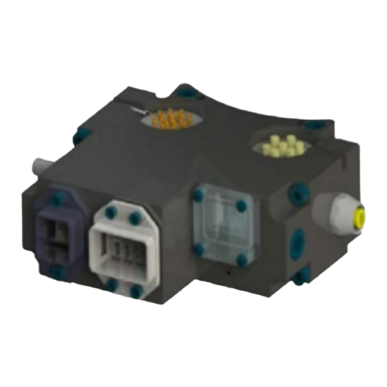
Master and Tool modules pass signals via a spring-loaded pin block. A flexible boot surrounds the pin block to seal the connec- tion from moisture and liquid while coupled, see figure "DL9 PROFINET Master and Tool Modules". 02.00|DL9-M and DL9-T PROFINET |en... -
Page 9: Master Module And Tool Module
Refer to ( 3.2, Page 27) for additional in- formation regarding the Arc Prevention Circuit. 02.00|DL9-M and DL9-T PROFINET |en... - Page 10 The Tool-ID is reported through the Master module bitmap. See ( 3.1.1, Page 19) for PROFINET bitmap and detailed I/O information. A M12 5-pin connector provides connec- tion to the non-contact safety switch that is integrated into the safety circuit. 02.00|DL9-M and DL9-T PROFINET |en...
-
Page 11: Installation
Tool Changer or modules. The control/signal modules are typically installed by SCHUNK prior to shipment. The steps below outline the field installation or re- moval as required. The DL9 Master Module is mounted to the JR4- M valve adapter module on flat A of the Tool Changers Master Plate. - Page 12 The DL9 Master Modules has four M8 3-Pin female connectors for RTL1, RTL2, Locked, and Unlocked connections. The Master mod- ule has two connectors to interface with the valve adaptor, an M8 3-Pin female connector to interface with the Proximity sensor and 02.00|DL9-M and DL9-T PROFINET |en...
- Page 13 A M12 5-Pin connector on the Tool module is used to connect the Euchner Safety Switch. M8 3-Pin female connectors for RTL1, RTL2, Locked, and Unlocked Signal US1+ US1- Input M8 3-Pin Female Valve Adapter Proximity Sensor Signal US1+ US1- Input 02.00|DL9-M and DL9-T PROFINET |en...
- Page 14 SSO2 SSFAULT The Latch and Unlatch signals to the JR4 Valve Adapter are trans- mitted through a 4-Pin internal pin block to prevent damage or other environmental factors that could cause the signals to short. 02.00|DL9-M and DL9-T PROFINET |en...
- Page 15 Installation Pin Internal Pin Block Signal Latch Unlatch2 Unlatch1 02.00|DL9-M and DL9-T PROFINET |en...
-
Page 16: Installing Dl9-M Control/Signal Module
DL9-M Module. 5 Connect the Euchner Safety switch cable to the connector on the DL9-M Module. 6 Connect the RTL1, RTL2, Lock, and Unlock sensor cables to the connectors on the DL9-M Module. 02.00|DL9-M and DL9-T PROFINET |en... -
Page 17: Remove The Dl9-M Control/Signal Module
Spacer Module prior to installing the module in order to re- move any debris that may be present. 2 Using the ledge feature as a guide place the DL9-T Con- trol/Signal Module on the JR4 Spacer Module mounting sur- 02.00|DL9-M and DL9-T PROFINET |en... -
Page 18: Remove The Dl9-T Control/Signal Module
Tool Changer. A detailed operational sequence is provided in chapter ( 4.3, Page 41). Utility Schematic Refer to ( 9, Page 55) of this manual for customer interface and wiring details for the DL9-M/DL9-T modules. 02.00|DL9-M and DL9-T PROFINET |en... -
Page 19: Product Information
DL9-M Node GSDML file Robot input and output bitmaps for the Master node are provided in the follwing tabeles "I/O Bitmap, Robot Inputs from SWO-L-DL9-K Module" and "I/O Bitmap, Robot Outputs to SWO-L-DL9-K Module". 02.00|DL9-M and DL9-T PROFINET |en... - Page 20 & unlock sensors or bad sensors or no latch/unlatch motion. TOOL-ID_ERROR Tool ID Communication Timeout UNSAFE_LATCH User attempted to latch when unsafe. Reset at next rising edge of latch command. SYSTEM_IS_UNSAFE Any APx_COMM_ERROR, 02.00|DL9-M and DL9-T PROFINET |en...
- Page 21 Pressure sensor reports an unlatch pressure higher than the maximum system rating. Reset with “clear errors” output bit or with next un- latch command that progresses to turning on UNLATCH_VALVE_CTRL1 (in order to supply air to the pressure sensor). 02.00|DL9-M and DL9-T PROFINET |en...
- Page 22 Major Revision Bit3 uC firmware revision (Reserved) (Reserved) 1 to (Reserved) PRESSURE_ Internal bit indicating that the pressure sensor is SENSOR_ disconnected and/or that there are broken wires DISCONNECTED in the sensor cable 6 to (Reserved) (Reserved) 02.00|DL9-M and DL9-T PROFINET |en...
-
Page 23: Integrated Ethernet Switch
The DL9 Master Module provides an integrated 2-port Ethernet switch which supports the following: • Transmission rate 100 MBit/s • Interface type 100 BASE-TX, isolated • Half duplex/Full duplex supported . • Auto-Negotiation supported • Auto-Crossover supported 02.00|DL9-M and DL9-T PROFINET |en... -
Page 24: System Failure And Bus Failure Leds
LED’s operation. The Bus Failure (BF) status LED is identified on the module as “BF”. It provides PROFINET status information. Refer to the following ta- ble for an outline of this LED’s operation. 02.00|DL9-M and DL9-T PROFINET |en... - Page 25 SF LED Note Off Line Device not on line. Device may not have an IP address or may be powered off. Operational Green Normal operation Not OK No configuration Not OK Red blinking No data exchange. 02.00|DL9-M and DL9-T PROFINET |en...
-
Page 26: Ethernet 1 And Ethernet 2 Leds
Tool module but there is currently no data exchange activity. Active RX/TX Blinking Amber There is sporadic data exchange activity with the Ethernet. PROFINET Amber There is continuous data exchange activity with the Ether- connection net. established 02.00|DL9-M and DL9-T PROFINET |en... -
Page 27: Reset-To-Factory Push-Button
Make sure to re-apply the LED window cover after access to the push-button is not needed anymore. Arc Prevention Circuit The DL9 Module incorporates SCHUNK’s exclusive Arc Prevention Circuit. The Arc Prevention Circuit extends the life of all electrical power contacts by eliminating arcing caused by inductive loads and high inrush current during coupling/uncoupling. -
Page 28: Arc Prevention Circuit Behavior During Coupling
100ms. Important: The Arc Prevention Circuit will only allow power to pass to the Tool after the LATCH command has been issued and the Master and Tool module’s electrical contacts are fully engaged. Power-On Timing 02.00|DL9-M and DL9-T PROFINET |en... - Page 29 High current spikes can cause voltage drops on the power supply and potentially may lead to network faults. The Arc Prevention Cir- cuit has an SCHUNK exclusive Soft Start feature that pulses the power on gradually in the beginning, preventing the large current spike that would otherwise occur if there were only one hard on signal.
-
Page 30: Arc Prevention Circuit Behavior During Uncoupling
EOAT, the friction between Master and Tool alignment pins, etc. but is usually not shorter than 100ms. Arc Prevention Circuit Power-Off Timing 02.00|DL9-M and DL9-T PROFINET |en... -
Page 31: Tool Module
Master and Tool are coupled and the Tool ID fails to be report- ed, a Tool-ID_Error shall be set. DL9 Tool Module, Tool-ID Switch Settings For details of how the Tool-ID is reported: ( 3.1.1, Page 19) 02.00|DL9-M and DL9-T PROFINET |en... -
Page 32: Safety System
Application Processors. The JR4/JU4 Valve Adapt- er is equipped with two double-solenoid valves. Pressure and proximity sensor outputs provided by the Valve Adapter are evalu- ated by the Application Processors for diagnostic purposes. 02.00|DL9-M and DL9-T PROFINET |en... - Page 33 The safety switch is connected to the DL9 Mas- ter Module by a five conductor M12 cable. Refer to the JR4/JU4 Valve adapter manual for detailed information on the dual double solenoid valve functionality. 02.00|DL9-M and DL9-T PROFINET |en...
- Page 34 Euchner CES-AP with the DL9 module. Use of unapproved switches will void the PL d safety rating. • Contact SCHUNK before using another safety rated switch. Safety Switch (Modules Shown for Reference Only) 02.00|DL9-M and DL9-T PROFINET |en...
-
Page 35: Operation
The following information is provided to help define the be- havior of the DL9-M/DL9-T modules. Inputs The following describes the most critical inputs from the SCHUNK Master module. Locked A proximity sensor input indicating that the coupling mechanism is in the Lock position. - Page 36 • Air pressure within operating range • UNLOCKED bit is 0 • LATCH bit is 0 • The Tool is in the tool stand as indicated by SSO1, SSO2, V1RELAY, and V2RELAY bits being 1 02.00|DL9-M and DL9-T PROFINET |en...
-
Page 37: Error Conditions
PRES- SURE_TOO_LOW bit will be set. The error can be reset with the “Clear Errors” bit or by supplying air at the correct pressure. 02.00|DL9-M and DL9-T PROFINET |en... - Page 38 This error bit will be reset when a new UN- LATCH command is received (UNLATCH command removed and reapplied) and the UNLATCH_ENABLE conditions are met or with the rising edge of the “Clear Errors” output bit. 02.00|DL9-M and DL9-T PROFINET |en...
- Page 39 UNLATCH output to Valve Unlatch) LOCK/UNLOCK Sen- LOCKED and UNLOCKED No (Yes only during Correct error or sor Fault Sensor on at the same Unlatch) Clear Errors Bit time PRES- Pressure Sensor not Clear Errors Bit 02.00|DL9-M and DL9-T PROFINET |en...
- Page 40 Rising edge of unsafe conditions LATCH or Clear Er- rors Bit UNSAFE_UNLATCH Unlatch requested under Rising edge of UN- unsafe conditions LATCH or Clear Er- rors Bit VALVE_ERROR Valve module pressure Clear Errors Bit and/or position error 02.00|DL9-M and DL9-T PROFINET |en...
-
Page 41: Recommended Sequence Of Operation
The Unlocked inputs are 1. c. The Locked inputs are 0. d. The SSO_1, SSO_2, V1RELAY, and V2RELAY inputs are 0. e. The SCHUNK tool and any downstream PROFINET device(s) are offline. The US1_Power_Present (Input Power) and US2_Power_Present (output Power) inputs are true and must remain so at all times. - Page 42 The following inputs are off: Unlocked II. SSO_1 III. SSO_2 IV. V1RELAY V. V2RELAY VI. Unlatch Enabled b. The following inputs are on: Locked II. US1 Power (Input Power) III. US2 Power (Output Power) IV. RTL1 and RTL2 02.00|DL9-M and DL9-T PROFINET |en...
- Page 43 0.06” to 0.15” of the tool. a. The Safety Switch becomes deactivated, and the SSO_1, SSO_2, V1RELAY, and V2RELAY inputs go off. b. Unlatch Enabled is off. c. Everything is OK bit is on.) 02.00|DL9-M and DL9-T PROFINET |en...
- Page 44 Unlocked II. US1 Power (Input Power) III. US2 Power (Output Power) IV. Everything is OK V. Tool-ID invalid (all 1→ 0xFFFF) c. The following outputs are off: Latch d. The following outputs are on: Unlatch 02.00|DL9-M and DL9-T PROFINET |en...
-
Page 45: Maintenance And Care
3 Inspect the Master and Tool pin blocks for any pin damage, debris or darkened pins. Refer to ( 5.1, Page 46). 4 Inspect V-Ring seals for wear, abrasion, and cuts. If worn or damaged, replace. Refer to ( 5.2, Page 47). 02.00|DL9-M and DL9-T PROFINET |en... -
Page 46: Pin Block Inspection And Cleaning
• Clean contact surfaces with a vacuum or non-abrasive media such as a nylon brush. 3 Inspect the Master and Tool pin blocks for stuck pins or severe pin block damage. Stuck Pin and Pin Block Damage 02.00|DL9-M and DL9-T PROFINET |en... -
Page 47: Seal Replacement
Maintenance and care 4 If stuck pins or severe pin block damage exists, contact SCHUNK for possible pin replacement procedures or module replacement. Seal Replacement Replace the V-Ring seal: 1 To remove the existing seal, pinch edge of seal with fingers and gently pull the seal away from the pin block on the Mas- ter. -
Page 48: Replace Dl9 Module With An Already-Commissioned Dl9 Module
DL9-M Module. 8 Connect the 5-Pin Power cable to the connectors on the DL9- M Module. Module Installation and Removal DL9-M Control/Signal Module 9 Loosen two M3 Pan Head Captive Screws and remove LED window. 02.00|DL9-M and DL9-T PROFINET |en... - Page 49 15 The “new” module will automatically get the name and IP ad- dress of the old module assigned. 16 After a few seconds it should be operating on the network. 17 The SF LED should be GREEN. 02.00|DL9-M and DL9-T PROFINET |en...
-
Page 50: Trouble Shooting
Ensure that the Tool Plate is securely held to ating correctly) the Master Plate and that nothing is trapped between their surfaces, and that there is no air trapped in the Unlock (U) air port. 02.00|DL9-M and DL9-T PROFINET |en... - Page 51 Power on the Tool- will cause loss of US2 (Auxiliary) power to the side Tool. The Arc Prevention Circuit relies on US1 power to operate. Restore US1 power to the Master to restore US2 power to the Tool. 02.00|DL9-M and DL9-T PROFINET |en...
-
Page 52: Recommended Spare Parts
Recommended Spare Parts Recommended Spare Parts Description Part Number SWO-L-DL9-K 1320479 SWO-L-DL9-A 1320480 ( 9, Page 55) for spare parts directly associated with the DL9-M/DL9-T modules. 01.00|DL9-M and DL9-T PROFINET |en... -
Page 53: Specifications
(only when Locking or Unlocking Tool Changer). Note: Power source for US1 and US2 Power must be a 24 VDC certified power supply or equivalent voltage controlled power supply and must be protected by a user installed external 10 A fuse. 02.00|DL9-M and DL9-T PROFINET |en... - Page 54 *Current Draw US1 Power: 220 mA @ 24 VDC: Master and Tool with Locked, RTL1, and RTL2 sensors “on” and Safety Switch activating V1 and V2 Relays. Enclosure IP65 Temperature 0 to 49 °C Weight 0.84 kg 02.00|DL9-M and DL9-T PROFINET |en...
- Page 55 Drawings Drawings 02.00|DL9-M and DL9-T PROFINET |en...
- Page 56 Drawings 02.00|DL9-M and DL9-T PROFINET |en...
- Page 57 Drawings 02.00|DL9-M and DL9-T PROFINET |en...
- Page 58 Drawings 02.00|DL9-M and DL9-T PROFINET |en...
- Page 59 Drawings 02.00|DL9-M and DL9-T PROFINET |en...
- Page 60 Drawings 02.00|DL9-M and DL9-T PROFINET |en...
Need help?
Do you have a question about the DL9-T PROFINET and is the answer not in the manual?
Questions and answers