
Subscribe to Our Youtube Channel
Related Manuals for SCHUNK ELP Series


Summary of Contents for SCHUNK ELP Series
- Page 1 Translation of the original manual Assembly and operating manual Electrical Linear Module Firmeware 5-1.1.0...
- Page 2 Imprint Copyright: This manual is protected by copyright. The author is SCHUNK GmbH & Co. KG. All rights reserved. Any reproduction, processing, distribution (making available to third parties), translation or other usage - even excerpts - of the manual is especially prohibited and requires our written approval.
-
Page 3: Table Of Contents
Table of Contents Table of Contents General........................ 5 About this manual .................... 5 1.1.1 Presentation of Warning Labels ............... 5 1.1.2 Definition of Terms................... 5 1.1.3 Applicable documents ................ 6 1.1.4 Sizes ...................... 6 1.1.5 Variants..................... 6 1.1.6 Firmware.................... 6 Warranty ...................... 6 Scope of delivery .................... 7 1.3.1 Accessory pack.................. 7 Accessories ...................... - Page 4 Table of Contents 4.3.1 Power supply .................. 22 Safety function STO (Safe Torque Off).............. 25 4.4.1 Examples of actuation in the event of an emergency stop .... 25 Displays and control elements ................ 27 4.5.1 Rotary switch .................. 27 4.5.2 Displays in the "Auto-Learn" operating mode........ 28 4.5.3 Displays in the "M1"...
-
Page 5: General
General 1 General 1.1 About this manual This manual contains important information for a safe and appropriate use of the product. This manual is an integral part of the product and must be kept accessible for the personnel at all times. Before starting work, the personnel must have read and understood this operating manual. -
Page 6: Applicable Documents
• Catalog data sheet of the purchased product * • Assembly and operating manuals of the accessories * The documents marked with an asterisk (*) can be downloaded on our homepage schunk.com 1.1.4 Sizes This operating manual applies to the following sizes: •... -
Page 7: Scope Of Delivery
General 1.3 Scope of delivery The scope of delivery includes • Electric linear module ELP in the version ordered • Assembly and Operating Manual • Accessory pack 1.3.1 Accessory pack Content of the accessory pack: Accessory pack Contents ELP 025 Centering sleeves: 4 x ZHU 8 ELP 050 Centering sleeves: 4 x ZHU 8 + 4 x ZHU 10... -
Page 8: Basic Safety Notes
Use of unauthorized spare parts Using unauthorized spare parts can endanger personnel and damage the product or cause it to malfunction. • Use only original spare parts or spares authorized by SCHUNK. 07.00 | ELP | Assembly and operating manual | en | GAS406217/1432399... -
Page 9: Ambient Conditions And Operating Conditions
Basic safety notes 2.5 Ambient conditions and operating conditions Required ambient conditions and operating conditions Incorrect ambient and operating conditions can make the product unsafe, leading to the risk of serious injuries, considerable material damage and/or a significant reduction to the product's life span. •... -
Page 10: Personal Protective Equipment
Basic safety notes 2.7 Personal protective equipment Use of personal protective equipment Personal protective equipment serves to protect staff against danger which may interfere with their health or safety at work. • When working on and with the product, observe the occupational health and safety regulations and wear the required personal protective equipment. -
Page 11: Malfunctions
Basic safety notes 2.10 Malfunctions Behavior in case of malfunctions • Immediately remove the product from operation and report the malfunction to the responsible departments/persons. • Order appropriately trained personnel to rectify the malfunction. • Do not recommission the product until the malfunction has been rectified. -
Page 12: Protection During Handling And Assembly
Basic safety notes 2.12.1 Protection during handling and assembly Incorrect handling and assembly Incorrect handling and assembly may impair the product's safety and cause serious injuries and considerable material damage. • Have all work carried out by appropriately qualified personnel. •... -
Page 13: Protection Against Dangerous Movements
Basic safety notes 2.12.3 Protection against dangerous movements Unexpected movements Residual energy in the system may cause serious injuries while working with the product. • Switch off the energy supply, ensure that no residual energy remains and secure against inadvertent reactivation. •... -
Page 14: Protection Against Magnetic And Electromagnetic Fields
Basic safety notes 2.12.5 Protection against magnetic and electromagnetic fields Work in areas with magnetic and electromagnetic fields Magnetic and electromagnetic fields can lead to serious injuries. • Persons with pace-makers, metal implants, metal shards, or hearing aids require the consent of a physician before entering areas in which components of the electric drive and control systems are mounted, started up, and operated. -
Page 15: Notes On Particular Risks
Basic safety notes 2.13 Notes on particular risks DANGER Risk of injury due to magnetic fields! The integrated electric permanent magnets can pose a risk to people with an active or passive implant. People with pacemakers or active or passive implants are •... -
Page 16: Technical Data
Technical data 3 Technical data 3.1 Basic data Types ELP 025- ELP 025- ELP 025- H030 H050 H080 ID number 0315700 0315708 0315716 Stroke [mm] min. / max. 5 / 30 20 / 50 50 / 80 Stroke adjustment range per side [mm] Logic voltage and actuator voltage [V] +/- 10% Rated current (Logic) [A] 0.04... - Page 17 Technical data Types ELP 050- ELP 050- ELP 050- H040 H060 H100 ID number 0315724 0315732 0315740 Stroke [mm] min. / max. 5 / 40 20 / 60 60 / 100 Stroke adjustment range per side [mm] Logic voltage and actuator voltage [V] +/- 10% Rated current (Logic) [A] 0.04 0.04...
- Page 18 Technical data Types ELP 100- ELP 100- ELP 100- H080 H120 H200 ID number 0315748 0315756 0315764 Stroke [mm] min. / max. 30 / 80 70 / 120 150 / 200 Stroke adjustment range per side [mm] Logic voltage and actuator voltage [V] +/- 10% Rated current (Logic) [A] 0.06 0.06...
-
Page 19: Ambient Conditions And Operating Conditions
* For use in dirty ambient conditions (e.g. sprayed water, vapors, abrasion or processing dust) SCHUNK offers corresponding product options as standard. SCHUNK also offers customized solutions for special applications in dirty ambient conditions. 07.00 | ELP | Assembly and operating manual | en | GAS406217/1432399... -
Page 20: Design And Description
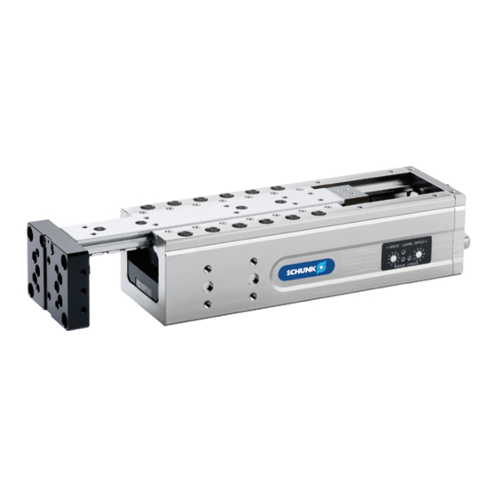
Design and description 4 Design and description 4.1 Configuration Electric linear module ELP Flange plate for securing the customer application Product fastening (top) Slides for securing the customer application Operating field Product fastening (side) Accessories fastening Grooves for sensors (2 pieces) Product fastening (bottom) Name plate M8 plug for digital signals... -
Page 21: Name Plate
= 24 V; = 1.6 A; = 104 N; 2020.01.10_11:41; schunk.com/elp NOTE If the product has a firmware version older than 5-1.1.0, the firmware version is not included in the string. 07.00 | ELP | Assembly and operating manual | en | GAS406217/1432399... -
Page 22: Description
Design and description 4.3 Description Electrical linear module with a directly driven 3-phase synchronous motor, which produces linear movements or forces • no mechanical power transmission elements (direct drive) • electrical drive controllers integrated • Actuation via digital signals • Cycle times adjustable via rotary switch •... - Page 23 0V terminals, which are connected to the protective conductor PE using a separation terminal. Only use the distributor recommended by SCHUNK as an accessory with separate return lines. For the supply, power supply units with secure disconnection in accordance with IEC 60364-4-41 (DIN VDE 0100-410) must be used.
- Page 24 Design and description -TB1 power supply unit control/sensor system 24 V -TB2 power supply unit actuators 24 V energy-recovery capable -Retract KF1 EL -Extend KF2 ELP -RA1 brake chopper Wiring principle, correct -TB1 power supply unit 24 V -Retract KF1 EL - Extend KF2 ELP -RA1 brake chopper Wiring principle, incorrect 07.00 | ELP | Assembly and operating manual | en | GAS406217/1432399...
-
Page 25: Safety Function Sto (Safe Torque Off)
Design and description 4.4 Safety function STO (Safe Torque Off) The product does not have an input for STO. The "Power off" operating state is not a safety function and may not be used for STO. However, there is the possibility of a monitored shut-down of the actuator voltage Ua and logic voltage Us at the customer site using a safety switch. - Page 26 Design and description Example 2: Switching off the actuator voltage This example serves as a possible template for switching off the actuator power supply in case of an emergency stop. The logic voltage is not switched off. Operator triggers emergency stop signal. Ø...
-
Page 27: Displays And Control Elements
Design and description 4.5 Displays and control elements Operating field Rotary switch stroke time when extending Displays the travel direction for rotary switch (1) LED diagnostics: Learn Displays the travel direction for the rotary switch (5) Rotary switch stroke time when retracting LED diagnostics: Power LED diagnostics: Error 4.5.1 Rotary switch... -
Page 28: Displays In The "Auto-Learn" Operating Mode
Design and description 4.5.2 Displays in the "Auto-Learn" operating mode Color Status Meaning Power Green Ready for operation Logic voltage or actuator voltage are incorrectly poled or not in the valid range Learn Yellow The product has a previous stroke taught in Normal Operation Error The product has detected a... -
Page 29: Operating Mode
Design and description 4.6 Operating mode 4.6.1 "Auto-Learn" operating mode Description Using the auto-learn function, the product can be commissioned easily. This function takes into account the conditions such as – horizontal or vertical setup, – fitted payload, end stop setting, –... -
Page 30: Operating Mode "M1
Design and description 4.6.2 Operating mode "M1" Description In the operating mode "M1", the motion profile of the product can be adjusted manually. The length of the acceleration and braking phase is set directly via the rotary switch. The maximum adjustable level is limited by overall stroke, payload and position. -
Page 31: Actuation
Design and description 4.7 Actuation Truth table The truth table shows the actuation of the digital inputs during possible commands by the superordinated control unit. The signals at the digital inputs may be switched simultaneously. On detecting a signal change, the product switches to the new status after the activation time has elapsed. - Page 32 Design and description Examples for activation time • Between the commands "retract" and "extend", an undesired time of 15 ms arises in the PLC actuation, during which time both signals at Pin 2 and Pin 4 are on "0". Here, the last motion command is not interrupted by a "Power off"...
-
Page 33: Assembly And Settings
Assembly and settings 5 Assembly and settings 5.1 Assembly and connection WARNING Risk of injury due to sudden movements! Is the energy supply is switched on, this can cause components to move unexpectedly, which may result in serious injuries. Disconnect power sources before installation and calibration. •... -
Page 34: Connections
< 0.02 > 100 < 0.05 The product can be mounted from three sides. When selecting the fastening screws, observe the values prescribed by SCHUNK, see following table. Assembly options Item Mounting ELP 025 ELP 050 ELP 100 Product from above... - Page 35 Assembly and settings 5.2.1.2 Assembly possibilities for customer applications The customer application can be secured on the flange plate from the front, at the back and on the slide. Securing on the flange plate from the front Assembly possibility for customer applications (flange plate from the front) Item Mounting ELP 025 ELP 050 ELP 100...
- Page 36 Assembly and settings Securing on the flange plate from the back and on the slide Assembly possibility for customer applications (flange plate from the back, on the slide) Item Mounting ELP 025 ELP 050 ELP 100 Slide top Screws Drilling pattern 15 x 45 20 x 60 [mm x mm]...
- Page 37 Machine flange [mm] 5.2.1.4 Tightening torques Screw dimension Tightening torque [Nm] for strength class 8.8 * * SCHUNK recommends screws with a strength class of 8.8 and above. 5.2.1.5 Dimensions of the centering elements Designation Ø W x H x L ID no.
-
Page 38: Electrical Connection
Assembly and settings 5.2.2 Electrical connection Pin allocation A: Connection for actuation 4-pole M8 connector (view on the connector) B: Connection for power supply 4-pole M12 connector, T coded (view on the connector) A: Actuation Wire color (*) Signal brown not connected white Retract... -
Page 39: Adjust End Position
Assembly and settings 5.3 Adjust end position Loosen clamping element with Allen key (1). Ø Put end position into the desired position using the Allen key Ø (2). (Thread pitch 1 mm) Retighten clamping element. Ø For tightening torque, see following table: Item Designation ELP 025 ELP 050 ELP 100... -
Page 40: Mounting The Sensor
– The assembly and operating manual and catalog datasheet are included in the scope of delivery for the sensors and are available at schunk.com. • Information on handling sensors is available at schunk.com or from SCHUNK contact persons. 5.4.1 Overview of sensors... -
Page 41: Mounting Mms 22 Magnetic Switch
Assembly and settings 5.4.2 Mounting MMS 22 magnetic switch CAUTION Risk of damage to the sensor during assembly! Observe the maximal tightening torque. • Set "slide extended" position End position is set, Adjust end position 39]. ■ Extend slide to end position. Ø... -
Page 42: Mounting Inductive Proximity Switch In 80
Assembly and settings 5.4.3 Mounting inductive proximity switch IN 80 CAUTION Risk of damage to the sensor during assembly! Observe the maximal tightening torque. • Item Screw dimension Maximum tightening torque [Nm] M3 x 8, DIN 7991 M3 x 12, DIN EN ISO 4762 0.4 M3 x 12, DIN EN ISO 4762 0.4 Installing switching lug ELP 025: Secure switching lug (1) with two screws (2) on the slides. - Page 43 Assembly and settings Set "slide extended" position End position is set, Adjust end position 39]. ■ Extend slide to end position. Ø Secure T-nut (10) to the bracket (11) with two screws (12). Ø Tighten screws only slightly. Slide T-nut (10) with attached bracket (11) into the groove (4), Ø...
-
Page 44: Assemble Additional Accessories
Assembly and settings 5.5 Assemble additional accessories 5.5.1 Assemble load compensation (MagSpring ®) Item Screw dimension M4 x 16, DIN EN ISO 4762 M4 x 16, DIN EN ISO 4762 M4 x 20, DIN EN ISO 4762 M4 x 30, DIN EN ISO 4762 M5 x 16, DIN EN ISO 4762 NOTE Secure all screw connections with the thrust washer provided. - Page 45 Assembly and settings Insert runs (10) into the stator (12), refer to "MagSpring®" Ø operating manual for this. Fasten clamping element (1) to housing using two screws (2). Ø Only tighten screws lightly, so that the clamping element (1) cannot move. Secure angular compensation (8) on the mounting plate (5) Ø...
-
Page 46: Mount Strain Relieve For Cable
Assembly and settings 5.5.2 Mount strain relieve for cable Item Screw dimension ELP 025 ELP 050 ELP 100 M5 x 10, DIN 7380 M6 x 10, DIN 7380 M8 x 10, DIN 7380 M4 x 10, DIN 7991 Secure retaining plate (1) with two screws (2) on the housing Ø... -
Page 47: Installing Electric Lowering Lock
M5 x 12 / 5.1 Nm NOTE • For assembly always consult the brake operating manual (1), which is available for download at schunk.com. Brake type: electric ROBA linear stop, type 382.0__.0 • Fasten all screws with the enclosed locking washers and tighten to the required tightening torque. - Page 48 Assembly and settings Fasten the fastening bracket (3) to the housing (7) with two Ø screws (8.1). Only tighten screws slightly, so that the fastening bracket (3) can still move. Secure angular compensation (5) on the mounting plate (4) Ø using screw (10). Secure mounting plate (4) with screws (9) to the adapter Ø...
-
Page 49: Change Operating Mode
Assembly and settings 5.6 Change operating mode CAUTION Damage or malfunction of the product possible! Incorrect parameterization may lead to malfunctions or damage. Using the auto-learn function, the product can be commissioned easily. In exceptional cases, however, it is possible that this operating mode may not be optimally suited to the workpiece. - Page 50 Assembly and settings NOTE If the "Power off" operating state is exited during the procedure described above, the complete procedure must be repeated to activate change mode. The operating mode is selected using the rotary switch on the Selecting the control panel, Displays and control elements 27].
- Page 51 Assembly and settings Operating Size Stroke Digit 1 Digit 2 mode variant Auto-learn ELP 25 H030 H050 H080 ELP 50 H040 H060 H100 ELP 100 H080 H120 H200 ELP 25 H030 H050 H080 ELP 50 H040 H060 H100 ELP 100 H080 H120 H200 Example: Desired operating mode: Auto- learn / ELP 50 / H060 To be adjusted: Digit 1: 3, Digit ...
-
Page 52: Activate Operating Mode Via I/O Signals
Assembly and settings 5.6.2 Activate operating mode via I/O signals Step 1: Put the product in the "Reset" operating state. To do Activate change Ø this, set both actuation signals to logical 1. mode Observe activation time of 3 seconds. ✓... - Page 53 Assembly and settings The operating mode is selected by serial transmission of a bit Select the new sequence of length 16, with the actuation signal "Retract" as clock operating mode signal and the actuation signal "Extend" as data line. The rising edge on the clock signal indicates when a bit is present on the data line.
-
Page 54: Operating Mode "Auto-Learn
Assembly and settings Operating Size Stroke variant Bit sequence as mode hexadecimal Auto-learn ELP 25 H030 0x1111 H050 0x1121 H080 0x1131 ELP 50 H040 0x1211 H060 0x1221 H100 0x1231 ELP 100 H080 0x1311 H120 0x1321 H200 0x1331 ELP 25 H030 0x1112 H050 0x1122 H080 0x1132 ELP 50 H040... -
Page 55: Product Not Moving
Troubleshooting 6 Troubleshooting 6.1 Operating mode "Auto-Learn" 6.1.1 Product not moving Operating field display Possible cause Corrective action LED Power (green) = off Logic voltage and/or • Check logic voltage and actuator actuator voltage are not voltage fitted Product defective •... -
Page 56: Product Moving Too Slowly
Troubleshooting 6.1.3 Product moving too slowly Control panel display Possible cause Corrective action LED Learn (yellow) = on Teach-in phase not yet • Continue working until the teach- completed in phase is completed LED Learn (yellow) = off Speed too low •... -
Page 57: Product Moving Too Slowly
Troubleshooting 6.2.2 Product moving too slowly Control panel display Possible cause Corrective action Power LED (green) = on Configured level too low • Increase level Learn LED (yellow) = off Error LED (red) = off Error LED (red) = on Impact velocity too high •... -
Page 58: Maintenance
Maintenance 7 Maintenance The product is maintenance-free under the following conditions: Maintenance-free • Within the warranty • No contaminants (guidance system is not sealed) • Operation within the permissible ambient and application conditions Maintenance Maintenance work interval Regularly Inspection: • Regularly check all electrical and mechanical connections for secure fitting. -
Page 59: Translation Of Original Declaration Of Incorporation
8 Translation of original declaration of incorporation in terms of the Directive 2006/42/EG, Annex II, Part 1.B of the European Parliament and of the Council on machinery. Manufacturer/ SCHUNK Electronic Solutions GmbH Distributor Am Tannwald 17 D-78112 St. Georgen We hereby declare that on the date of the declaration the following partly completed machine complied with all basic safety and health regulations found in the directive 2006/42/EC of the European Parliament and of the Council on machinery. -
Page 60: Annex To Declaration Of Incorporation
Annex to Declaration of Incorporation 9 Annex to Declaration of Incorporation according 2006/42/EG, Annex II, No. 1 B 1.Description of the essential health and safety requirements pursuant to 2006/42/EC, Annex I that are applicable and that have been fulfilled with: Product designation Electric linear module Type designation ID number... - Page 61 Annex to Declaration of Incorporation Protection against mechanical hazards 1.3.5 Risks related to combined machinery 1.3.6 Risks related to variations in operating conditions 1.3.7 Risks related to moving parts 1.3.8 Choice of protection against risks arising from moving parts 1.3.8.1 Moving transmission parts 1.3.8.2 Moving parts involved in the process...
- Page 62 Annex to Declaration of Incorporation Information 1.7.1 Information and warnings on the machinery 1.7.1.1 Information and information devices 1.7.1.2 Warning devices 1.7.2 Warning of residual risks 1.7.3 Marking of machinery 1.7.4 Instructions 1.7.4.1 General principles for the drafting of instructions 1.7.4.2 Contents of the instructions 1.7.4.3...
Need help?
Do you have a question about the ELP Series and is the answer not in the manual?
Questions and answers