Table of Contents
Advertisement
Quick Links
System Manual
Volume 1
R&S
DTV Transmitters ATSC
Transmitter Series Nx8000
Only skilled personnel may perform the operations of the described instrument that
are necessary for installing and putting it into operation as well as maintaining, trou-
bleshooting and servicing it.
Printed in Germany
2098.0188.72 -02
Broadcasting Division
®
NV830x
- 1.1 -
Advertisement
Chapters
Table of Contents

Summary of Contents for R&S N 8000 Series
- Page 1 Broadcasting Division System Manual Volume 1 ® R&S NV830x DTV Transmitters ATSC Transmitter Series Nx8000 Only skilled personnel may perform the operations of the described instrument that are necessary for installing and putting it into operation as well as maintaining, trou- bleshooting and servicing it.
- Page 2 System Manual Transmitter Series Nx8000 Edition: September 2009 Version: E 02.00 © 2009 Rohde&Schwarz GmbH & Co. KG 81671 Munich, Germany This document may be duplicated or otherwise used or its contents made known to third parties only with permission of the originator or other authorized persons. Infringements constitute an offence and are subject to claim for damages (UrhG, UWG, BGB).
- Page 3 Qualitätszertifikat Certified Quality System ISO 9001 Certificate of quality Certified Environmental System Certificat de qualité ISO 14001 Sehr geehrter Kunde, Dear Customer, Cher client, Sie haben sich für den Kauf eines You have decided to buy a Vous avez choisi d’acheter un pro- Rohde &...
- Page 5 Address List Headquarters, Plants and Subsidiaries Locations Worldwide Headquarters Please refer to our homepage: www.rohde-schwarz.com ◆ Sales Locations ROHDE&SCHWARZ GmbH & Co. KG Phone +49 (89) 41 29-0 Mühldorfstraße 15 · D-81671 München Fax +49 (89) 41 29-121 64 ◆ Service Locations P.O.Box 80 14 69 ·...
- Page 7 Customer Support Technical support – where and when you need it For quick, expert help with any Rohde & Schwarz equipment, contact one of our Customer Support Centers. A team of highly qualified engineers provides telephone support and will work with you to find a solution to your query on any aspect of the operation, programming or applications of Rohde &...
- Page 9 KONFORMITÄTSERKLÄRUNG gemäß dem Gesetz über Funkanlagen und Telekommunikationsendeinrichtungen (FTEG) und der Richtlinie 1999/5/EG (R&TTE) Anhang V, zertifiziert durch die Benannte Stelle CETECOM ICT Services GmbH, Reg. Nr. Q812137N DECLARATION OF CONFORMITY in accordance with the Radio and Telecommunications Terminal Equipment Act (FTEG) and Directive 1999/5/EC (R&TTE Directive) Annex V, certified by the Notified Body CETECOM ICT Services GmbH Germany, Reg.
- Page 11 KONFORMITÄTSERKLÄRUNG gemäß dem Gesetz über Funkanlagen und Telekommunikationsendeinrichtungen (FTEG) und der Richtlinie 1999/5/EG (R&TTE) Anhang V, zertifiziert durch die Benannte Stelle CETECOM ICT Services GmbH, Reg. Nr. Q812137N DECLARATION OF CONFORMITY in accordance with the Radio and Telecommunications Terminal Equipment Act (FTEG) and Directive 1999/5/EC (R&TTE Directive) Annex V, certified by the Notified Body CETECOM ICT Services GmbH Germany, Reg.
- Page 13 KONFORMITÄTSERKLÄRUNG gemäß dem Gesetz über Funkanlagen und Telekommunikationsendeinrichtungen (FTEG) und der Richtlinie 1999/5/EG (R&TTE) Anhang V, zertifiziert durch die Benannte Stelle CETECOM ICT Services GmbH, Reg. Nr. Q812137N DECLARATION OF CONFORMITY in accordance with the Radio and Telecommunications Terminal Equipment Act (FTEG) and Directive 1999/5/EC (R&TTE Directive) Annex V, certified by the Notified Body CETECOM ICT Services GmbH Germany, Reg.
- Page 15 KONFORMITÄTSERKLÄRUNG gemäß dem Gesetz über Funkanlagen und Telekommunikationsendeinrichtungen (FTEG) und der Richtlinie 1999/5/EG (R&TTE) Anhang V, zertifiziert durch die Benannte Stelle CETECOM ICT Services GmbH, Reg. Nr. Q812137N DECLARATION OF CONFORMITY in accordance with the Radio and Telecommunications Terminal Equipment Act (FTEG) and Directive 1999/5/EC (R&TTE Directive) Annex V, certified by the Notified Body CETECOM ICT Services GmbH Germany, Reg.
- Page 17 Für Betrieb im Europäischen Wirtschaftsraum (EWR) und zivilem Einsatz. Hinweis gemäß dem Gesetz über "Funkanlagen und Telekommunikationsend- einrichtungen" (FTEG) und der Europäischen Richtlinie 1999/5/EG: Dieses Produkt darf innerhalb des EWR nicht uneingeschränkt betrieben werden, da der verwendete Frequenzbereich auf nicht harmonisierten Bändern erfolgt. Nationale Vorschriften / Genehmigungen sind zu beachten.
- Page 19 NV830XE/V CONTENTS SAFETY INSTRUCTIONS DESIGN AND CHARACTERISTICS INSTALLATION COMMISSIONING OPERATING MAINTENANCE TROUBLESHOOTING SERVICE INTERFACE DESCRIPTION 2098.0188.72 - 1.3 -...
- Page 21 Broadcasting Division CHAPTER 1 SAFETY INSTRUCTIONS Printed in Germany 2095.7346.32 - 1.0 -...
- Page 23 Sicherheitshinweise Kundeninformation zur Batterieverordnung (BattV) Dieses Gerät enthält eine schadstoffhaltige Batterie. Diese darf nicht mit dem Hausmüll entsorgt werden. Nach Ende der Lebensdauer darf die Entsorgung nur über eine Rohde&Schwarz-Kundendienststelle oder eine geeig- nete Sammelstelle erfolgen. Safety Regulations for Batteries (according to BattV) This equipment houses a battery containing harmful sub- stances that must not be disposed of as normal household...
-
Page 25: Table Of Contents
Chapter 1 Safety Instructions CONTENTS 1 About this Manual ................1 2 Safety Instructions for Transmitter Systems and Instruments ... 2 3 General Safety Instructions ............3 4 Special Danger Warnings ............... 4 4.1 Hazards due to AC Supply Voltage ...............4 4.1.1 AC Power Supply ..................4 4.1.2 Replacing Fuses ...................5 4.1.3 Emergency-Off Equipment ................5... -
Page 27: About This Manual
Chapter 1 Safety Instructions About this Manual This manual is part of the documentation for the NX8000 family of transmitters from Rohde & Schwarz. Each transmitter and each transmitter component is described in a separate manual. The individual manuals of the family of transmitters are modular in structure and complement each other. -
Page 28: Safety Instructions For Transmitter Systems And Instruments
Chapter 1 Safety Instructions Safety Instructions for Transmitter Systems and Instruments ATTENTION! The safety instructions provided in this manual must be complied with! Pay special attention to the following points: Only skilled personnel may perform electrical installation and electrical connection tasks. -
Page 29: General Safety Instructions
Chapter 1 Safety Instructions General Safety Instructions This section contains general safety instructions that apply to all products manufactured or distributed by Rohde & Schwarz. In accordance with IEC 215 and EN 60215, transmitters and their auxiliary equipment must be operated only under the responsibility of skilled personnel. The EN 60215 standard ("Safety requirements for radio transmitting equipment") defines the minimum requirements for skilled electrical personnel. - Page 30 Basic Safety Instructions Always read through and comply with the following safety instructions! All plants and locations of the Rohde & Schwarz group of companies make every effort to keep the safety standards of our products up to date and to offer our customers the highest possible degree of safety. Our products and the auxiliary equipment they require are designed, built and tested in accordance with the safety standards that apply in each case.
- Page 31 Basic Safety Instructions Tags and their meaning The following signal words are used in the product documentation in order to warn the reader about risks and dangers. indicates a hazardous situation which, if not avoided, will result in death or serious injury.
- Page 32 Basic Safety Instructions Electrical safety If the information on electrical safety is not observed either at all to the extent necessary, electric shock, fire and/or serious personal injury or death may occur. 1. Prior to switching on the product, always ensure that the nominal voltage setting on the product matches the nominal voltage of the AC supply network.
- Page 33 Basic Safety Instructions 14. Use suitable overvoltage protection to ensure that no overvoltage (such as that caused by a bolt of lightning) can reach the product. Otherwise, the person operating the product will be exposed to the danger of an electric shock. 15.
- Page 34 Basic Safety Instructions Repair and service 1. The product may be opened only by authorized, specially trained personnel. Before any work is performed on the product or before the product is opened, it must be disconnected from the AC supply network.
- Page 35 Informaciones elementales de seguridad 2. Handles on the products are designed exclusively to enable personnel to transport the product. It is therefore not permissible to use handles to fasten the product to or on transport equipment such as cranes, fork lifts, wagons, etc. The user is responsible for securely fastening the products to or on the means of transport or lifting.
- Page 36 Informaciones elementales de seguridad Se parte del uso correcto del producto para los fines definidos si el producto es utilizado conforme a las indicaciones de la correspondiente documentación del producto y dentro del margen de rendimiento definido (ver hoja de datos, documentación, informaciones de seguridad que siguen). El uso del producto hace necesarios conocimientos técnicos y ciertos conocimientos del idioma inglés.
- Page 37 Informaciones elementales de seguridad Palabras de señal y su significado En la documentación del producto se utilizan las siguientes palabras de señal con el fin de advertir contra riesgos y peligros. PELIGRO identifica un peligro inminente con riesgo elevado que provocará...
- Page 38 Informaciones elementales de seguridad Seguridad eléctrica Si no se siguen (o se siguen de modo insuficiente) las indicaciones del fabricante en cuanto a seguridad eléctrica, pueden producirse choques eléctricos, incendios y/o lesiones graves con posible consecuencia de muerte. 1. Antes de la puesta en marcha del producto se deberá comprobar siempre que la tensión preseleccionada en el producto coincida con la de la red de alimentación eléctrica.
- Page 39 Informaciones elementales de seguridad 12. Si un producto se instala en un lugar fijo, se deberá primero conectar el conductor de protección fijo con el conductor de protección del producto antes de hacer cualquier otra conexión. La instalación y la conexión deberán ser efectuadas por un electricista especializado. 13.
- Page 40 Informaciones elementales de seguridad 5. Ciertos productos, como p. ej. las instalaciones de radiocomunicación RF, pueden a causa de su función natural, emitir una radiación electromagnética aumentada. Deben tomarse todas las medidas necesarias para la protección de las mujeres embarazadas. También las personas con marcapasos pueden correr peligro a causa de la radiación electromagnética.
- Page 41 Informaciones elementales de seguridad 6. En caso de falta de estanqueidad de una celda, el líquido vertido no debe entrar en contacto con la piel ni los ojos. Si se produce contacto, lavar con agua abundante la zona afectada y avisar a un médico.
-
Page 42: Special Danger Warnings
Chapter 1 Safety Instructions Special Danger Warnings Hazards due to AC Supply Voltage There is a risk of electric shock with any V > 30 V AC or V > 60 V DC voltage. Appropri- ate measures must be taken to prevent exposure to any danger when working with voltages that bear the risk of electric shock. -
Page 43: Replacing Fuses
Chapter 1 Safety Instructions 4.1.2 Replacing Fuses Replace the safety fuses accessible in the operator area only if no voltage is being ap- plied to the instruments. The safety fuses may be replaced only by fuses with identical electric data, identical switching characteristics and identical switch-off capacity. Motor and line circuit breakers accessible in the transmitter's operator area may be op- erated. -
Page 44: Hazards Due To High-Energy Circuits
Chapter 1 Safety Instructions If you have to perform any work on the RF circuit, isolate the antenna connector as well. Caution! If other transmitters, etc, are in operation that are coupled to the same antenna via RF filters, energy from them can be fed back via the antenna cable. Never open a disconnected transmitter without taking protective measures against touching voltage-carrying parts. -
Page 45: Rf Shielding
Chapter 1 Safety Instructions quency hazards of the individual transmitter or instrument. Only after such training has been provided and documented may the operating personnel handle switching and op- erating tasks. High-energy RF circuits within the transmitter or the instrument are routed via conventional detachable RF connectors (e.g. -
Page 46: Fire Hazards
Chapter 1 Safety Instructions Labeling the workplace as subject to RF hazards Wearing RF protective cloth Taking special safety precautions for persons with implants such as metal parts, pace- makers, etc, since they are particularly susceptible to injury. Fire Hazards Every electric circuit containing sufficient energy and to which voltage is applied poses fire hazards. -
Page 47: Safety Data Sheets For Hazardous Materials
Chapter 1 Safety Instructions Safety Data Sheets for Hazardous Materials This section contains the following safety data sheets in accordance with guideline 91/155/ EEC: – EC safety data sheet for heat-conductive paste – EC safety data sheet for heat sink ribs HS-400 2098.1190.72 - 1.9 -... - Page 49 Broadcasting Division CHAPTER 2 DESIGN AND CHARACTERISTICS Printed in Germany 2095.7346.32 - 2.0 -...
- Page 51 Chapter 2 Design and Characteristics CONTENTS 1 Design and Function ............... 1 1.1 Power Distribution ..................5 1.1.1 Main Switch (Power Supply Terminal) ............6 1.1.2 Motor Protection Switches ................6 1.1.3 Automatic Line Fuses ...................7 1.1.4 Power Distribution Board ................8 1.1.5 Auxiliary Power Supply Unit .................9 1.1.6 Optional Socket ..................10 1.1.7 Grounding Bolt ...................10 1.2 Transmitter Control Unit ................11...
- Page 52 Chapter 2 Design and Characteristics 2 Specifications ................31 2.1 Transmitter System – General ..............31 2.2 Transmitter System – Specific ..............32 2.2.1 R&S NV8301 ....................32 2.2.2 R&S NV8302 ....................33 2.2.3 R&S NV8303 ....................33 2.2.4 R&S NV8304 ....................34 2098.0188.72 - 2.02 -...
-
Page 53: Design And Function
Chapter 2 Design and Characteristics Design and Function The new air-cooled R&S NV8300 transmitter family is designed for transmitting digital TV signals in the IV and V frequency bands (UHF). Digital standards DVB-T/-H, ATSC, DTMB, ISDB-T and MediaFLO can be transmitted. LDMOS transistor-based amplifiers ensure high output power while requiring only minimum space. - Page 54 Chapter 2 Design and Characteristics Fig. 1 Block diagram of DTV transmitter; here R&S NV8304V 2098.0188.72 - 2.2 -...
- Page 55 Chapter 2 Design and Characteristics Fig. 2 Modules of DTV transmitter; here R&S NV8304 2098.0188.72 - 2.3 -...
- Page 56 Chapter 2 Design and Characteristics 1) Connection panel 2) Exciter 3) Transmitter control unit 4) Output stage 5) Power distribution 6) RF connector 7) Directional coupler lightning protection system 8) Splitter/combiner unit 9) Harmonics filter 10) Intake box (fan) The R&S NV8300 transmitter family consists of the following units and modules: ...
-
Page 57: Power Distribution
Chapter 2 Design and Characteristics – Splitter – Combiner – Absorber The output stage unit in this case only consists of one amplifier. Power Distribution Fig. 3 Power distribution; here R&S NV8304 1) Main switch (power supply terminal) 2) Motor protection switches 3) Automatic line fuses 4) Power distribution board 5) Auxiliary power supply... -
Page 58: Main Switch (Power Supply Terminal)
Chapter 2 Design and Characteristics 1.1.1 Main Switch (Power Supply Terminal) Fig. 4 Main switch The main switch fully disconnects the transmitter rack from the AC power supply. It is con- nected to three-phase alternating current and a neutral conductor. The main switch can be equipped with a padlock to prevent unauthorized persons from Note switching it off and on. -
Page 59: Automatic Line Fuses
Chapter 2 Design and Characteristics amplifiers. The arrangement of amplifiers and motor protection switches is shown on the front panel. The thermally activated overcurrent release of the motor protection switches is factory-set. 1.1.3 Automatic Line Fuses Fig. 7 Automatic line fuses The automatic line fuses are used to protect the power lines, e.g. -
Page 60: Power Distribution Board
Chapter 2 Design and Characteristics 1.1.4 Power Distribution Board Fig. 8 Power distribution board The power distribution board is directly connected to the automatic line fuses and contains transmitter-internal cables, which are hard-wired, as well as transmitter-external compo- nents (customer interfaces), to which you can connect external equipment. The appropriate dummy plugs are part of the transmitter and are located at the assigned Note positions. -
Page 61: Auxiliary Power Supply Unit
Chapter 2 Design and Characteristics 1.1.5 Auxiliary Power Supply Unit Fig. 9 Auxiliary power supply The primary task of the auxiliary power supply (+12 V) is to provide power to the additional control components in the rack. The required redundancy of this auxiliary voltage is gener- ated via the exciters, which also output a +12 V current. -
Page 62: Optional Socket
Chapter 2 Design and Characteristics 1.1.6 Optional Socket Fig. 10 Optional socket The optional socket is not connected with the transmitter network and must be supplied by means of a separate power lead. 1.1.7 Grounding Bolt Fig. 11 Grounding bolt The grounding bolt connects the rack with the station's main grounding terminal. -
Page 63: Transmitter Control Unit
Chapter 2 Design and Characteristics Transmitter Control Unit Fig. 12 Units used for transmitter control 1) R&S NetCCU800 2) Rack controller The transmitter control unit contains the following components: R&S NetCCU800 Rack controller They monitor and control the transmitter to ensure that it functions properly. 1.2.1 R&S NetCCU800 Fig. - Page 64 Chapter 2 Design and Characteristics The rack controller is used to monitor, control, and protect the transmitter rack. It handles the following functions: Keeps the transmitter running if the R&S NetCCU800 fails Controls data exchange between the R&S NetCCU800 and other components via CAN ...
-
Page 65: Connection Panel
Chapter 2 Design and Characteristics Connection Panel Fig. 15 Connection panel The baseband signals as well as the monitoring and remote-control connections are routed to the transmitter via the connection panel. 2098.0188.72 - 2.13 -... -
Page 66: Exciter Unit
Chapter 2 Design and Characteristics The following table describes the connection options: Connection Description CANBUS X101A CAN bus data connection for additional racks or output stage A CANBUS X101B CAN bus data connection for additional racks or output stage B RS232 X232 Serial data connection for external BITBUS interface ETHERNET... -
Page 67: Exciter
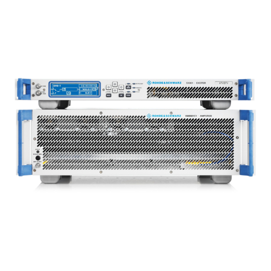
Chapter 2 Design and Characteristics 1.4.1 Exciter Fig. 17 Exciter The SX800 exciter is responsible for all signal processing of the transport stream signal up to and including an RF output signal conforming to standards. Note For detailed information about the exciter, refer to the exciter manual. 1.4.2 Exciter Switch Fig. - Page 68 Chapter 2 Design and Characteristics Fig. 19 Equipment of output stage unit; here R&S NV8304 1) Splitter 2) Amplifiers 3) Combiner 4) Absorber The output stage unit contains the following components: Splitter Amplifier Combiner Absorber The diagram below shows the entire RF path from X.E. (splitter input) up to X.A. (combiner output).
-
Page 69: Splitter
Chapter 2 Design and Characteristics Fig. 20 Block diagram of output stage unit: Example of the R&S NV8304 1.5.1 Splitter Note This section is not relevant for transmitters having only one amplifier in the rack. Fig. 21 Combiner (1) with splitter (2); here R&S NV8304 2098.0188.72 - 2.17 -... -
Page 70: Amplifier
Chapter 2 Design and Characteristics The splitter distributes the output signal of the exciter to the individual amplifiers. In addition, an integrated attenuator that is dependent on the number of outputs ensures that the RF signal is output at the right power level. The splitter is a broadband unit that operates in the frequency range 470 MHz to 862 MHz. -
Page 71: Absorber
Chapter 2 Design and Characteristics Fig. 23 Combiner (1) with splitter (2); here R&S NV8304 The RF power output from the amplifiers is merged with the correct phase via the combiner. The combiner consists of a cascade of 90° hybrids housed in a single unit. 1.5.4 Absorber This section is not relevant for transmitters having only one amplifier in the rack. - Page 72 Chapter 2 Design and Characteristics Fig. 24 Absorber The absorber resistors (dummy loads) for the combiner are located on the absorber block. When the combiner is being operated in unbalanced mode (e.g. with one or more amplifiers disabled or removed) the non-combinable component of the RF power is expelled as addi- tional heat energy via the transmitter exhaust duct.
-
Page 73: Directional Coupler Lightning Protection System
Chapter 2 Design and Characteristics Directional Coupler Lightning Protection System Fig. 25 Equipment in test lightning protection system 1) Lightning arrester 2) Directional coupler with N connector 3) Directional coupler with SMA connector 4) Directional coupler with rectifier unit The directional coupler/lightning protection system (combined lightning arrester with test points) is located at the output of the harmonics filter and contains the following compo- nents: ... -
Page 74: Directional Couplers
Chapter 2 Design and Characteristics 1.6.2 Directional Couplers Fig. 26 Directional couplers The forward and reflected power is detected at the transmitter output by means of the fre- quency-compensated directional couplers P14A (forward) and P14B (reflected). The fre- quency-compensated directional couplers output a power-proportional DC voltage to the R&S NetCCU800 transmitter control unit via the integrated rectifier circuit. -
Page 75: Directional Coupler Interface
Chapter 2 Design and Characteristics 1.6.3 Directional Coupler Interface Fig. 27 Directional coupler interface The free directional coupler interface can be used for connecting external power measuring instruments. Harmonics Filter Fig. 28 Harmonics filter; here R&S NV8304 2098.0188.72 - 2.23 -... -
Page 76: Rf Connector
Chapter 2 Design and Characteristics The FH 825 harmonics filter is used to suppress harmonics. It is a 23rd order Chebyshev filter which uses coaxial technology so that it is suitable for the rigid line system 13-30. On the signal path, the harmonics filter is located directly downstream of the combiner. The harmonics filter is varnished to reduce the surface temperature. -
Page 77: Cooling System
Chapter 2 Design and Characteristics Cooling System Fig. 30 Cooling system 1) Air intake duct 2) Fan 3) Starting capacitor 4) Differential pressure gage 5) Temperature sensor The cooling system consists of two built-in fans on active standby and contains the following components: ... -
Page 78: Intake/Exhaust Air Ducts
Chapter 2 Design and Characteristics 1.9.1 Intake/Exhaust Air Ducts Fig. 31 Intake air duct (1) and exhaust air duct (2); here R&S NV8304 with option intake air from below The air from the intake duct is drawn in by the fans and forwarded to the distribution shaft. The distribution shaft provides enough air to each amplifier to cool it. -
Page 79: Fans
Chapter 2 Design and Characteristics If the intake is at the bottom, there is no intake duct. The connecting flange is then located directly beneath the fan box. If the exhaust air is directed downward, the absorber unit is situated at the bottom and feeds into the exhaust connection. -
Page 80: Starting Capacitors
Chapter 2 Design and Characteristics 1.9.3 Starting Capacitors Fig. 33 Starting capacitor Each motor is equipped with an external starting capacitor. 2098.0188.72 - 2.28 -... -
Page 81: Differential Pressure Gages
Chapter 2 Design and Characteristics 1.9.4 Differential Pressure Gages Fig. 34 Differential pressure gages The differential pressure gages (diaphragm switches) measure the differential pressure of each fan between the fan flange (output) and the environment. Thus, fan malfunctions can be selectively sent to the transmitter control unit. 2098.0188.72 - 2.29 -... -
Page 82: Temperature Sensors
Chapter 2 Design and Characteristics 1.9.5 Temperature Sensors Fig. 35 Temperature sensors The temperature sensors measure the absolute intake and exhaust air temperatures in °C for display on the R&S NetCCU800 and monitoring in the rack controller. Note If the exhaust temperature exceeds 65 °C, the rack controller switches off the rack due to the risk of overheating. -
Page 83: Specifications
Chapter 2 Design and Characteristics Specifications Transmitter System – General Frequency range ........470 MHz to 862 MHz Standard ............ ATSC Transmission bandwidth ......6 MHz Voltage supply ........... 230 V / 400 V ± 15 % 47 Hz to 63 Hz Three-phase current (3W+N+PE) cos... -
Page 84: Transmitter System - Specific
Chapter 2 Design and Characteristics and/or SNMP agent); optional parallel I/O Interface (floating contacts and commands); optional BitBus interface to IEC 864-2 Spurious emissions Harmonics .......... 70 dBc Spurious ............. 60 dBc Noise power ratio ........ 130 dBc To adhere to national standards on the antenna interface, the transmitter may only be op- Note erated with an external output bandpass. - Page 85 Chapter 2 Design and Characteristics Connection cross-section ......2.5 mm / AWG 12 Backup fuse ..........16 A to 20 A (setting value: 16 A) (Automatic line fuse, e.g. Siemens 3VL1702-1DD33) Connection cross-section ......2.5 mm / AWG 12 Total weight (approx.) ........ 235 kg 2.2.2 R&S NV8302 Number of amplifiers .........
- Page 86 Chapter 2 Design and Characteristics Additional fuses Backup fuse (type NH gG) ......3 x 20 A Connection cross-section ......2.5 mm / AWG 10 Backup fuse ..........16 A to 20 A (setting value: 20 A) (Automatic line fuse, e.g. Siemens 3VL1702-1DD33) Connection cross-section ......
- Page 87 Broadcasting Division CHAPTER 3 INSTALLATION Printed in Germany 2095.7346.32 - 3.0 -...
- Page 89 Chapter 3 Installation CONTENTS 1 Equipment Supplied ................ 1 1.1 Integrated Transmitter Components ............1 1.2 Transmitter Components Supplied Separately ...........2 2 Overview ................... 3 3 Setting Up Transmitter ..............4 3.1 Preparations ....................4 3.1.1 Checking Structure, Flatness and General Suitability of Installation Surface ......................4 3.1.2 Preparing Floor Openings (only if Feed and Return pass through Floor) ..4 3.1.3 Arranging Connections on Transmitter Roof ..........6...
- Page 90 Chapter 3 Installation 7.2 Connecting Dummy Antenna ..............21 8 Connection Panel ................23 2098.0188.72 - 3.02 -...
-
Page 91: R&S Nv8302
Chapter 3 Installation Equipment Supplied Integrated Transmitter Components In the case of transmitters in the R&S NV8300E/V family, the following units and modules are already installed in the rack (depending on the equipment supplied): Use the tables below to check that all the relevant components have been supplied. Note Quantity Part name... -
Page 92: Transmitter Components Supplied Separately
Chapter 3 Installation Quantity Part name Type Strain relief for AC supply feed Options Hazard button kit R&S ZR800N1 2099.4506.VAR VAR: 11 = 1 button on front VAR: 12 = Button on front and rear VAR: 13 = Button on rear Parallel remote control inter- R&S ZR800F1 3562.4210.02... -
Page 93: Overview
Chapter 3 Installation Overview The transmitter is installed by following the sequence given below: Setting up the transmitter – Checking the structure, flatness and general suitability of the installation surface – Preparing openings required in the floor (only with inlets and outlets from below) –... -
Page 94: Setting Up Transmitter
Chapter 3 Installation Setting Up Transmitter Make sure that the transmitter is standing in a stable position and that ventilation is suffi- cient. During installation, the transmitter must be easily accessible from the front and rear. A Note clearance space of at least 1.2 m is necessary in order to install all components. Preparations Before setting up and installing the transmitter, you must make the following preparations: ... - Page 95 Chapter 3 Installation Fig. 1 Transmitter floor dimensioning 1) Adjustable foot (Ø 50) 2) AC supply input 3) Bottom intake (flange Ø178) 4) Bottom exhaust (flange Ø178) 5) Bottom RF output (ATV, 1 5/8 EIA) 6) Bottom RF output (DTV, 1 5/8 EIA) 7) Attachment hole (floor) 2098.0188.72 - 3.5 -...
-
Page 96: Arranging Connections On Transmitter Roof
Chapter 3 Installation 3.1.3 Arranging Connections on Transmitter Roof When making preparations for installing the station, please observe the following drawing of the transmitter roof. Fig. 2 Transmitter roof dimensioning 1) Intake (flange Ø178) 2) Exhaust (flange Ø178) 3) Remote control interface 4) Remote control interface (optional) 5) Transmitter connection panel 6) TS distributor... -
Page 97: Erecting Transmitter Rack
Chapter 3 Installation Erecting Transmitter Rack The transmitter rack can be set up using lift equipment (crane). Lifting eyes are attached to the rack roof for this purpose. Fig. 3 Lifting eyes WARNING! Do not stand under suspended racks, otherwise you could be crushed. Take the relevant safety precautions when climbing ladders, otherwise you could fall. -
Page 98: Unpacking Components
Chapter 3 Installation Using a Torx screwdriver No. 20, remove all front panels and the rear panel from the rack. This allows you to reach all the necessary units, connectors and interfaces. Pay attention to the ground connections when removing and fitting the front panels and the Note rear panel. -
Page 99: Ventilation System
Chapter 3 Installation Ventilation System The ventilation system is already installed and wired inside the transmitter. Note Connecting Air Intake/Exhaust Ducts The intake and exhaust air outlets are located either on the top or bottom of the transmitter rack, depending on your order specifications. The "Intake air from room" option is also avail- able. - Page 100 Chapter 3 Installation Fig. 5 Transmitter roof dimensioning 1) Intake (flange Ø178) 2) Exhaust (flange Ø178) 3) Remote control interface 4) Remote control interface (optional) 5) Transmitter connection panel 6) TS distributor 7) RF output (1 5/8 EIA) 2098.0188.72 - 3.10 -...
- Page 101 Chapter 3 Installation Fig. 6 Transmitter floor dimensioning 1) Adjustable foot (Ø 50) 2) AC supply input 3) Bottom intake (flange Ø178) 4) Bottom exhaust (flange Ø178) 5) Bottom RF output (ATV, 1 5/8 EIA) 6) Bottom RF output (DTV, 1 5/8 EIA) 7) Attachment hole (floor) 2098.0188.72 - 3.11 -...
-
Page 102: Connecting External Backup Fan
Chapter 3 Installation Connecting External Backup Fan If conditions at the building site make it necessary to deal with larger distances (i.e. over Note 12 m), an external fan must be used. The transmitter provides a switched phase for controlling an external contactor. Further- more if necessary you can connect an external motor protection switch with alarm button into the cooling disturbance circuit of the transmitter. -
Page 103: Checking Differential Pressure Gages
Chapter 3 Installation Fig. 8 Ventilation opening The ventilation openings on vacant slots (without amplifiers) have to be closed. Note Checking Differential Pressure Gages For the differential pressure gages to be able to measure the pressure between the fans and the environment, the covers must be removed. ... -
Page 104: Ac Power Supply
Chapter 3 Installation AC Power Supply The standard components of the transmitter are fully cabled together. The rack therefore simply needs to be connected to an external AC power supply. DANGER! Before you connect the transmitter, disconnect the external power supply cable from the power supply. -
Page 105: Connecting Transmitter Ground
Chapter 3 Installation Backup fuse Setting value Fixed value Line cross-section Siemens auto- Overload Short-circuit System type matic line fuse, VDE / UL trip trip e.g. R&S NV8303 3VL17 02-1DD33... 20 A 300 A 2.5 mm / AWG 10 R&S NV8304 3VL17 03-1DD33... - Page 106 Chapter 3 Installation AC power Main switch Q1 supply Q1.T1 Q1.T2 Q1.T3 Q1.N Grounding clamp X.PE1 1. Unscrew the rotary switch and the cover of the main switch. Fig. 11 Unscrew rotary switch and cover 2. Secure the supplied strain relief for the AC supply cable in place as shown. 2098.0188.72 - 3.16 -...
-
Page 107: Connecting External Equipment
Chapter 3 Installation Fig. 12 Strain relief for the AC supply cable 3. Loosen the locking screws on the switch housing so that you can easily insert the ca- bles. 4. Insert the cables into the corresponding openings and fasten them in place with screws. 5. - Page 108 Chapter 3 Installation External fan to (see section "Connection of External Backup Fan") External dummy antenna to (see section "Connecting Dummy Antenna") Suitably adapted dummy plugs are located at the points provided for the purpose. 1. Take the required dummy plug from the power distribution board. 2.
-
Page 109: Amplifiers
Chapter 3 Installation Amplifiers When the transmitter is delivered, one or two exciters and an R&S NetCCU800 are already mounted in the rack. The amplifiers, however, are not and must be retrofitted in the rack. Installing Amplifiers WARNING! Always make sure that the power supply is disconnected before commencing any installa- tion work on the transmitter rack. -
Page 110: Connecting Antenna/Dummy Antenna To Rf Connector
Chapter 3 Installation Connecting Antenna/Dummy Antenna to RF Connector The connection flanges for the antenna cables are uniformly 1 “ EIA for TV transmitters in the R&S NV8300 family. These flanges are located on the roof of the transmitter. Depend- ing on the transmitter station (one or more transmitters), either the antenna (RF cable or RF transmission line) or an RF connection is connected directly to a multiple combining filter. - Page 111 Chapter 3 Installation Fig. 16 RF connection with adapter Connecting Dummy Antenna The dummy antenna is only connected when putting the system into operation or for main- tenance and repair purposes. With some dummy antennas that have coolant monitoring and overtemperature monitoring, the monitoring equipment can be connected to the transmitter.
- Page 112 Chapter 3 Installation Fig. 17 Looping in an antenna patch panel 2098.0188.72 - 3.22 -...
- Page 113 Chapter 3 Installation Connection Panel The following table lists all the connectors that you may need to assign. Connection Description CANBUS X101A CAN bus data connection for additional racks or output stage A CANBUS X101B CAN bus data connection for additional racks or output stage B RS232 X232 Serial data connection for external BITBUS interface ETHERNET...
- Page 114 Chapter 3 Installation 2098.0188.72 - 3.24 -...
- Page 115 Broadcasting Division CHAPTER 4 COMMISSIONING Printed in Germany 2095.7346.32 - 4.0 -...
- Page 117 Chapter 4 Commissioning CONTENTS 1 General Information ................. 1 1.1 Preparations ....................1 1.2 Requirements ....................2 1.3 Operating R&S NetCCU800 ................2 2 Preparing for Transmitter Startup ..........3 2.1 Preparing for Local Operation ...............3 2.2 Checking and Setting System and Operating Parameters ......3 2.3 R&S NetCCU800 .....................3 2.3.1 Switching On R&S NetCCU800 ..............3 2.3.2 Changing User Type ..................3...
- Page 118 Chapter 4 Commissioning 3.1 Final Steps ....................26 3.1.1 Checking R&S NETCCU800 Status Display ..........26 3.1.2 Checking Exciter Status Display ..............27 3.1.3 Checking Output Stage Status Display ............27 3.2 Adjusting Amplifier Order Numbers to Installation Positions in Rack ..29 3.3 Clearing Event Memory ................30 4 Precorrection .................
-
Page 119: General Information
Chapter 4 Commissioning General Information Transmitters are put into operation by means of the graphical user interface of the R&S NetCCU800. Preparations Before you can put a transmitter into operation, it must first have been fully installed. Check the following list to ensure that all connections have been correctly made: ... -
Page 120: Requirements
Chapter 4 Commissioning Requirements 1. Before switching on the transmitter, check whether the exciter is set to the correct fre- quency (consistent with any diplexer or bandpass filter that may be connected). If the transmission frequency is not yet known, the transmitter should remain switched off until the frequency is set. -
Page 121: Preparing For Transmitter Startup
Chapter 4 Commissioning Preparing for Transmitter Startup Local operation of the R&S NetCCU800 includes all the information calls for the system pa- rameters and their settings, complete with intuitive graphical menus. Remote operation via a web browser is possible only if a PC or notebook is connected to the front panel of the R&S NetCCU800. -
Page 122: Entering Basic Settings
Chapter 4 Commissioning To log on with configuration rights under local control, proceed as follows: 1. From the context menu, select the menu item Change User. The Logon window opens. The current user ID is displayed to the right of Select user from list. -
Page 123: Setting Date And Time
Chapter 4 Commissioning 2. Enter the basic settings as shown in the table below. Function Explanation Display Timeout Time in minutes after which the display switches off (standby) LED Local Color of the Local LED on the front panel of the R&S NetCCU800 (yel- low, green) LED On Color of the ON LED on the front panel of the R&S NetCCU800 (yellow,... -
Page 124: Adjusting Network Settings
Chapter 4 Commissioning 1. Select NetCCU > Setup > NetCCU Setup > Date/Time. The Date/Time window opens. 2. Enter the basic settings as shown in the table below. Setting item Explanation Date Used to set the current date Local Time Used to set the local time The local time is the time of day or zone time applicable at the station. -
Page 125: Rear Ethernet Interface (Netlink)
Chapter 4 Commissioning Select NetCCU > Setup > NetCCU Setup > Network > Front Ethernet. The Front Ethernet window opens. The Front Ethernet window displays the following network settings: Display Explanation IP Address IP address of the network card Network Mask Subnet mask of the network card Speed Mode... - Page 126 Chapter 4 Commissioning 1. Select NetCCU > Setup > NetCCU Setup > Network > Rear Ethernet. The Rear Ethernet window opens. 2. Make the required settings: Setting/display Explanation IP Address IP address of the network card Network Mask Subnet mask of the network card Gateway Gateway address (specified by the network administrator) DHCP Client...
-
Page 127: Setting Transmitter Type
Chapter 4 Commissioning Notes – Manual settings for remote connection should only be entered in offline mode (context menu: Edit Offline) and then activated with Submit Changes (context menu). – The IP address must not be in the same network as the front ETHERNET interface. - Page 128 Chapter 4 Commissioning Function Explanation Power Mode Used to set the power class – Low – Medium – High Cooling System Used cooling system The following setting is preset for Power Mode "Low" or "Medium": – Air: Air cooling The following settings can be selected for Power Mode "High": –...
-
Page 129: Entering Exciter Settings
Chapter 4 Commissioning Entering Exciter Settings 2.5.1 Setting TV Standard 1. Select Exciter A ATSC > Setup > Exciter Setup > Common. The Exciter Setup > Common window opens. 2. Select the required TV standard. The table below describes the parameters in detail: Setting item Description Digital Standard... -
Page 130: Configuring Input Interfaces
Chapter 4 Commissioning 2.5.2 Configuring Input Interfaces 2.5.2.1 Specifying Data Format for Data Streams Input 1 and Input 2 1. Select Exciter A ATSC > Input > Input Config. The Input > Input Config window opens. 2. Go to Presel. Mode and select the value Auto for Input1 and Input2. The data format is recognized automatically. -
Page 131: Setting Automatic Input Switchover
Chapter 4 Commissioning 2.5.2.2 Setting Automatic Input Switchover 1. Select Exciter A ATSC > Input > Input Automatic. The Input > Input Automatic window opens. 2. Activate automatic input switchover if required, and enter the appropriate settings. The table below describes the parameters in detail: Setting item Description Preselect Input... -
Page 132: Switching Off Precorrector
Chapter 4 Commissioning Setting item Description On Input Loss For setting the behavior in the event of a defective input signal (synchro- nization error) – No Mute: The output signal is not suppressed (only effective with MFN) – Mute: The output signal is suppressed if the data rate is incorrect (rec- ommended for SFN) Type of Loss of Input Selection:... -
Page 133: Setting Transmitter Frequency
Chapter 4 Commissioning 4. Set Nonlinear Correction to Off. The nonlinear precorrector path is deactivated. The two precorrector paths must be switched on again before precorrection is carried out. Note 2.5.4 Setting Transmitter Frequency 1. Select Exciter A ATSC > RF > Synthesizer. The RF >... -
Page 134: Adjusting The I/Q Modulator
Chapter 4 Commissioning Setting item Explanation Reference Selecting the reference source for stabilization of the frequency pro- cessing (reference frequency source). The following settings are possi- ble: – Internal: Operation without external reference frequency source – External 5 MHz: Operation with external 5 MHz reference –... -
Page 135: Setting Rf Output
Chapter 4 Commissioning 2.5.6 Setting RF Output 1. Select Exciter A ATSC > RF > Output. The RF > Output window opens. 2. For normal transmission operation, enter the following settings: Setting item Setting Regulation Output Attenuation 0 dB RF Slope Modulation Slope The table below describes the adjustable parameters in detail: Setting item... -
Page 136: Specifying Behavior On Failure Of A Reference Source
Chapter 4 Commissioning Setting item Description RF Slope Correction of a slope of the amplitude frequency response in the spec- trum for equalizing subsequent components (output stage, filter). Modulation Slope Correction of a curvature of the amplitude frequency response in the spectrum for equalizing subsequent components (output stage, filter). -
Page 137: Entering Output Stage Settings
Chapter 4 Commissioning Setting item Explanation OCXO Adjust Setting for adjusting an internal OCXO frequency (for operating mode "Internal") The same setting options are available in menu window RF > Synthe- sizer. Mute on PPS Fail For setting the behavior in SFN mode in the event of failure of the exter- nal time reference. - Page 138 Chapter 4 Commissioning The table below explains the user-selectable parameters in detail: Setting Explanation Racks per OS Number of racks belonging to the output stage Outlet Temp. Fault Switch-off threshold with overtemperature If this threshold is exceeded, the rack controller shuts down the transmit- ter rack.
-
Page 139: Setting Transmitter Output Power
Chapter 4 Commissioning The table below shows all the user-selectable parameters: Setting Explanation Number of Amplifiers Used to enter the number of amplifiers installed in the rack Value: 1 to 4 RF event signaling – yes: If the minimum or maximum limits for forward and reflected power (RF Fail Limit, RF Warning Limit) are violated at the test points of the rack, warnings or fault messages are output (default setting). -
Page 140: Calibrating Power Displays
Chapter 4 Commissioning 3. Keep changing the value at Reference Voltage Vision until the desired transmitter pow- er is measured on the power meter (the table "Transmitter power and coupling attenua- tion at P14C" specifies the benchmark figures). 4. Remove the power meter from the test point P14C. Transmitter power Coupling attenuation at test point P14C... - Page 141 Chapter 4 Commissioning 2. Under Nominal Value, enter the required transmitter power that you set in the previous section. 3. Use Set Gain to measure and save the DC voltage of the forward-power test point at nominal output power. To abort, exit the Trigger: Set info window by pressing Back. To continue, confirm by Note pressing OK.
- Page 142 Chapter 4 Commissioning Function Explanation Timeout RF Fail Con- Used to select the time that the lower threshold for the forward power trol (specified as the RF Fail Limit) must be violated for before a fault mes- sage is output. For example, if a value of 3 dB has been entered as the RF Fail Limit and the actual value drops below that level for 8 seconds (typical setting for Timeout for RF Fail Control), a fault message will be output.
- Page 143 Chapter 4 Commissioning 4. Use the Set Offset command to measure and save the DC voltage of the reflected-pow- er test point at 0 W output power. To abort, exit the Trigger: Set info window by pressing Back. To continue, confirm by Note pressing OK.
-
Page 144: Completion Of Startup Procedure
Chapter 4 Commissioning Completion of Startup Procedure When the steps described in the above sections have been carried out, the transmitter is ready for operation. Each transmitter receives a test report from the final testing department complete with measurement data on every quality parameter. This means that on site com- pliance testing is only necessary at the customer's request. -
Page 145: Checking Exciter Status Display
Chapter 4 Commissioning 5. Select NetCCU > Status > Tx Status. The Tx Status window opens. 6. Check the status of the warning and fault indicators. If a transmitter is ready to operate, no warnings or faults will be signaled. 3.1.2 Checking Exciter Status Display 1. - Page 146 Chapter 4 Commissioning 2. Check the status of the warning and fault indicators. If a transmitter is ready to operate, no warnings or faults will be signaled. 3. Select Outputstage > Status > Rack Status > Rack x > Rack Controller. The Rack Status >...
-
Page 147: Adjusting Amplifier Order Numbers To Installation Positions In Rack
Chapter 4 Commissioning 5. Check the status of the warning and fault indicators. If a transmitter is ready to operate, no warnings or faults will be signaled. Adjusting Amplifier Order Numbers to Installation Positions in Rack After the transmitter system has been put into operation, entries for the amplifiers (of a par- ticular rack) are displayed in the menu path for the output stage with consecutive numbering (Amplifier 1 to max. -
Page 148: Clearing Event Memory
Chapter 4 Commissioning 2. In the Identify column, activate the function Start (starting with Device No. 1). The LEDs on the associated amplifier flash. This identifies the amplifier with the (tem- porary) order number 1. 3. Under Device, change the order number according to the position of the identified am- plifier in the rack. -
Page 149: Precorrection
Chapter 4 Commissioning Precorrection This section describes the non-linear precorrection sequence in manual mode. Functions of Nonlinear Precorrector 4.1.1 General In the basic version, the graphical user interface of the non-linear precorrector for DTV and video signals consists of the Nonlinear control panel and the FreqCorrection control pan- el. -
Page 150: Nonlinear Frequency Responses
Chapter 4 Commissioning 4.1.3 Nonlinear Frequency Responses As an additional function, the non-linear components of the DTV/video precorrection (am- plitude or phase precorrection) can be assigned a frequency response in the FreqCorrec- tion control panel, and the effect of the frequency response depends on the modulation. If the amplitude precorrection or phase precorrection is affected by an amplitude frequency response, only the "individual"... -
Page 151: General Requirements
Chapter 4 Commissioning 4.3.1 General Requirements The following requirements should be fulfilled prior to precorrection: The transmitter must be operated at its nominal power output and the system level must be adjusted at all points. Precorrection must be on, for which the Nonlinear control panel must be selected in the precorrector graphical interface. -
Page 152: Precorrection Procedure
Chapter 4 Commissioning Fig. 1 Determining system levels 4.3.3 Precorrection Procedure 4.3.3.1 Starting Precorrection Requirements The following requirements should be fulfilled prior to precorrection: The transmitter must be operated at its nominal power output and the system level must be adjusted at all points. -
Page 153: Phase Precorrection
Chapter 4 Commissioning Fig. 2 Example: DVB signal spectrum 1) Shoulder distance 2) Useful signal 3) Shoulder Start 1. Start precorrection with the phase precorrection. 2. Since phase precorrection and amplitude precorrection affect one another, repeat both precorrection procedures if necessary until the optimum result is obtained. 4.3.3.2 Phase Precorrection Proceed as follows for phase precorrection:... -
Page 154: Amplitude Precorrection
Chapter 4 Commissioning Fig. 3 Typical curve for starting precorrection with amplitude precorrection switched off 4.3.3.3 Amplitude Precorrection The procedure for amplitude precorrection is the same as that for phase precorrection. If the first interpolation point brings about an improvement, deal similarly with the other in- terpolation points. -
Page 155: Frequency-Dependent Precorrection
Chapter 4 Commissioning Fig. 4 Typical curve with both phase and amplitude precorrection switched on 4. Optimize the shoulder distance using all interpolation points again, in particular by shift- ing the interpolation point at 100%. Keep carrying out phase precorrection and amplitude precorrection alternately until no fur- ther improvement can be obtained. - Page 156 Chapter 4 Commissioning Optimizing the shoulder distance 1. First use the the Curve Data Amplitude Read and Curve Data Phase Read buttons in the Nonlinear control panel to read off the characteristics currently set in the precorrec- tor. The characteristics are displayed in the display part of the graphic. 2.
-
Page 157: Fine Adjustment Using An Existing Or Preset Characteristic
Chapter 4 Commissioning 1. Set another onset point in the upper level range >25%. 2. Optimize the shoulder distance by alternately setting the amplitude and phase regula- tors with the aid of the slopes of point 2. The slopes will then point in the opposite direction than at Point 1. Fig. - Page 158 Chapter 4 Commissioning 2098.0188.72 - 4.40 -...
Need help?
Do you have a question about the N 8000 Series and is the answer not in the manual?
Questions and answers