
Related Manuals for Federal Signal Corporation Smart Siren


Summary of Contents for Federal Signal Corporation Smart Siren
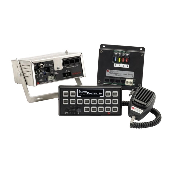
- Page 1 Relay Module is included with Model 69200 PA300-CN. PA300-CN Convergence Network Installation and Maintenance Manual 2562675B REV. B 912 Printed in U.S.A.
- Page 2 blank page...
-
Page 3: Table Of Contents
Contents Chapter 1 Safety Messages for Installers and Operators ............7 Safety Messages to Installers of Federal Signal Sound/Light Systems ............7 Safety Messages to Operators of Federal Signal Sound/Light Systems ............9 Chapter 2 An Overview of the PA300-CN .................. 11 Siren, PA, and Speakers .......................... - Page 4 Contents Mounting the Siren Amplifier ........................33 Mounting the Control Pad ...........................35 Mounting the Microphone ...........................36 Chapter 6 Setting Control Pad Options ..................38 Entering Program Mode ..........................39 Turning Off or On the 10-Second Notification Beep ...................39 Dimming or Turning Off the Button LEDs ....................39 Resetting to the Factory Default Configuration ...................39 Exiting Program Mode ..........................39 Chapter 7...
- Page 5 Contents Figures Figure 3.1 Dimensions of the control pad .......................15 Figure 3.2 Dimensions of the siren amplifier ....................15 Figure 3.3 Serial port locations on PA300-CN and connected devices ............17 Figure 3.4 PA300-CN connection for Model 660100 ..................18 Figure 3.5 Connections for two speakers ......................19 Figure 3.6 Connections for horn-ring transfer circuit ..................20 Figure 3.7 Jumper setting for GND activation of HORN RING circuit ............21 Figure 3.8 Connections for radio rebroadcast ....................22...
- Page 6 Legend, Arjent, and Raydian are registered trademarks of Federal Signal Corporation. Convergence and SignalMaster are trademarks of Federal Signal Corporation. SEMS is a trademark of Illinois Toolworks Inc. Keps is a trademark of ITW Shakeproof.
-
Page 7: Chapter 1 Safety Messages For Installers And Operators
CHAPTER 1 Safety Messages for Installers and Operators For your safety, read and understand this manual thoroughly before installing, operating, and servicing the PA300-CN. The safety messages presented in this chapter and throughout the manual are reminders to exercise extreme care at all times. In addition, read and understand the safety instructions to installers and keep it close at hand for reference. - Page 8 Chapter 1: Safety Messages for Installers and Operators Light Hazards • To be an effective warning device, warning lights produce bright light that can be hazardous to your eyesight when viewed at close range. Do not stare directly into the lighting product at a close range or permanent damage to your eyesight may occur.
-
Page 9: Safety Messages To Operators Of Federal Signal Sound/Light Systems
Chapter 1: Safety Messages for Installers and Operators • Locate the control pad so the vehicle, controls, and microphone can be operated safely. • When drilling into a vehicle structure, be sure that both sides of the surface are clear of anything that could be damaged. - Page 10 Chapter 1: Safety Messages for Installers and Operators • If a selected function does not perform properly or if any of the lamps remain illuminated when the control is off, disconnect the power connector from the control unit and contact the nearest service center.
-
Page 11: Chapter 2 An Overview Of The Pa300-Cn
CHAPTER 2 An Overview of the PA300-CN The PA300-CN is a full-featured, programmable electronic siren and light control system. State-of-the-art microprocessor technology is used to create a system with a small, compact control pad and a siren amplifier that can be installed in the trunk, under the dashboard, or under the seat of any vehicle with a 12 V negative ground system. -
Page 12: Programmable Active-Low Inputs
Chapter 2: An Overview of the PA300-CN Programmable Active-Low Inputs Control Pad Cable assembly P/N 17500063 includes 18-inch, 22 AWG wires for four active-low circuit inputs. Each input circuit can be programmed to activate with an installer-supplied switch with a current capacity of 100 mA , the SSP3000 control pad, or with the two-way switches on the steering wheel of the Ford Police Interceptor. -
Page 13: Relay Specifications (Model 690200 Pa300-Cn Only)
Chapter 2: An Overview of the PA300-CN Relay Specifications (Model 690200 PA300-CN Only) Fuse Capability AUX 1: 15 A AUX 2: 20 A AUX 3, 4: 10 A Flash Rates (Relays 3 and 4 only) 75 flashes per minute 90 flashes per minute 120 flashes per minute 200 flashes per minute 300 flashes per minute... -
Page 14: Chapter 3 Connecting The Pa300-Cn System
CHAPTER 3 Connecting the PA300-CN System Before permanently mounting the PA300-CN system, plan all wire routings and select the mounting locations for the siren amplifier/relay module and control pad. Also read and understand all instructions included with related equipment before installing it. Selecting Mounting Locations When fastened to the back of the control pad, the mounting bracket covers the wiring connectors and a supplemental control for the gain or volume of the radio rebroadcast feature. -
Page 15: Figure 3.1 Dimensions Of The Control Pad
Chapter 3: Connecting the PA300-CN System Figure 3.1 Dimensions of the control pad FRONT VIEW RIGHT SIDE VIEW 6.80 in 1.50 in (17.27 cm) (3.81 cm) 3.25 in (8.25 cm) 290A6786 Figure 3.2 Dimensions of the siren amplifier TOP VIEW FRONT VIEW 8.5 in (21.6 cm) -
Page 16: Preparing To Connect The Pa300-Cn System
Chapter 3: Connecting the PA300-CN System Preparing to Connect the PA300-CN System The PA300-CN has the following types of Convergence Network connections via cables and locking connectors included with the PA300-CN kit: Three “plug and play” serial ports that communicate on the Federal Signal Convergence Network with ■... -
Page 17: Figure 3.3 Serial Port Locations On Pa300-Cn And Connected Devices
Chapter 3: Connecting the PA300-CN System ILS System lightbars that include three models of single-level LED lightbars—Front ILS, Rear ◆ Lower ILS, and Rear Upper ILS—that mount on the inside of a vehicle windshield. Configurable options include flash patterns and functions, such as dimming, takedown lights, and alley lights. Figure 3.3 shows the three network serial connections on the back of the siren amplifier. -
Page 18: Connections To The Model 660100 Relay Module/Two-Channel Flasher
Chapter 3: Connecting the PA300-CN System Connections to the Model 660100 Relay Module/Two-Channel Flasher The Model 660100 Relay Module/Two Channel Flasher is included with the Model 690200 PA300-CN siren amplifier. It controls up to four different devices of which two can be activated as a two-channel flasher. -
Page 19: Connections For One Or Two Speakers (Cable Assembly P/N 1461907)
Chapter 3: Connecting the PA300-CN System Connections for One or Two Speakers (Cable Assembly P/N 1461907) The PA300-CN is designed to operate to operate with one 11-ohm impedance speaker or two 11-ohm impedance, low power (58 W) or high power (100 W), speakers connected in parallel and in phase. WIRING PRECAUTION—Do not connect the brown zip cord wires to the speaker. -
Page 20: Connections For Horn Ring Transfer (Cable Assembly P/N 1461907)
Chapter 3: Connecting the PA300-CN System Connections for Horn Ring Transfer (Cable Assembly P/N 1461907) The default setting for the slide switch transfers the horn-ring activation of the siren amplifier in Slide Switch 2 and 3. In Slide Switch 2, a press of the horn button activates the Manual tone. In Slide Switch 3, each press of the horn button cycles through siren functions. -
Page 21: Figure 3.7 Jumper Setting For Gnd Activation Of Horn Ring Circuit
Chapter 3: Connecting the PA300-CN System DETERMINE CURRENT FOR HORN—The horn ring transfer circuit of the siren can switch a maximum of 5 A. Some vehicles do not have a horn relay and consequently will draw more than 5 A when the vehicle horn is activated. -
Page 22: Connections For Radio Rebroadcast (Cable Assembly P/N 1461907)
Chapter 3: Connecting the PA300-CN System Connections for Radio Rebroadcast (Cable Assembly P/N 1461907) The radio rebroadcast feature allows incoming two-way radio messages to be amplified by the PA300-CN siren amplifier and rebroadcast over the siren speakers. For instructions on adjusting the gain, see “Setting the Gain for Radio Rebroadcast”... -
Page 23: Connections For The Park Input Circuit (Cable Assembly P/N 1461907)
Chapter 3: Connecting the PA300-CN System Connections for the Park Input Circuit (Cable Assembly P/N 1461907) The Park Input circuit sends a signal to the siren amplifier/relay module to mute all siren functions except Air Horn and Manual when the vehicle transmission is shifted into park or neutral. The Siren Mute option is configured with the Convergence Network Configuration Software. -
Page 24: Connecting The Control Pad
Chapter 3: Connecting the PA300-CN System Figure 3.10 Connections for the PARK INPUT circuit 290A6794 CIRCUIT PROVIDING +12 V or GND (SET JUMPER IN SIREN) Connecting the Control Pad In addition to the connection through the 25-foot Convergence Network cable (P/N 1751532) shown in Figure 3.3 on page 17, the control pad has: Connections for four active-low input circuits that activate when pulled to ground. -
Page 25: Connecting Ignition Power To The Control Pad
Chapter 3: Connecting the PA300-CN System Figure 3.11 Active-low input connections 22 AWG CABLE ASSY. P/N 17500063 INPUT 1 THROUGH 4 GRAY 1 GROUND ACTIVE (ACTIVE LOW) PURPLE 2 WHITE/YELLOW 3 BLUE 4 −GND Connecting Ignition Power to the Control Pad To connect the control pad to ignition power: See Figure 3.11. -
Page 26: Figure 3.13 Wiring For Ignition Power To Control Pad
Chapter 3: Connecting the PA300-CN System Use a multimeter to determine which source provides power when the vehicle key is in the ignition position. See Figure 3.13. Connect the red lead from the control pad to the switched side of the vehicle ignition harness. -
Page 27: Connecting The Federal Signal Microphone (P/N 258B8577-03)
Chapter 3: Connecting the PA300-CN System Connecting the Federal Signal Microphone (P/N 258B8577-03) The Federal Signal microphone provides high-quality voice reproduction in for public address over the siren speakers. The microphone push-to-talk switch overrides all siren functions, except radio rebroadcast, for instant PA use. The microphone connection is not required for the siren to operate properly. -
Page 28: Connecting The Pa300-Cn System To The Battery
Chapter 3: Connecting the PA300-CN System Connecting the PA300-CN System to the Battery This section has instructions for making the final electrical connections from the siren to the battery. These connections supply power to the PA300-CN system. Wiring of an amperage capacity sufficient to handle the total vehicle electrical loads is required to extend the red and black leads. -
Page 29: Figure 3.16 Power Connections For Convergence Network
Figure 3.16 Power connections for Convergence Network POSITIVE (+) GROUND (–) BLACK 20 A FUSE 290A6795 PA300-CN Siren Amplifier... -
Page 30: Chapter 4 Setting The Gain For Radio Rebroadcast And Pa
CHAPTER 4 Setting the Gain for Radio Rebroadcast and PA The radio rebroadcast feature allows incoming two-way radio messages to be amplified by the siren amplifier/relay module and rebroadcast over the siren speakers of the PA300-CN system. The feature overrides all sirens functions. Button 7 is programmed as the default control for radio rebroadcast. The gain control for radio rebroadcast is a recessed potentiometer on the front of the siren amplifier (Figure 4.2 on page 31). -
Page 31: Figure 4.2 Gain Controls For Pa And Radio Rebroadcast (Pa300-Cn)
Chapter 4: Setting the Gain for Radio Rebroadcast and PA Stand outside of the vehicle and note the volume level of the radio rebroadcast. If the volume is too loud or too soft, insert a small flat-head screwdriver in the gain control port for RADIO REBROADCAST on the front of the siren amplifier (Figure 4.2). -
Page 32: Setting The Gain For Public Address (Pa)
Chapter 4: Setting the Gain for Radio Rebroadcast and PA Setting the Gain for Public Address (PA) To adjust the PA gain: Stand outside the vehicle in an enclosed area and press the push-to-talk button on the control pad microphone. Speak into the microphone in a normal tone of voice. See Figure 4.1 on page 32. -
Page 33: Chapter 5 Mounting The Siren Amplifier, Control Pad, And Mic
CHAPTER 5 Mounting the Siren Amplifier, Control Pad, and Mic The next step in the installation after wiring and connecting the PA300-CN system is to permanently mount the siren amplifier and control pad in the vehicle. Verify that the mounting locations you selected earlier are safe for installing these components. -
Page 34: Figure 5.1 Brackets Attached To Pa300-Cn
Chapter 5: Mounting the Siren Amplifier, Control Pad, and Mic UNIT REQUIRES UNRESTRICTED AIR FLOW—The siren amplifier is cooled by an internal fan. Do not install it in areas where the air flow is restricted. Do not mount the unit near a heater duct or under the hood. UNIT IS NOT WATERPROOF—The housing of the siren amplifier is NOT waterproof. -
Page 35: Mounting The Control Pad
Chapter 5: Mounting the Siren Amplifier, Control Pad, and Mic USE MOUNTING HARDWARE AS SHOWN—To avoid damage to the siren amplifier, the 1/4"-20 x 1/2" hex-head cap screws and the 1/4" split lockwashers must be used as shown in Figure 5.1 on page 34. Loosely secure the siren amplifier to the mounting bracket with 1/4"-20 x 1/2"... -
Page 36: Mounting The Microphone
Chapter 5: Mounting the Siren Amplifier, Control Pad, and Mic Use the mounting bracket as a template and scribe two drill-position marks at the selected mounting location. Drill two pilot mounting holes at the drill position marks. See Figure 5.3. Secure the mounting bracket to the mounting surface with the #10 thread-forming screws. -
Page 37: Figure 5.4 Installation Of Microphone Mounting Clip
Chapter 5: Mounting the Siren Amplifier, Control Pad, and Mic Figure 5.4 Installation of microphone mounting clip MIC MOUNTING CLIP TYPE A, #6 SCREWS (3) BUTTON ON BACK OF MIC 290A6846 PA300-CN Siren Amplifier... -
Page 38: Chapter 6 Setting Control Pad Options
CHAPTER 6 Setting Control Pad Options The PA300-CN control pad has these configurable features: A notification beep that sounds every ten seconds when one or more functions or devices in the PA300- ◆ CN system, such as a lightbar, is activated. The default setting is “on.” Step-through selection of one of four levels of LED dimming, including “off.”... -
Page 39: Entering Program Mode
Chapter 6: Setting Control Pad Options Entering Program Mode See Figure 6.1. To set the keypad options, first enter Program Mode: Press and hold Button 6 while powering up the control pad. During the long beep, release Button 6. The control pad beeps continuously. Verify that the first amber LED is on. -
Page 40: Table 6.1 Control Pad Default Configuration
Chapter 6: Setting Control Pad Options Table 6.1 Control pad default configuration Relay configurations in bold text are for the Four-Channel Relay Module, which is included with the Model 69200 PA300-CN siren amplifier. Lightbar configurations in bold text are for lightbars equipped with the designated hardware and software options. -
Page 41: Figure 6.2 Default Configuration For Steering Wheel Switches Wired To Control Pad
Chapter 6: Setting Control Pad Options Figure 6.2 Default configuration for steering wheel switches wired to control pad SLIDE SWITCH 3 SLIDE SWITCH 1 BUTTON 2 SLIDE SWITCH 2 Figure 6.3 LED programming indicators on the control pad The control pad legends in the illustration are for a typical configuration. The PA300-CN siren amplifier system includes additional legends. -
Page 42: Chapter 7 Control Pad Legends And Safety Messages
CHAPTER 7 Control Pad Legends and Safety Messages To complete the installation, the PA300-CN system includes: ◆ A scored sheet of replaceable keypad legends that identify the functions of the control pad buttons (part no. 181460). Before installing the legends, configure the operation of the control pad with the PA300-CN configuration software (see the "Convergence Network Control Pad Configuration Software Manual,"... -
Page 43: Distributing The Safety Message Card
Chapter 7: Control Pad Legends and Safety Messages Distributing the Safety Message Card Give the operator of the PA300-CN system the card entitled “Safety Message to Operators of Federal Signal Light/Sound Systems” (part no. 256B691) (Figure 7.2). The operator must read and understand the safety instructions and keep the card in the vehicle for reference. -
Page 44: Chapter 8 Safety Messages To Personnel Servicing Federal Signal Electronic Sirens
CHAPTER 8 Safety Messages to Personnel Servicing Federal Signal Electronic Sirens The people’s lives depend on your proper servicing of Federal Signal products. It is important to read and follow all instructions shipped with the products. |In addition, listed below are some other safety instructions and precautions you should follow: •... -
Page 45: Chapter 9 Servicing The Pa300-Cn
CHAPTER 9 Servicing the PA300-CN Replacement parts are available for the control pad and siren amplifier. See "Ordering Replacement parts on page 48. Replacing the Slide Switch The slide switch can be removed from the control pad for replacement or service without disassambling the entire control pad. -
Page 46: Figure 9.1 Control Pad Removed From Mounting Surface
Chapter 9: Servicing the PA300-CN Figure 9.1 Control pad removed from mounting surface 1/4" LOCKWASHER, EXT. TOOTH (2) 1/4-20 x 3/4" HINGE SCREW, HEX HEAD (2) 290A6484 Disconnect the cables and leads from the back of the control pad. Figure 9.2 Control pad removed from mounting brackets #6 SPLIT LOCKWASHER (2) #6-32 x 1/4"... -
Page 47: Replacing The Slide Switch In The Control Pad
Chapter 9: Servicing the PA300-CN Replacing the Slide Switch in the Control Pad To replace the slide switch: See Figure 9.3. Remove and retain the four Phillips #6-32 x 5/16" screws securing the control pad base to the control pad assembly. Remove and retain the control pad base. -
Page 48: Reinstalling The Control Pad
1/4" external-tooth lock washers and 1/4-20 x 3/4" hinge screws.) Getting Technical Support and Service Federal Signal Corporation will service your equipment or provide technical assistance with any problems that cannot be handled locally. Any product returned to Federal Signal for service, inspection, or repair must be accompanied by a Return Material Authorization number. -
Page 49: Table 9.1 Pa300-Cn Siren Replacement Parts
Chapter 9: Servicing the PA300-CN Table 9.1 PA300-CN siren replacement parts Description Part Number Transistor, Output, BUT70W 125467 Transformer, Output 1461358 Fuse, 20 A, 3 AG, 32 V 14A127 Serial Cable, 4 feet 1751357-04 Serial Cable, 25 feet 1751357-02 Mic/Volume Assy., 4 feet 1751471 Mic/Volume Assy., 25 feet 1751471-1... -
Page 50: Returning A Product To Federal Signal
• Write the RMA number down, so that you can easily check on status of the returned equipment. Send all material with the issued RMA Number to: Federal Signal Corporation 2645 Federal Signal Drive University Park, IL 60484-3167 Attn: Service Department... - Page 51 blank page...
- Page 52 2645 Federal Signal Drive, University Park, IL 60484-3167 Tel.: (800) 264-3578 • Fax: (800) 682-8022 www.fedsig.com © 2012 Federal Signal Corporation...
Need help?
Do you have a question about the Smart Siren and is the answer not in the manual?
Questions and answers