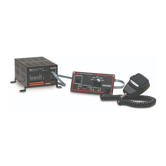
Federal Signal Corporation PA4000 Installation, Operation And Service Instructions
Electronic siren
Hide thumbs
Also See for PA4000:
- Installation, operation and service instructions (19 pages) ,
- Installation maintenance and service manual (21 pages) ,
- Installation and maintenance instructions manual (28 pages)

Related Manuals for Federal Signal Corporation PA4000


Summary of Contents for Federal Signal Corporation PA4000
- Page 1 MODEL PA4000 ELECTRONIC SIREN Distributed By: INSTALLATION, OPERATION, AND SERVICE INSTRUCTIONS...
-
Page 2: Limited Warranty
LIMITED WARRANTY The Signal Division, Federal Signal Corporation (Federal), warrants each new product to be free from defects in material and workmanship, under normal use and service, for a period of two years on parts replacement and one year on labor from the date of delivery to the first user-purchaser. -
Page 3: General Description
• Park-Siren Deactivator can deactivate siren The Model PA4000 is designed to drive one or tones when the vehicle is shifted into two 100 watt speakers. Using two 100-watt speakers PARK. -
Page 4: Section Ii Specifications
SECTION II SPECIFICATIONS Input Voltage ............. 11 Vdc to 16 Vdc Polarity ............... Negative ground electrical systems only Standby Current ..........250mA (backlighting extinguished) 13A ±1A (at 13.6V with 5.5-ohm load) Operating Current (Control Head & Ampl.) ..Frequency Range ..........725 to 1600 Hz (nominal) Cycle Rate ............ -
Page 5: Section Iii Installation
SECTION III INSTALLATION SAFETY MESSAGE TO INSTALLERS ELECTRONIC SIRENS • Sound output will be severely reduced if any objects are WARNING in front of the speaker. If maximum sound output is The lives of people depend on your proper installation and required for your application, you should ensure that the servicing of Federal products. -
Page 6: Amplifier Installation
3-1. UNPACKING. 3-3. CONTROL HEAD INSTALLATION. After unpacking the Model PA4000, examine it WARNING for damage that may have occurred in transit. If the equipment has been damaged, file a claim immedi- When installing equipment inside air bag ately with the carrier stating the extent of the equipped vehicles, the installer MUST ensure damage. -
Page 7: Electrical Installation
Speaker. 3-4. ELECTRICAL INSTALLATION. The unit is designed to operate with WARNING one 11-ohm impedance speaker (100W) or two 11- When installing equipment inside air bag ohm impedance speakers (100W). equipped vehicles, the installer MUST ensure that the equipment is installed ONLY in areas When using one 100W speaker, use 18 recommended by the vehicle manufacturer. - Page 8 CONTROL HEAD SHOWN HERE RELAY IGNITION SWITCH 290A2697B DASH LIGHT OR IGNITION SWITCH Figure 3-1. PA4000 Wiring. Aux Out. Horn Ring Cable. NOTE The horn ring cable assembly, located in the accessory kit, is a 4-wire cable terminating in an This output is activated any time the siren is orange edge connector.
- Page 9 Failure to observe this WARNING will result When making the power connections to the in fire, burns and blindness. PA4000, each wire must be terminated with an appropriate 1/4" female, insulated, quick-connect Connect the red (+) wire to the positive (+) terminal.
-
Page 10: Section Iv Operation
SECTION IV OPERATION SAFETY MESSAGE TO OPERATORS OF FEDERAL SIGNAL ELECTRONIC SIRENS AND LIGHT/SOUND SYSTEMS • Frequently inspect the speaker to ensure that WARNING it is clear of any obstruction, such as mud or The lives of people depend on your safe opera- snow, which will reduce maximum sound tion of Federal products. - Page 11 4-3. HORN RING SWITCH. All controls utilized during normal operation of The horn ring switch determines the function the Model PA4000 are located on the Control Head of the vehicle horn ring. (see figure 4-1). In the center position, the vehicle’s horn 4-2.
- Page 12 “Press and Hold” features. 4-11. PA AND RADIO GAIN ADJUSTMENT. 4-7. AUX IN FUNCTION. The PA4000 comes from the factory with the PA and radio gain set to maximum. To decrease the gain If installed, set the selector to switch to the settings, proceed as follows while referring to figure MAN position.
- Page 13 Most of the component electronic parts used in along with proficiency in the installation and the Model PA4000 are standard items that can be obtained from any radio or electronics supply shop. service of safety warning equipment. Always...
- Page 14 Heat easily impairs transistors, capacitors and circuit boards. It is CAUTION therefore advisable to use longnose pliers or a similar Before reinstalling the repaired PA4000, heat sink on the lead being soldered. make certain that the speaker(s) is (are) not defective.
-
Page 15: Replacement Parts List
125B437B Fuse, 20A, 32V 148A142A LP1, 2 Lamp, Panel 149A120 Insulator (Q106, Q109) 235A150A Amplifier Power Circuit Board, PA4000 2001191A-01 (with parts installed) Amplifier Power Circuit Board, PA4000NY 2005002A-02 (with parts installed) Amplifier Logic Circuit Board 2005001B (with parts installed) - Page 16 255292C REV. C 405 Printed in U.S.A.
Need help?
Do you have a question about the PA4000 and is the answer not in the manual?
Questions and answers