Federal Signal Corporation e-Q2B Installation Maintenance And Service Manual
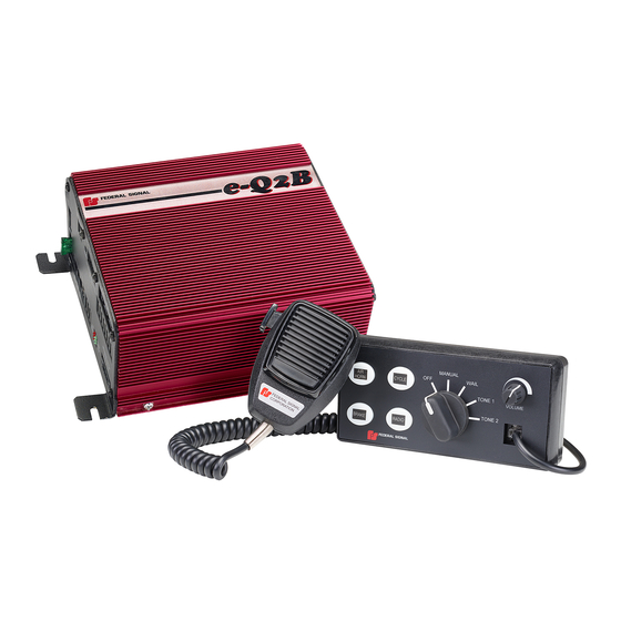
Electronic siren system
Hide thumbs
Also See for e-Q2B:
- Installation maintenance and service manual (60 pages) ,
- Instruction sheet (8 pages)

Related Manuals for Federal Signal Corporation e-Q2B


Summary of Contents for Federal Signal Corporation e-Q2B
- Page 1 Electronic Siren System Installation, Maintenance, and Service Manual Distributed By: 255394D REV. D 0315 Printed in U.S.A.
- Page 2 blank page...
-
Page 3: Table Of Contents
Connecting the Switch Input for the Model e-Q2B-200-RCFD ............20 Connecting Speakers to the e-Q2B ....................21 Connecting the e-Q2B to the Rumbler 2 Low Frequency Amplifier ..........26 Enabling the Horn-Ring Transfer of Siren Tones ................26 Enabling Radio Rebroadcast Over the Siren Speakers ..............28 Connecting the PARK Detection Circuit ..................29... - Page 4 Testing the Installation ..........................41 Distributing the Safety Message Card ....................42 Applying the Siren Safety Labels in the Vehicle ..................42 Chapter 7 Operating the Standard e-Q2B Siren System ............43 Siren Tones .............................43 Siren Priorities ............................43 Manual Mode ............................44 Cycle Foot Switch/Push Button .......................44 Brake Foot Switch/Button .........................44...
- Page 5 Contents Tables Table 2.1 Kit contents: Models e-Q2B-100 and e-Q2B-200 (standard control head) .........14 Table 2.2 Kit contents: Models e-Q2B-100 and e-Q2B-200 (flush-mount control head) ......14 Table 2.3 Kit contents: Model e-Q2B-200-RCFD ..................15 Table 10.1 Replacement parts ........................57 Figures Figure 3.1 Dimensions of the control head ....................17 Figure 3.2 Dimensions of the siren amplifier .....................17...
- Page 6 Figure 10.1 Location of set screw in selector knob ...................52 Figure 10.2 PA volume knob replacement ....................53 Figure 10.3 Control head removed from mounting surface ...............54 Figure 10.4 Fuse replacement in the siren amplifier .................56 Figure 10.5 Mounting Template for Flush-Mount Control Head...............59 e-Q2B Siren System...
-
Page 7: Chapter 1 Safety Messages For Installers And Operators
For your safety, read and understand this manual thoroughly before installing, operating, and servicing the e-Q2B Siren Amplifier. The safety messages presented in this chapter and throughout the manual are reminders to exercise extreme care at all times. In addition, read and understand the safety instructions to installers (doc. -
Page 8: During Installation
• Locate the control head so the vehicle, controls, and microphone can be operated safely. • When drilling into a vehicle structure, be sure that both sides of the surface are clear of anything that could be damaged. e-Q2B Siren System... -
Page 9: Safety Messages To Operators Of Federal Signal Sound/Light Systems
In order to be an effective warning device, this product produces bright light that can be hazardous to your eyesight when viewed at a close range. Do not stare directly into this lighting product at a close range or permanent damage to your eyesight may occur. e-Q2B Siren System... - Page 10 A magnet mounting system should not be used on vehicles with vinyl tops. ✓ To prevent sliding of light assembly on mounting surface, quick acceleration and hard stops ✓ should be avoided. Failure to follow these precautions may result in property damage, serious injury, or death. e-Q2B Siren System...
-
Page 11: Chapter 2 An Overview Of The E-Q2B Siren System
Federal Signal Q siren. Using DSP circuitry, the e-Q2B amplifier is able to reproduce the true Q sound, rather than relying on a simple digital recording. The DSP enables the product to function either manually or automatically for hands-free operation. -
Page 12: Convergence Network Control Head
Chapter 2: An Overview of the e-Q2B Siren System Convergence Network Control Head The Convergence Network control head digitally transmits and prioritizes end-user commands. The control head/amplifier interface uses solid-state digital decoding, which minimizes interconnection complexity. The control head allows the user to operate several siren functions. The traditional Q Wail can be activated in automatic or manual modes. -
Page 13: Siren Specifications: 200 Watts
Chapter 2: An Overview of the e-Q2B Siren System Siren Specifications: 200 Watts Operating Current 20 A (nominal) (13.6 V battery, 5.5-ohm load at high power) Frequency Range 725 to 1600 Hz Nominal Cycle Rate Wail: 12 cycles per minute... -
Page 14: E-Q2B Kit Contents
Chapter 2: An Overview of the e-Q2B Siren System e-Q2B Kit Contents After unpacking the kit, examine it for damage that may have occurred in transit. If the product has been damaged, file a claim immediately with the carrier stating the extent of damage. Carefully check all envelopes, shipping labels, and tags before removing or destroying them. -
Page 15: Table 2.3 Kit Contents: Model E-Q2B-200-Rcfd
Chapter 2: An Overview of the e-Q2B Siren System Table 2.3 Kit contents: Model e-Q2B-200-RCFD Qty. Description Part Number Connector, 4-Position, Speaker 140417-04 Connector, 3-Position, Power 140535 Connector, 12-Position 140584-12 Card, Safety Instructions 256B691 Label, Warning, Siren/Speaker 1612339 e-Q2B Siren System... -
Page 16: Chapter 3 Wiring The E-Q2B Siren System
To facilitate the installation of the e-Q2B, select mounting locations for the control head and the siren amplifier before permanently mounting them in the vehicle. After completing the wiring described in this chapter, refer to the instructions for mounting the control head and the siren amplifier in Chapter 5 on page 36. -
Page 17: Figure 3.1 Dimensions Of The Control Head
Chapter 3: Wiring the e-Q2B Siren System Wiring connectors are located on the siren amplifier. Ground, ignition, and power connections are located on the three-position, pluggable, terminal block. To maintain the reliability of the siren amplifier, do not block the air vents or the fan (Figure 3.2). -
Page 18: Wiring The Siren Amplifier
To prepare the vehicle for the electrical installation of the e-Q2B Siren System: After planning where to route the wires and cables for the e-Q2B Siren System components—such as Federal Signal warning lights, directional lights, and speakers—drill the holes for the wiring. -
Page 19: Connecting The Foot Switches For Cycle, Brake, And Air Horn
Chapter 3: Wiring the e-Q2B Siren System To provide strain relief, secure the cables with installer-supplied clamps and hold-downs. Insert the modular connector at the end of each cable into one of the three serial ports. Figure 3.3 Serial port locations... -
Page 20: Connecting The Switch Input For The Model E-Q2B-200-Rcfd
AIR HORN Connecting the Switch Input for the Model e-Q2B-200-RCFD The Model e-Q2B-200-RCFD siren is designed to operate without a control head. The siren produces a continuous e-Q wail tone while the input is activated. The foot switch input is CYCLE connected to the front of the siren amplifier through the 2 x 6 plug-in terminal block. -
Page 21: Connecting Speakers To The E-Q2B
The Model e-Q2B-200 operates one 200-watt speaker or two 100-watt speakers with an impedance of 11 ohms. The Model e-Q2B-100 operates one 100-watt speaker with an impedance of 11 ohms. The e-Q2B-200 siren amplifier is designed to operate optimally with a Federal Signal BP200-Q or BP200-EF 200-watt speaker system, which is not included as part of the electronic siren. -
Page 22: Figure 3.6 E-Q2B 200-Watt Speaker Connections (Bp200-Q Or Bp200-Ef)
THAT IS 18 AWG OR THICKER 290A6805 Connecting Two BP100 or ES100 Speakers to the e-Q2B-200 To connect the two 11-ohm, 100-watt speakers to the Model e-Q2B-200 siren amplifier: Mount the e-Q2B Siren System components according to the instructions included with each product. -
Page 23: Figure 3.7 E-Q2B 200-Watt Speaker Connections With Two 100-Watt Speakers
(–) wire from Speaker A is terminated in the –GRN position. To prevent fretting or disconnection, tighten the two screws on the four-position speaker connector. Figure 3.7 e-Q2B 200-watt speaker connections with two 100-watt speakers MODEL eQ2B-200 1. LOOSEN SCREW. -
Page 24: Figure 3.8 Bp100 100-Watt Speaker Connections
Chapter 3: Wiring the e-Q2B Siren System Connecting One BP100 Speaker to the e-Q2B-100 To connect one 11-ohm, 100-watt speakers to the Model e-Q2B-100 siren amplifier: Mount the e-Q2B Siren System components according to the instructions included with each product. -
Page 25: Figure 3.9 Rumbler 2 Connections To The E-Q2B
Chapter 3: Wiring the e-Q2B Siren System Figure 3.9 Rumbler 2 connections to the e-Q2B GREEN WHITE BLACK e-Q2B Siren System... -
Page 26: Connecting The E-Q2B To The Rumbler 2 Low Frequency Amplifier
Connecting the e-Q2B to the Rumbler 2 Low Frequency Amplifier The e-Q2B has a Rumbler audio output that enables it to interface to a Federal Signal Rumbler 2 siren amplifier. The Rumbler 2 intersection-clearing system uses the output of the e-Q2B siren amplifier to synthesize a low frequency signal. -
Page 27: Figure 3.10 Connections For Horn-Ring Transfer
Chapter 3: Wiring the e-Q2B Siren System Figure 3.10 Connections for horn-ring transfer PARK BRAKE GRND CYCLE REMOTE MIC RADIO RING HORN RMBLR RMBLR RADIO RADIO ENBL RADIO 12-POSITION 1. INSERT SCREWDRIVER TENSION CLAMP TO OPEN TENSION CLAMP. CONNECTOR 2. SLIP WIRE INTO CONNECTOR. -
Page 28: Enabling Radio Rebroadcast Over The Siren Speakers
Chapter 3: Wiring the e-Q2B Siren System Enabling Radio Rebroadcast Over the Siren Speakers To enable incoming two-way radio messages to be amplified by the siren amplifier and rebroadcast over the siren speakers: NOTE: The 12-position tension clamp connector accepts 18 AWG to 22 AWG wire. The recommended length of insulation to strip from the wires for insertion into the connector is 0.275 in (0.7 mm). -
Page 29: Connecting The Park Detection Circuit
Chapter 3: Wiring the e-Q2B Siren System Connecting the PARK Detection Circuit The PARK detection circuit sends a signal to the siren amplifier to mute all siren functions when the vehicle transmission is shifted into park or neutral. The circuit can detect a +12 V signal or a –BAT signal. -
Page 30: Connecting The Control Head
Plug the other end of the cable into the connector on the back of the control head. To provide strain relief, secure the cables with installer-supplied clamps and hold-downs. Figure 3.13 Convergence Network connection between e-Q2B and control head FEDERAL SIGNAL... -
Page 31: Connecting The Federal Signal Microphone (P/N 258B8577-03)
Chapter 3: Wiring the e-Q2B Siren System Connecting the Federal Signal Microphone (P/N 258B8577-03) The Federal Signal microphone provides high quality voice reproduction in for public address over the siren speakers. The microphone push-to-talk switch overrides all siren functions, except radio rebroadcast, for instant PA use. -
Page 32: Connecting The E-Q2B System To The Battery
Chapter 3: Wiring the e-Q2B Siren System Connecting the e-Q2B System to the Battery The e-Q2B is supplied with a three-conductor, 20-foot power cable. The cable uses a three-position male connector The installer-supplied red (positive) and black (negative ground) power leads from the siren amplifier to the vehicle battery should be as short and direct as possible. -
Page 33: Figure 3.15 Connections For Power, Ground, And Ignition
Chapter 3: Wiring the e-Q2B Siren System To prevent fretting or disconnection, tighten the screws on the connector. Figure 3.15 Connections for power, ground, and ignition 1. LOOSEN SCREW. 2. INSERT STRIPPED WIRE IN CONNECTOR. 3. TIGHTEN SCREW. 30 AMP... -
Page 34: Chapter 4 Setting The Gain For Radio Rebroadcast And Pa
(Figure 4.2) on page 35. For public address, the e-Q2B Siren System includes a microphone that connects to a serial port on the front of the control head. When the operator presses the microphone push-to-talk button and speaks into the microphone, the operator’s voice is amplified and broadcast over the siren speakers. -
Page 35: Setting The Gain For Public Address (Pa)
Figure 4.3 Gain control for public address KNOB FOR ADJUSTING PA VOLUME MANUAL VOLUME CONTROL WAIL ONLY WORKS FOR CYCLE HORN CONTROL HEAD MIC YELP VOLUME JACK, NOT SIREN MIC JACK PRTY BRAKE RADIO 290A6816 e-Q2B Siren System... -
Page 36: Chapter 5 Mounting The Siren Amplifier And Control Head
Mounting the Siren Amplifier and Control Head The next step in the installation after wiring and connecting the e-Q2B Siren System is to permanently mount the siren amplifier and control head in the vehicle. Verify that the mounting locations you selected earlier are safe for installing these components. -
Page 37: Mounting The Standard Control Head
For directions on mounting the flush-mount control head, see page 39. The standard control head comes with two mounting brackets and mounting hardware. Tools needed: ✔ Drill with #9 drill bit ✔ Phillips screwdriver ✔ 7/16" nut driver ✔ Pencil or felt-tip pen for marking drill position locations e-Q2B Siren System... -
Page 38: Figure 5.2 Bracket Attached To Back Of Control Head
Figure 5.3 Brackets attached to control head and mounting surface PEM-NUTS (ATTACHED TO BRACKET) 1/4" LOCKWASHER, EXT. TOOTH (2) 1/4-20 x 3/4" HINGE SCREW, HEX HEAD (2) #10 SCREW, THD. FORMING (2) MOUNTING SURFACE BRACKET (2 OF 2) 290A6819 e-Q2B Siren System... -
Page 39: Mounting The Flush-Mount Control Head
Select a mounting location for the control head (Figure 5.4). The control head must be mounted within convenient reach of the operator, typically in the vehicle console. Figure 5.4 Flush-mount control head MOUNTING SURFACE A I R #6 PHILLPS THREAD- FORMING SCREW (4) 290A6796 e-Q2B Siren System... - Page 40 Drill a mounting hole 0.104" in diameter at each of the four scribed marks. Use a sabre saw to cutout the scribed opening for the light. After completing the wiring of the e-Q2B system, insert the control head into the cutout and secure it with the four supplied #6B screws.
-
Page 41: Chapter 6 Final Preparations Of The E-Q2B Siren System
Testing the Installation Test the e-Q2B Siren System to verify that it is operating properly. Be sure to note the status of the LED indicators on the front of the siren amplifier (Figure 6.1). -
Page 42: Distributing The Safety Message Card
Applying the Siren Safety Labels in the Vehicle The e-Q2B Siren System kit includes a sheet of two labels with siren safety messages (part no. 1612339) (Figure 6.2). These labels must be installed in the vehicle in which the system is installed. Place these labels in areas that are clearly visible to operators and passengers. -
Page 43: Chapter 7 Operating The Standard E-Q2B Siren System
This chapter describes the standard siren controls (control head 8616058) and how to operate them. (For instructions on operating the eQ2B-CAL siren system, see Chapter 8 on page 47.) The e-Q2B Siren System is controlled through the control head, which has a rotary switch, four push buttons, and one volume control for public address. -
Page 44: Manual Mode
Chapter 7: Operating the Standard e-Q2B Siren System functions. For example, when WAIL is selected and the AIR HORN push button or foot switch is activated, the push button or switch is released, the WAIL tone sounds over the tone. When the... -
Page 45: Radio Rebroadcast
Chapter 7: Operating the Standard e-Q2B Siren System Radio Rebroadcast To rebroadcast incoming radio transmissions through the siren speakers, turn the rotary switch to function and press the radio switch to the ON position. The volume is factory-set but MANUAL can be adjusted by a potentiometer on the front of the siren amplifier. -
Page 46: Horn Ring
Chapter 7: Operating the Standard e-Q2B Siren System Horn Ring The e-Q2B horn-ring transfer function uses the vehicle horn switch to toggle between siren tones. The first tap of the vehicle horn button transfers the siren to the next tone. A second tap transfers to the next tone in the sequence. -
Page 47: Chapter 8 Operating The E-Q2B-Cal Siren System
This chapter describes the CAL model siren controls and how to operate them. For instructions on operating the standard eQ2B siren system, see Chapter 7 on page 43. The e-Q2B-CAL Siren System is controlled through the control head, which has a rotary switch, four push buttons, and one volume control for public address. -
Page 48: Manual Mode
Chapter 8: Operating the e-Q2B-CAL Siren System AIR HORN tone sounds over the WAIL tone. When the AIR HORN push button or switch is released, the tone continues. Public Address, Radio Rebroadcast, and override siren tones. WAIL AIR HORN Manual Mode... -
Page 49: Radio Rebroadcast
Chapter 8: Operating the e-Q2B-CAL Siren System Radio Rebroadcast To rebroadcast incoming radio transmissions through the siren speakers, turn the rotary switch to the function and press the radio switch to the ON position. The volume is factory-set MANUAL but can be adjusted by a potentiometer on the front of the siren amplifier. Volume level increases when turning the potentiometer clockwise. -
Page 50: Horn Ring
Chapter 8: Operating the e-Q2B-CAL Siren System Horn Ring The e-Q2B-CAL horn-ring transfer function uses the vehicle horn switch to toggle between siren tones. The first tap of the vehicle horn button transfers the siren to the next tone. A second tap returns the tone to the tone shown on the control head. -
Page 51: Chapter 9 Safety Messages To Personnel Servicing Electronic Sirens
You should verify or test your combination to make sure the system works together properly and meets both federal, state and local standards or guidelines. Failure to follow all safety precautions and instructions may result in property damage, serious injury, or death. e-Q2B Siren System... -
Page 52: Chapter 10 Servicing The E-Q2B Siren System
PA volume knob on the control head, there are no other user-serviceable parts within the control head or the siren amplifier. After servicing the e-Q2B Siren System, test it to ensure that it is operating properly. See “Chapter 6 Final Preparations of the e-Q2B Siren System” on page 41 for more information. -
Page 53: Replacing The Pa Volume Knob
Chapter 10: Servicing the e-Q2B Siren System To remove the selector knob: Use the Allen wrench to remove the set screw securing the knob to the shaft of the selector switch. Pull the knob off the shaft. Place the new knob on the shaft, and use the Allen wrench to tighten the set screw. -
Page 54: Removing The Standard Control Head
Chapter 10: Servicing the e-Q2B Siren System Removing the Standard Control Head The standard control head is easily removed from the mounting brackets. Tools needed: ✔ 7/16" nut driver ✔ Small Phillips screwdriver ✔ Small needle-nose pliers ✔ 1/64" hex key wrench To remove the control head for service or replacement: Use a 7/16"... -
Page 55: Reinstalling The Standard Control Head
Chapter 10: Servicing the e-Q2B Siren System Disconnect the Convergence Network cable from the back of the control head. Remove the two #6-32 x 1/4 Phillips screws securing the bracket to the rear of the control head (Figure 10.3 on page 54). Retain the screws and the two #6 lock washers. -
Page 56: Reinstalling The Siren Amplifier
290A6835 GettingTechnical Support and Service Federal Signal Corporation will service your equipment or provide technical assistance with any problems that cannot be handled locally. Any product returned to Federal Signal for service, inspection, or repair must be accompanied by a Return Material Authorization number. The RMA number can be obtained from your local distributor or Federal Signal. -
Page 57: Ordering Replacement Parts
Chapter 10: Servicing the e-Q2B Siren System Service Department Federal Signal Corporation 2645 Federal Signal Drive University Park, IL 60484-3167 800-433-9132 800-343-9706 (fax) www.fedsig.com Ordering Replacement Parts To order replacement parts, please contact: Customer Support Federal Signal Corporation Phone: 1-800-264-3578 Table 10.1 Replacement parts... - Page 58 Chapter 10: Servicing the e-Q2B Siren System When you receive your RMA Number: • Write the RMA number on the outside of the box of returned items. • Reference the RMA number on your paperwork inside of the box. • Write the RMA number down, so that you can easily check on status of the returned equipment.
- Page 60 2645 Federal Signal Drive, University Park, IL 60484-3167 Tel.: (800) 264-3578 • Fax: (800) 682-8022 www.fedsig.com © 2015 Federal Signal Corporation...
Need help?
Do you have a question about the e-Q2B and is the answer not in the manual?
Questions and answers