
Related Manuals for Federal Signal Corporation Solaris LP800


Summary of Contents for Federal Signal Corporation Solaris LP800
- Page 1 Model LP800 Solaris Beacon ® Installation and Maintenance Manual 25500247 REV A2 1020 Printed in U.S.A. © Copyright 2016-2020 Federal Signal Corporation...
- Page 2 Limited Warranty This product is subject to and covered by a limited warranty, a copy of which can be found at www.fedsig.com/SSG-Warranty. A copy of this limited warranty can also be obtained by written request to Federal Signal Corporation, 2645 Federal Signal Drive, University Park, IL 60484, email to info@fedsig.com or call +1 708-534-3400.
-
Page 3: Table Of Contents
Contents Safety Message ..................5 Overview of the LP800 Solaris Beacon ..........9 Unpacking the Product ................9 Preparing for the Installation ..............9 Product Specifications................. 10 Permanently Mounting the Beacon ............ 11 Wiring the Mounted Beacon ..............14 Selecting a Flash Pattern ..............17 Maintaining the Beacon ............... - Page 4 Figures Figure 1 LP800 Solaris ..............10 Figure 2 Vehicle permanent mount ..........12 Figure 3 LP800-BASE ..............13 Figure 4 LP800-BASE Kit Contents ........... 14 Figure 5 Wiring the Single Beacon ..........15 Figure 6 Wiring the Simultaneous Flash ........16 Figure 7 Template for Permanent Mounting ......
-
Page 5: Safety Message
Installation and Maintenance Manual Safety Messages for Installers and Service Personnel of Warning Light Equipment People’s lives depend on your proper installation and servicing of Federal Signal products. It is important to read and follow all instructions shipped with this product. Listed below are some other important safety instructions and precautions you should follow: Before Installation or Service Qualifications... - Page 6 Installation and Maintenance Manual connected. Strobe systems can hold their charge even after they have been turned off. After disconnecting power to the unit, wait 5 minutes before handling any parts of the strobe system. • A light system is a high current system. For the system to function properly, make a separate negative (–) connection and positive (+) connection.
- Page 7 Installation and Maintenance Manual During Installation and Service • DO NOT get metal shavings inside the product. Metal shavings in the product can cause the system to fail. If drilling must be done near the unit, place an ESD-approved cover over the unit. Inspect the unit after mounting to be sure there are no shavings present in or near the unit.
- Page 8 Installation and Maintenance Manual • Locate the light system controls so the VEHICLE and CONTROLS can be operated safely under all driving conditions. After Installation or Service • After installation, test the light system to ensure that it is operating properly. •...
-
Page 9: Overview Of The Lp800 Solaris Beacon
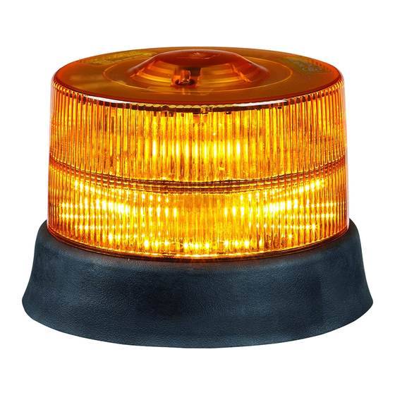
Installation and Maintenance Manual Overview of the LP800 Solaris Beacon The LP800 Solaris Beacon is an LED light source that provides a ® reliable signal with 14 flashing patterns. The LP800 Solaris Beacon has two Solaris reflectors with 15 powerful LEDs. The available colors are red, amber, or blue. -
Page 10: Product Specifications
Installation and Maintenance Manual Product Specifications Table 1 Specifications Input Voltage 10 Vdc to 30 Vdc Nominal 12.8 Vdc or 25.6 Vdc Input Current, Amber 2 A at 12.8 Vdc pulsed, 0.8 avg. (nominal) 1 A at 25.6 Vdc pulsed, 0.4 avg. Dimensions Height 4.67 inches (118.5 mm) -
Page 11: Figure 2 Vehicle Permanent Mount
Installation and Maintenance Manual 3. Place the supplied grommet in the hole drilled for the cable, and then feed the cable through the grommet. 4. Using the supplied hardware, mount the beacon to the mounting surface. Figure 2 Vehicle permanent mount Needed material (Not supplied) The following list the materials you need to install the light: •... -
Page 12: Figure 3 Lp800-Base
Installation and Maintenance Manual Figure 3 LP800-BASE Remove Install Needed material (Not supplied) The following list the materials you need to install the light: • Drill • 6 mm wrench • 13/64-inch Drill Bit (5 mm) • 25/64-inch Drill Bit (10 mm) LP800 Solaris Beacon Federal Signal www.fedsig.com... -
Page 13: Wiring The Mounted Beacon
Installation and Maintenance Manual Figure 4 LP800-BASE Kit Contents Wiring the Mounted Beacon REVERSE POLARITY/MISWIRING: Reverse polarity may damage the siren amplifier. To avoid damage to the siren/amplifier, ensure that the battery voltage is the same voltage as the rating of the light and that the correct polarity is observed. -
Page 14: Figure 5 Wiring The Single Beacon
Installation and Maintenance Manual Figure 5 Wiring the Single Beacon SINGLE BEACON +BATTERY WHITE -BATTERY BROWN +BATTERY +BATTERY GREEN +BATTERY +BATTERY PINK NO CONNECTION GRAY NO CONNECTION VIOLET Wiring the Dual Beacon Simultaneous Flash To wire the simultaneous beacon, do the following: 1. -
Page 15: Figure 6 Wiring The Simultaneous Flash
Installation and Maintenance Manual Figure 6 Wiring the Simultaneous Flash SIMULTANEOUS FLASH MASTER NO CONNECTION VIOLET +BATTERY WHITE +BATTERY -BATTERY BROWN PINK GREEN GRAY FOLLOWER +BATTERY +BATTERY +BATTERY WHITE GREEN PINK -BATTERY BROWN +BATTERY NO CONNECTION GRAY NO CONNECTION VIOLET Table 2 Wire Functions Wire Color Function (Switch Type) -
Page 16: Selecting A Flash Pattern
Installation and Maintenance Manual Selecting a Flash Pattern Selecting a flash pattern is optional and should be done during installation. The flash pattern is advanced by momentarily touching the green wire to positive voltage. See Table 3 for a list of flash patterns. -
Page 17: Cleaning The Lens
Installation and Maintenance Manual Cleaning the Lens Polycarbonate and ABS parts To extend the life of this product, Federal Signal recommends periodic cleaning using correct methods and cleaners. For general cleaning, do not use an abrasive cleaner or highly alkaline. Furthermore, do not scratch the plate with a rubber brush, razor blade, or with other sharpened instrument. - Page 18 Installation and Maintenance Manual 4. Align the three screw bosses in new dome with voids in the center of unit. 5. Reattach dome to base using the previously removed screws. 6. Remount the unit to surface and connect power. 7. Test unit for proper operation before returning vehicle to service.
-
Page 19: Figure 7 Template For Permanent Mounting
Installation and Maintenance Manual Figure 7 Template for Permanent Mounting Ø 5.12" [Ø 130 mm] 120° Ø 0.28" [Ø 7 mm] Ø 0.39" [Ø 10 mm] 1.00" [25 mm] LP800 Solaris Beacon Federal Signal www.fedsig.com... - Page 20 2645 Federal Signal Drive University Park, Illinois 60484 www.fedsig.com Customer Support Police/Fire-EMS: 800-264-3578 • +1 708 534-3400 Work Truck: 800-824-0254 • +1 708 534-3400 Technical Support 800-433-9132 • +1 708 534-3400...
Need help?
Do you have a question about the Solaris LP800 and is the answer not in the manual?
Questions and answers