Subscribe to Our Youtube Channel
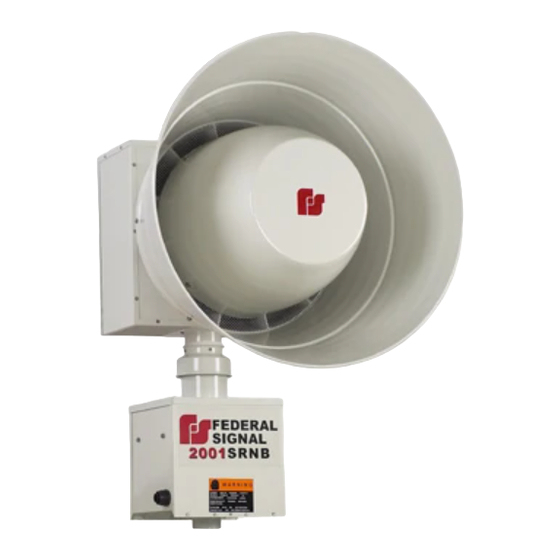
Summary of Contents for Federal Signal Corporation 2001SRNB
- Page 1 FEDERAL SIGNAL CORPORATION 2001SRNB ELECTRO-MECHANICAL SIREN INSTALLATION AND OPERATING INSTRUCTIONS Copyright 2004 Federal Signal Corporation 255232R 9/28/04...
- Page 2 IMPORTANT NOTICE Federal Signal reserves the right to make changes to devices and specifications detailed in the manual at any time in order to improve reliability, function or design. The information in this book has been carefully checked and is believed to be accurate; however, no responsibility is assumed for any inaccuracies.
- Page 3 SAFETY NOTICES People’s lives depend on your selection of suitable equipment and installation sites and your safe installation, service, and operation of our products. Federal Signal recommends the following publications from the Federal Emergency Management Agency for assistance with planning an outdoor warning system: 1.
- Page 4 SAFETY NOTICES People’s lives depend on your safe installation, service and operation of our products. It is important to read, understand and follow all instructions shipped with this product. In addition, listed below are some other important safety instructions and precautions you should follow: INSTALLATION &...
- Page 5 Limited Warranty The Signal Division, Federal Signal Corporation, warrants each new product to be free from defects in material and workmanship, under normal use and service, for a period of two years (one year for Informer, EAS, and Federal software products) on parts replacement and one year on labor from the date of delivery to the first user- purchaser.
- Page 6 WARNING Read and understand the information contained in this manual before attempting to install or service the siren. Pay careful attention to the following notices located on the equipment. NOTICES – EXTERNALLY PLACED.
-
Page 7: Table Of Contents
TABLE OF CONTENTS Paragraph Page SECTION I - CHARACTERISTICS Scope of this Manual ................1 General ....................1 Siren Description ..................1 Signal Description .................. 1 SECTION II - SPECIFICATIONS Specifications ..................2 SECTION III - INSTALLATION Siren Location ..................3 Siren Installation .................. -
Page 8: Section I - Characteristics
1-3. SIREN DESCRIPTION. The 2001SRNB siren is a single tone siren capable of producing a 128 dB sound Figure 1-2. Signal Characteristics. level at 100 feet for a minimum of 15... -
Page 9: Specifications
SECTION II SPECIFICATIONS Power Requirements* Siren Motor........... 48V (DC or full wave rectified AC) 100 amps. (nom.) Rotator Motor ..........48V (DC or full wave rectified AC) 1 amp. (nom.) Wiring Siren Motor........... 2 AWG Rotator Motor ..........14 AWG Motor Type Siren ............. -
Page 10: Section Iii - Installation
10dB. For electrical codes. example, the sound level at 100 feet (30.5m) from a 2001SRNB siren is 128dB. At 200 feet (61m), the level drops to 117dB; at 400 feet 3-1. SIREN LOCATION. -
Page 11: Siren Installation
2001SRNB siren is ground. It is attached to the pole by means of approximately 5800 feet. legs, as shown in figure 3-2. Wind speed and direction often affect the propagation sound from siren. Consequently, the direction of the prevailing... - Page 12 Lift the siren approximately 3-1/2 ft. with a To install a 2001SRNB on a flat roof or other crane or hoist. flat surface, proceed as follows:...
-
Page 13: Pre-Operation Checkout
WARNING The hoisting bracket does not have sufficient strength to support the combined weight of the siren and a platform. Therefore, do NOT lift the siren and platform together using the bracket as a lifting point. Hoist the siren to the installation site using the lift bracket as a lifting point (refer to WARNING above). - Page 14 D. After the installation is complete and control devices padlocked it has been established that the siren is discourage tampering and vandalism. operating properly, Federal recommends that Figure 3-4. Weight Distribution Mat Construction...
-
Page 15: General
Battery Box before inspecting or maintaining the siren. DANGER 4-2. INSPECTION. Service should be performed by Test the 2001SRNB siren for proper qualified personnel familiar with the operation at least once a month. A daily test siren, associated controls, at noon, curfew, or other selected time is power sources being used. -
Page 16: Corrective Maintenance
4-3. CORRECTIVE MAINTENANCE. 30 pounds (11 and 13kg.), the drive band requires adjustment. This section includes illustrations that may be helpful if the siren or rotator needs To adjust the drive band: repair. (a). Perform steps (a)., (b)., and (c). in paragraph 4-3.A.1. - Page 17 B. Collector Ring Brush Replacement. brush holder in the brush holder plate. (See figure 4-5). Open cover by removing screws and lockwashers. COVER WIRES WING NUT BRUSH HOLDER BRUSH 291304B Figure 4-5. Brush Holder Assy. Insert the replacement brush into 291302B the brush holder.
- Page 18 14. Replace the back panel. PLUG OPENING STAND-OFF D. Rotator Motor Replacement. Remove the two rotator housing panels (see figure 4-2). Replace rotator motor. Approximately a 1/64” gap between the teeth of the two gears is required to avoid binding. REMOVE BOLT(4) 291305B Re-tighten rotator motor bolts to a torque of...


Need help?
Do you have a question about the 2001SRNB and is the answer not in the manual?
Questions and answers