Federal Signal Corporation SmartSiren Platinum SSP3000B Installation And Maintenance Instructions Manual
Hide thumbs
Also See for SmartSiren Platinum SSP3000B:
- Quick connect manual (2 pages) ,
- Installation and maintenance instructions manual (64 pages)

Related Manuals for Federal Signal Corporation SmartSiren Platinum SSP3000B


Summary of Contents for Federal Signal Corporation SmartSiren Platinum SSP3000B
- Page 1 SmartSiren Platinum ® Model SSP2000B Model SSP3000B Installation and Maintenance Instructions 25500151 A3 0220 Printed in U.S.A. © Copyright 2015-2020 Federal Signal Corporation...
-
Page 2: Figure 1 All Trademarks Are Property Of Their Respective Owners
A copy of this limited warranty can also be obtained by written request to Federal Signal Corporation, 2645 Federal Signal Drive, University Park, IL 60484, email to info@fedsig.com or call +1 708-534-3400. -
Page 3: Table Of Contents
Contents Safety Messages for Installers and Operators .................7 Safety Messages to Installers of Sound/Light Systems ................7 Safety Messages to Operators of Sound/Light Systems ................ 9 An Overview of the SmartSiren Platinum................11 Siren, PA, and Speakers ...........................11 Light Bars and SignalMaster Control ......................11 Programmable Solid-State Auxiliary Relays....................11 Programmable Input Circuits .........................12 LED Indicators and Visual Diagnostics (Model SSP3000B Only) ............12... - Page 4 Mounting the Siren and Control Head ..................39 Mounting the Siren Amplifier/Relay Module .....................39 Mounting the Control Head ..........................40 Setting Control Head Options ....................42 Entering Program Mode ..........................42 Turning Off or On the 10-Second Notification Beep ..............42 Selecting Active-High Activation of Horn-Ring Transfer ............43 Selecting Active-High Activation of the Park Input Circuit ............
- Page 5 Figures Figure 1 All trademarks are property of their respective owners...........2 Figure 1 Dimensions of the control head ......................17 Figure 2 Dimensions of the siren amplifier/relay module ................17 Figure 3 Overview of Convergence Network Connections ..............19 Figure 4 Serial port locations ..........................21 Figure 5 Configurable activation options for 10 A relays with active-low capability ......22 Figure 6 Connection for 10 A solid-state auxiliary relays ................23 Figure 7 Connection for 2 A solid-state relays .....................24...
- Page 6 Figure 32 LED indicators and fuses on upper part of siren amplifier/relay module ......49 Figure 33 LED indicators on lower label of siren amplifier/relay module ..........50 Figure 34 LED programming indicators on the control head ..............50 Figure 35 Installing the control head labels....................51 Figure 36 Safety message card (left) and siren safety labels (right) ............52 Figure 37 Control head removed from mounting surface .................55 Figure 38 Control head removed from mounting brackets ..............55...
-
Page 7: Safety Messages For Installers And Operators
Safety Messages for Installers and Operators Safety Messages for Installers and Operators For your safety, read and understand this manual thoroughly before installing, operating, and servicing the SmartSiren Platinum siren amplifier/relay module. The safety messages presented in this section and throughout the manual are reminders to exercise extreme care at all times. - Page 8 Safety Messages for Installers and Operators During Installation • Do NOT get metal shavings inside the product. Metal shavings in the product can cause the system to fail. If drilling must be done near the unit, place an ESD approved cover over the unit to prevent metal shavings from entering the unit. Inspect the unit after mounting to be sure there are no shavings present in or near the unit.
-
Page 9: Safety Messages To Operators Of Sound/Light Systems
Safety Messages for Installers and Operators • If a vehicle seat is temporarily removed, verify with the vehicle manufacturer if the seat needs to be recalibrated for proper airbag deployment. • Locate the control head so the vehicle, controls, and microphone can be operated safely. - Page 10 Safety Messages for Installers and Operators stare directly into this lighting product at a close range or permanent damage to your eyesight may occur. • It is important that you fully understand how to safely operate this warning system before use. •...
-
Page 11: An Overview Of The Smartsiren Platinum
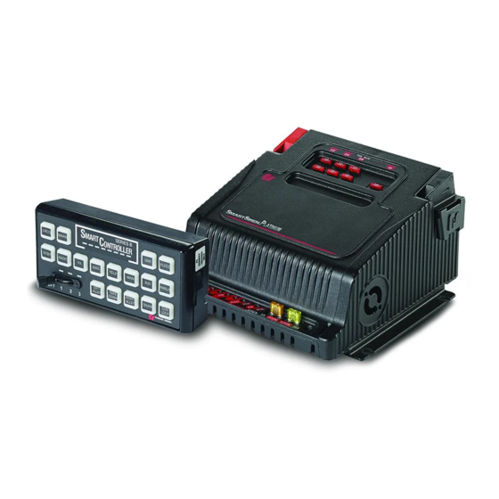
An Overview of the SmartSiren Platinum An Overview of the SmartSiren Platinum The SmartSiren Platinum siren amplifier/relay module is a full-featured, ® programmable electronic siren and light control system. State-of-the-art microprocessor technology is used to create a system with a small, compact control head and a siren amplifier/relay module that can be installed in the trunk, under the dashboard, or under the seat of any vehicle with a 12 V negative ground system. -
Page 12: Programmable Input Circuits
An Overview of the SmartSiren Platinum Programmable Input Circuits Both models of the siren amplifier/relay modules have connections for four relay input circuits. Relay inputs 1 and 2 are active-low inputs that activate a switch when pulled to ground. Relay inputs 3 and 4 are active-high inputs that activate a switch when pulled to 12 Vdc battery voltage. -
Page 13: Table 2 Siren Specifications
An Overview of the SmartSiren Platinum Table 2 Siren Specifications Speakers SSP2000B: one 100 W, 11-ohm speaker SSP3000B: one or two 100 W, 11-ohm speakers Operating Current (no lamps on) 9 A (nominal), (13.6 V battery, 11-ohm load at high power) Frequency Range 725 to 1 600 Hz... -
Page 14: Smartsiren Platinum Kit Contents
An Overview of the SmartSiren Platinum SmartSiren Platinum Kit Contents Tables 5 (Model SSP2000B) and 6 (SSP3000B) list the parts included with the SmartSiren Platinum kit. After unpacking the kit, examine it for damage that may have occurred in transit. If the product has been damaged, file a claim immediately with the carrier stating the extent of damage. -
Page 15: Table 6 Ssp3000B Kit Contents
An Overview of the SmartSiren Platinum Table 6 SSP3000B kit contents Qty. Description Part Number SSP3000B Control Head 853600632 SSP3000B Siren Amplifier/Relay Module 853600629 Cable Assembly, RS485, 25 ft 1751357-02 Cable Assembly, Control 17500307 Cable Assembly, Auxiliary Relay 1751541 Cable Assembly, RJ45 Ethernet Crossover 1751532 Cable Assembly, SignalMaster and Inputs... -
Page 16: Connecting The Convergence Network
Connecting the Convergence Network Connecting the Convergence Network Before permanently installing the SmartSiren Platinum system, plan all wire ® routings and select the mounting locations for the siren amplifier/relay module and control head. Read and understand all instructions included with related equipment before installing it. -
Page 17: Figure 1 Dimensions Of The Control Head
Connecting the Convergence Network module. Terminals for the ground and power connections are located on each side toward the rear. IMPORTANT: To maintain the reliability of the Model SSP3000B amplifier/relay module, which is cooled by a fan, ensure that there is enough room for the flow of air. -
Page 18: Overview Of The Convergence Network Connections
Connecting the Convergence Network Overview of the Convergence Network Connections The Convergence Network system has these types of connections via cables and locking connectors included with the kit. See Figure 4. Connections for the siren amplifier/relay module: • Three “plug and play” serial ports that communicate on the Federal Signal Convergence network with the control head, compatible light bars, and the Federal Signal Model 660100 Relay Module/Two-Channel Flasher. -
Page 19: Figure 3 Overview Of Convergence Network Connections
Connecting the Convergence Network Figure 3 Overview of Convergence Network Connections Installation and Maintenance Instructions Federal Signal www.fedsig.com... -
Page 20: Preparing For The Convergence Network Installaton
Connecting the Convergence Network Preparing for the Convergence Network Installation HIGH CURRENT ARCING: Do not connect this system to the vehicle battery until ALL other electrical connections are made and you have verified that no shorts exist. High current conductors can cause hazardous sparks or burning wire, resulting in electrical fires. -
Page 21: Connections For 10 A Auxiliary Relays
Connecting the Convergence Network To connect the devices: 1. Carefully route the cables from the network devices through the vehicle to the connectors on the siren amplifier/relay module. 2. To provide strain relief, secure the cables with installer-supplied clamps and hold-downs. -
Page 22: Figure 5 Configurable Activation Options For 10 A Relays With Active-Low Capability
Connecting the Convergence Network Table 7 Descriptions of configurable activation options for 10 A relays Configured Description Activation Active High The relay supplies +12 Vdc during the “on” state. Active Low The relay supplies ground during the “on” state. The relay is open during the “off” state, a condition similar to an open Open Off electromechanical relay. -
Page 23: Connections For Low-Current Auxiliary Relays
Connecting the Convergence Network Figure 6 Connection for 10 A solid-state auxiliary relays 10 A Relay Leads Ten 10 A Fuses Cable Assembly P/N 1751541 on Top of Siren for 10 A Relays 18 AWG 10 8 6 6 7 8 11 1 1 1 2 3 4 INPUT... -
Page 24: Connections For The Latitude Signalmaster
Connecting the Convergence Network Figure 7 Connection for 2 A solid-state relays Relay Leads Cable Assembly P/N 1751542-01 (SSP3000B) and P/N 1751542-NY (SSP2000B) 18 AWG 11 12 13 14 10 8 6 6 7 8 11 1 1 1 2 3 4 INPUT Connections for the Latitude SignalMaster ™... -
Page 25: Connections For Rear External Discrete Signalmaster (Ssp3000B Only)
Connecting the Convergence Network Connections for Rear External Discrete SignalMaster (SSP3000B Only) ™ Cable assembly 1751542-01 includes 18-inch, 20 AWG wires for six-head and eight- head SignalMaster light bars that are wired discretely. These directional warning lights are standalone light bars, rather than part of a full-featured, serial-controlled light bar, with separate wires for each light head. -
Page 26: Connections For Relay Inputs 1 To 4
Connecting the Convergence Network Connections for Relay Inputs 1 to 4 Cable assemblies P/N 1751542-01 and P/N 1751542-NY include 18-inch, 20 AWG wires for four relay circuit inputs. Figure 9 shows the connectors for the four input leads on the back of the amplifier/ relay module. Inputs 1 to 4 are most commonly used for circuits that send a signal to the SSP3000B system when a condition in the vehicle changes. -
Page 27: Connections For The Ambient Light Sensor
Connecting the Convergence Network Connections for the Ambient Light Sensor The SSP3000B and SSP2000B both support Federal Signal light bars equipped with an ambient light sensor. The software uses Input 1 to activate functions when the light bar senses low light. No extra connections are needed to support this feature. -
Page 28: Speaker Connections (Cable Assembly P/N 17500307)
Connecting the Convergence Network Speaker Connections (Cable Assembly P/N 17500307) The SSP2000B siren amplifier operates with one 11 ohm impedance, 100 W speaker. The SSP3000B is designed to operate with one or two 11 ohm impedance, 100 W speakers. Software-configurable options include a variety of siren tones, horn ring transfer, slide switch operation, and siren activation or siren mute. -
Page 29: Horn Ring Transfer (Cable Assembly 17500307)
Connecting the Convergence Network Horn Ring Transfer (Cable Assembly 17500307) The default setting for the slide switch transfers the horn-ring activation of the siren in Slide Switch 2 and 3. In Slide Switch 2, a press of the horn button activates the Manual tone. -
Page 30: Figure 13 Connections For Horn-Ring Transfer Circuit
Connecting the Convergence Network Figure 13 Connections for horn-ring transfer circuit +12V 10 8 6 6 7 8 11 1 1 1 2 3 4 SERIAL PORTS PARK INPUT DO NOT EXCEED 5 AMPS MAXIMUM ON HORN RING CIRCUIT. SEE INSTALLATION INSTRUCTIONS White/Yellow 18 Awg To Horn Ring Side of Cut Wire... -
Page 31: Radio Rebroadcast (Cable Assembly 17500307)
Connecting the Convergence Network Radio Rebroadcast (Cable Assembly 17500307) To allow incoming two-way radio messages to be amplified by the siren amplifier/ relay module and rebroadcast over the siren speakers, connect the brown 18 AWG two-conductor zip-cord across the speaker of the two-way radio. See Figure 14. Insulate spliced leads with twist-on wire connectors. -
Page 32: Connecting The Control Head
Connecting the Convergence Network Connecting the Control Head In addition to the connection through the 25-foot Convergence Network cable, the control head has: • Connections for four active-low input circuits that activate when pulled to ground (17500308) • Connections to the siren for battery ground (–GND) and +12 Vdc switched by ignition or battery +12 Vdc for ignition timers (17500308) •... -
Page 33: Connecting Ignition Power To The Control Head (Without Ignition Timer)
Connecting the Convergence Network Each input circuit can be programmed to activate with an installer-supplied switch having a current capacity of 100 mA , with the SSP3000B control head, or with the two-way switches on the steering wheel of the Ford Police Interceptor. For the location of the vehicle 14-way connector for the ground-sourcing outputs, refer to the Ford Police Interceptor Modifier Manual. -
Page 34: Connecting The Federal Signal Microphone (P/N 258B8577-03)
Connecting the Convergence Network To connect the control head to ignition power: 1. Use a multimeter to determine which source provides power when the vehicle key is in the ignition position. 2. Connect the yellow lead from the control head to the switched side of the vehicle ignition harness. -
Page 35: Connecting The Siren To The Battery
Connecting the Convergence Network Connecting the Siren to the Battery This section has instructions for making the power connections from the SmartSiren to the battery. Required are an installer-supplied in-line fuse and wiring ® of an amperage capacity sufficient to handle the total vehicle electrical loads. EXPLOSION HAZARD: To avoid a battery explosion, always disconnect the negative battery cable first and reconnect it last. -
Page 36: Figure 17 Negative Ground Connection For The Control Head
Connecting the Convergence Network 4. Reconnect the positive cable to the vehicle battery and tighten the clamp. 5. Reconnect the negative cable to the vehicle battery and tighten the clamp. Figure 17 Negative ground connection for the control head Terminal 1/4"-20, SS Ext. -
Page 37: Setting The Gain For Radio Rebroadcast And Pa
Setting the Gain for Radio Rebroadcast and PA Setting the Gain for Radio Rebroadcast and PA The radio rebroadcast feature allows incoming two-way radio messages to be amplified by the siren amplifier/relay module and rebroadcast over the siren speakers of the SSP3000B system. The feature overrides all sirens functions. Button 7 is programmed as the default control for radio rebroadcast. -
Page 38: Setting The Gain For Public Address (Microphone Volume)
Setting the Gain for Radio Rebroadcast and PA Figure 19 Gain control for radio rebroadcast (siren amplifier/relay module) Radio Rebroadcast Gain Control Setting the Gain for Public Address (Microphone Volume) The PA gain control port on the front of the siren amplifier is for select models that require the microphone to be connected to the siren. -
Page 39: Mounting The Siren And Control Head
Mounting the Siren and Control Head Mounting the Siren and Control Head The next step in the installation after wiring and connecting the SSP3000B/ SSP2000B system is to permanently mount the siren amplifier/relay module and control head in the vehicle. Verify that the mounting locations you selected earlier are safe for installing these components. -
Page 40: Mounting The Control Head
Mounting the Siren and Control Head Figure 22 Slots for mounting hardware Mounting Slots (4 Places) 7.49 in (19.03 cm) 4.50 in (11.43 cm) Installer-Supplied #10-32 Mounting Hardware Required 1.05 in (2.66 cm) 7.94 in (20.17 cm) 290A7560 2. Tap and drill the center of the four mounting holes. 3. -
Page 41: Figure 23 Bracket Attached To Back Of Control Head
Mounting the Siren and Control Head Figure 23 Bracket attached to back of control head Control Pad Note: Use one of the three sets of holes in the pivot bracket to best position the control pad. #6 Split Lock Washer (2) #6-32 X 1/4"... -
Page 42: Setting Control Head Options
Setting Control Head Options Setting Control Head Options The SmartSiren Platinum control head has these configurable features: • A notification beep that sounds every ten seconds when one or more functions or devices in the system, such as a light bar, is activated. The default setting is “on.”... -
Page 43: Selecting Active-High Activation Of Horn-Ring Transfer
Setting Control Head Options Figure 25 LEDs and buttons associated with Program Mode settings Indicates that the Ethernet is on for system configuration and the control pad is in Program Mode. (See the Configuration Software Manual P/N 2562418.) Indicates that the control pad is ready to be reset to the factory default configuration Indicates the button LEDs are selected for DIM or OFF Indicates that the Park Disable circuit is selected for active high (ON) or active low (OFF) activation... -
Page 44: Dimming Or Turning Off The Button Leds
Setting Control Head Options Selecting Active-High Activation of the Park Input Circuit For instructions on connecting the control head to the Park Input circuit, see “Park Input (Cable Assembly 1751542-01 or 1752542-NY)” on page 27. The default setting is active-low. To select the active-high activation of the Park Input feature: 1. -
Page 45: Resetting The Control Head To The Factory Default Configuration
Setting Control Head Options Figure 26 Keep-Alive Timeout durations Resetting the Control Head to the Factory Default Configuration To reset the operation and control of network devices to the factory default: 1. While in Program Mode, press Button 7. See Figure 25 on page 43. 2. -
Page 46: Testing The Convergence Network Installation
Testing the Convergence Network Installation Testing the Convergence Network Installation SOUND HAZARD: All effective sirens and horns produce loud sounds (120 dB) that may cause permanent hearing loss. Always minimize your exposure to siren sounds and wear hearing protection. Do not sound the siren indoors or in enclosed areas where you and others will be exposed to the sound. -
Page 47: Figure 27 Ssp2000B Default Configuration For Control Head
Testing the Convergence Network Installation Figure 27 SSP2000B default configuration for control head Signal Warn Button 14 Button 15 SSP2000B Master Button Control: SignalMaster Button Control: ™ Push On/Off Rear Light Bar Push On/Off Rear Light Bar Rear Light Left, Right, Light Bar: Step-Through Cutoff... -
Page 48: Figure 29 Ssp3000B Default Configuration For Control Head
Testing the Convergence Network Installation Figure 29 SSP3000B default configuration for control head Signal Warn Button 14 Button 15 SSP3000B Master Button Control: Step-Through Button Control: Push On/Off Rear Warning Push On/Off Light Bar Patterns Rear Light Light Bar: 1 to 4 Cutoff 8-Head Dimming... -
Page 49: Figure 31 Default Configuration For Steering Wheel Switches Wired To Control Head
Testing the Convergence Network Installation Figure 31 Default configuration for steering wheel switches wired to control head Slide Switch 3 Slide Switch 1 Button 2 Slide Switch 2 Figure 32 LED indicators and fuses on upper part of siren amplifier/relay module AUX 11–14: LED flashes when the output is on for a 2 A auxiliary solid-state relay. -
Page 50: Figure 33 Led Indicators On Lower Label Of Siren Amplifier/Relay Module
Testing the Convergence Network Installation Figure 33 LED indicators on lower label of siren amplifier/relay module 290A7568 ON: LED glows when the network has power. RAD VOL: Screw for adjusting the factory-set radio volume. PA VOL: Screw for adjusing the factory-set public address volume. -
Page 51: Control Head Legends And Safety Messages
Control Head Legends and Safety Messages Control Head Legends and Safety Messages To complete the installation, the SmartSiren kit includes: • A scored sheet of replaceable keyhead legends that identify the functions of the control head buttons (part no. 181460). Before installing the legends, configure the operation of the control head with the Convergence Configuration Software (see the Convergence Network Software Configuration Manual, part no. -
Page 52: Applying The Siren Safety Labels In The Vehicle
Control Head Legends and Safety Messages Applying the Siren Safety Labels in the Vehicle The kit includes a sheet of two labels with siren safety messages (part no. 1612339). See Figure 36. These labels must be installed in the vehicle in which the system is installed. -
Page 53: Safety Messages To Personnel Servicing Federal Signal Electronic Sirens
Safety Messages to Personnel Servicing Federal Signal Electronic Sirens Safety Messages to Personnel Servicing Federal Signal Electronic Sirens The people’s lives depend on your proper servicing of Federal Signal products. It is important to read and follow all instructions shipped with the products. |In addition, listed below are some other safety instructions and precautions you should follow: •... -
Page 54: Servicing The Convergence Network System
Servicing the Convergence Network System Servicing the Convergence Network System Federal Signal recommends that the siren amplifier/relay module and control head be returned to your local distributor or Federal Signal for service. External components such as cabling, fuses, and the red and black insulators are available as replacement parts. -
Page 55: Figure 37 Control Head Removed From Mounting Surface
Servicing the Convergence Network System Figure 37 Control head removed from mounting surface 1/4" Lockwasher, Ext. Tooth (2) 1/4-20 X 3/4" Hinge Screw, Hex Head (2) 290A7569 Figure 38 Control head removed from mounting brackets #6 Split Lockwasher (2) #6-32 X 1/4" Screw, Phil. -
Page 56: Replacing The Slide Switch In The Control Head
Servicing the Convergence Network System Replacing the Slide Switch in the Control Head To replace the slide switch: 1. Remove and retain the four Phillips #6-32 x 5/16” screws securing the control head base to the control head assembly. See Figure 39. 2. -
Page 57: Reinstalling The Control Head
Servicing the Convergence Network System Reinstalling the Control Head To reinstall the control head in the vehicle: 1. Reconnect the cables and wiring to the control head. 2. Secure the rear mounting bracket to the control head base with the two Phillips #6-32 by 1/4-inch screws. -
Page 58: Replacing A Terminal Insulator
Servicing the Convergence Network System properly seated. Figure 40 External parts assembly (SSP3000B shown) 1/4"-20, SS Insulator, Fuse, 10 A, Mini Blade, Keps® Nut (2) LED Indicator, Red Fuse, 20 A, Mini Blade, LED Indicator, Yellow 1/4"-20, SS, Ext. Tooth Lock Washer (4) 0.266"... -
Page 59: Reinstalling The Siren Amplifier/Relay Module
4. Reinstall the siren amplifier/relay module in the vehicle with the installer- supplied #10-32 mounting hardware. Getting Technical Support For technical support and service, please contact: Service Department Federal Signal Corporation Phone: 1-800-433-9132 Email: empserviceinfo@fedsig.com www.fedsig.com Getting Repair Service The Federal Signal factory provides technical assistance with any problems that cannot be handled locally. -
Page 60: Ordering Replacement Parts
Ordering Replacement Parts Ordering Replacement Parts The cover is available as a service part only. To order replacement parts, call Customer Support at 1-800-264-3578, 7 a.m. to 5 p.m., Monday through Friday (CT) or contact your nearest distributor. Table 10 Replacement parts Description Part Number Cable Assembly, RS485, 25 ft...
Need help?
Do you have a question about the SmartSiren Platinum SSP3000B and is the answer not in the manual?
Questions and answers