Craftex CX Series Manual
6” jointer 1hp
Hide thumbs
Also See for CX Series:
- User manual (49 pages) ,
- Manual (42 pages) ,
- Owner's manual (35 pages)
Table of Contents
Advertisement
Quick Links
Advertisement
Table of Contents

Related Manuals for Craftex CX Series


Summary of Contents for Craftex CX Series
- Page 1 MODEL CX06Z 6” JOINTER 1HP Ver. 1.0...
-
Page 2: Table Of Contents
TABLE OF CONTENTS General Safety Instructions ..................3 Machine Specifications ................... 4 Power Supply ......................5 Circuit Requirements ....................6 Plug and Grounding Requirements ................. 6 Use with Extension Cords ..................7 Setup & Inventory ....................8 Mounting the Jointer ....................9 Components &... -
Page 3: General Safety Instructions
GENERAL SAFETY INSTRUCTIONS Extreme caution should be used when operating all power tools. Know your power tool, be familiar with its operation, read through the owner’s manual and practice safe usage procedures at all times ALWAYS read and understand the user manual before operating the router bits, shaper heads, blades, knives machine. -
Page 4: Machine Specifications
CX06Z MACHINE SPECIFICATIONS Table Size…………………………………………………………………………………………………6” W x 46” L Table Height......................32‐1/2” Overall length………………………………………………………………………………………………………..46” Overall Width………………………………………………………………………………………………….27‐1/2” Shipping weight………………………………………………………………………………………………….80 kg Net Weight………………………….………….………………………………………………………………….74 kg Box 1 Size……………………………………………………………………………………….48‐1/2” x 21” x15” Box 2 Size…………………………………………………………………………20‐1/2” x 15‐3/4” x 28‐3/4” Foot Print……………………………………………………………………………………………….18” x 13‐1/2” Maximum Depth of cut……………………………………………………………………………….………..1/8” Maximum Width of Cut………………………..…………………………………....……………………6” Cutterhead Diameter…………………………………………………………………………………………2‐1/2” Cutterhead Speed…………………………………….………………………………………………….4800 RPM Cuts Per Minute………………………………………………………………………………………………..14,400 Tables………………………………………Independently Adjustable, Precision Ground Cast Iron Stand………………………………………………………………………………………………….Preformed Steel Ways………………………………………………………………………………………..Dovetailed, Adjustable Fence Assembly……………….…………………………………………………………………………….Cast Iron Body Assembly...……………..…………………………………..……………………………..…………Cast iron Base………………………….…………………………………………………………….One Piece Steel Cabinet Cutterhead………….…………………………………………..3 Knife Slots c/w jack Screws & springs Guard………………………………………….…………………………………………………………Die Cast Metal Bearings….……………………………………………………………….Sealed & Permanently Lubricated Motor:Type TEFC………………………………………………………….TEFC Capacitor Start Induction Horsepower………………………………………………………………………………………………………….1 HP Phase / Voltage…………….…………………………………………………………………….Single – 110Volt Amps……………………….…………………………………………………………………………………………….14A Cycle / RPM…………………………………………………………………………………60 Hertz / 3450 RPM Power Transfer…….……………………………………………………………………………………V‐Belt Drive Bearings…………….…………………………………………………….Sealed & Lubricated Ball Bearings Fence…………..………………………………Center Mounted, Positive Stops at 45 Deg & 90 Deg Table Movement……………………..…………Hand wheel/Lever and infeed & Outfeed tables ... -
Page 5: Power Supply
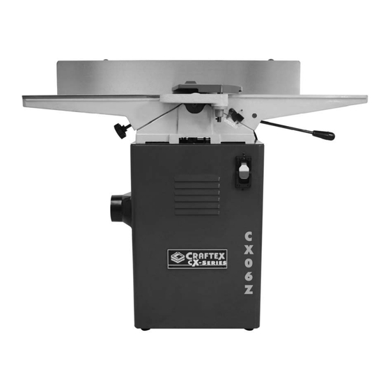
Specifications, while deemed accurate, are not guaranteed. Identification A. Outfeed table B. Fence C. Cutterhead Guard D. Fence Lock E. Fence Adjustment Knob F. Fence Tilt Handle G. Switch H. Infeed Table I. Infeed Table Lever J.Depth Scale K. Dust Port L. Outfeed Table Handwheel POWER SUPPLY by a licensed electrician. Use of a licensed AVAILABILITY OF POWER electrician will minimize the risks of fire, electrocution, damage to equipment, and Before Installation of this machine you will... -
Page 6: Circuit Requirements
CIRCUIT REQUIREMENTS FOR CX06Z JOINTER The CX06Z has been prewired at the factory for operation on an electrical circuit that has a verified ground and meets the following requirements: Voltage: 110V – 120V FULL LOAD CURRENT RATING Cycle: 60Hertz Phase: Single This is the amount of Amps a machine Circuit Breaker Size:... -
Page 7: Use With Extension Cords
reduce the chances of electrical shock by NOTE: providing a path of least resistance for the If ever you notice damage or wear to either electric current to travel through. For this the cord or plug disconnect it immediately reason the CX06Z comes with a cord from the power supply and have it equipped with a grounding wire that leads replaced by a licensed electrician or... -
Page 8: Setup & Inventory
Customer Service or your local Busy Bee SETUP Outlet. Save all containers and packing materials for WARNING! possible inspection by the carrier or its agent. This machine presents a serious injury hazard When completely satisfied with your shipment to untrained users. Read through this entire you should inventory the contents. manual to become familiar with controls and operations before starting the machine! INVENTORY WARNING! Check for the following items packed in the Always ... -
Page 9: Mounting The Jointer
Hardware & Tools Qty Mounting the Jointer Wrenches 8/10mm & 12/14mm 1 each Components & Hardware Required: Hex Keys 2.5, 3, 4, 6, & 8mm 1 each Qty Cap Screws M10‐1.5 x 20 3 Table Assembly 1 Cap Screws M10‐1.5 x 25 2 Cabinet 1 Hex Bolts M10‐1.5 x 55 Cap Screws M10‐1.5 x 20 ... -
Page 10: Components & Hardware Required
4. With the 8mm Hex Key, secure the jointer to the cabinet with the M10‐1.5 x 20 cap screws, flat washers and lock washers. Note: Reach through the dust vent for access to the forward mounting hole as in (Fig. D) Figure E 3. Carefully allow the motor to slide downward, tensioning the V‐belt with the weight of the motor. 4. Looking from the top, sight down the V‐belt and pulleys and check that the pulleys ... -
Page 11: Carriage Mounting Bracket
2. Tighten the carriage mounting bracket to the jointer table with the cap screws, lock washers & flat washers supplied. (Fig. H) Figure F Carriage Mounting Bracket Figure H Components & Hardware Required: Qty Assembling the Fence Carriage Carriage Mounting Bracket 1 Cap Screws M8‐1.25 x 60 4 Lock Washers 8mm ... -
Page 12: Assembling The Fence
2. Thread the fence tilting handle into the fence assembly as in (Fig. K) Figure I Assembling the Fence Figure K Components & Hardware Required: Qty Cutterhead Guard Fence Assembly 1 Cap Screws M8‐1.25 x 25 2 CAUTION! Lock Washers 8mm 2 The cutterhead guard is a critical safety Flat Washers ... -
Page 13: Dust Port Installation
Figure L Figure N 2. Wind the torsion spring knob back counterclockwise a half turn, then slide Dust Port Installation the guard shaft into the casting as shown in (Fig. M) ensuring the slot on Components & Hardware Required: the cutterhead guard shaft fits over ... -
Page 14: Outfeed Table Height Setting
Outfeed Table Height Setting The outfeed table needs to be at the same height as the cutterhead knives when at top dead centre. This adjustment is preset at the factory but should be checked before you use your jointer. This adjustment must also be made whenever you change the cutterhead knives. 1. Place a straightedge on the outfeed table and extend it over the cutterhead. Figure O 2. Rotate the cutterhead until one of the knives is at top dead center (TDC), as Table Controls Installation shown in (Fig.Q) Components & Hardware Required: Qty Outfeed Table Handle 1 Infeed Table Lever 1 Phillips Head Screws M5‐.8 x 15 1 Flat Washers 5mm 1 ... -
Page 15: Test Run & Recommended Adjustments
4. Lock the outfeed table suspect any problems and refer to the trouble shooting section of this manual before re‐ starting. Recommended Adjustments Your machine has been factory preset so very little if any re‐adjustments should be necessary, however because of any unforeseen problems in the shipping process ... -
Page 16: Stock Inspection
Note: 2. Use the infeed table lever to raise or For your own safety and experience we lower the table (Fig.U) recommend that you seek additional training outside of this manual. Books and magazines 3. Set the infeed table to the desired are also good source materials to gain more depth of cut on the depth of cut scale experience. and lock the table in position Infeed Table Adjustment Note: Adjust the infeed table stops to return the Before any cut the proper infeed table table height to the same height every by adjustment must be made to safely and loosening ... - Page 17 CAUTION: Your workpiece must exceed the minimum dimensions of stock shown in (Fig. W & X) when edge jointing or surface planing. Stock of smaller dimensions may break or kickback during operations. Figure V Your jointer is designed only to cut ...
-
Page 18: Squaring Stock & Surface Planing
2. Surface plane on a thickness planer – The opposite face of the workpiece is surface planed flat with a thickness planer. Figure Y Edge joint on the jointer ‐ The concave edge of the workpiece is jointed flat ... -
Page 19: Edge Jointing
workpiece against the table and the fence. (Fig.Y) Note: When your leading hand gets within 4” of the cutterhead lift it up and over the cutterhead and place the push block on the portion of the workpiece that is now on the outfeed table. Now, focus your pressure on the outfeed end of ... -
Page 20: Bevel Cutting
Note: 1. Make sure you have inspected your When your leading hand gets within 4” workpiece for knots and or foreign of the cutterhead. Lift it up and over objects before passing it through the the cutterhead and place it on the jointer. portion of the workpiece that is now ... -
Page 21: Rabbet Cutting
Note: if a second edge is jointed it will most likely not be parallel with the 3. Remove the cutterhead guard. first. 4. Make sure your fence is moved Rabbet Cutting forward, so the amount of infeed/Outfeed table exposed is the same size as your rabbet. Ensure the When ... -
Page 22: Maintenance & Inspecting The Knives
accumulated dust, moisture, and built up resin. 2. Remove the cutterhead guard or block it out of the way. 1. Vacuum all dust on and around the machine after daily use. 3. Lower the infeed table to the ½” scale mark. 2. Wipe down the tables and unpainted surfaces with a metal protectant. 4. Place the knife jig on the cutterhead, ... -
Page 23: Disconnect The Power From The Power Source
jig is supplied with your jointer to allow you to Note: set all the knives to the correct height. There are two adjustment methods you can use to accomplish knife This jointer comes with both jack screws and settings. You may use one or the other, springs, allowing you two options for jack screws or springs. If you decide to cutterhead adjustments (Fig.GG) Note: Only use the jack screws, remove the one ... -
Page 24: Depth Scale Calibration
Repeat steps 5 – 7 with the rest of the Setting the Fence Stops knives. Fence stops are adjustable nuts and bolts to 8. Rotate the cutterhead to the first knife simplify the task of adjusting the fence to 45 you started with, and then slightly deg. inward, 90 deg., and 45 deg. outward tighten all the gib bolts. Start at the (135 deg.) ... -
Page 25: Setting The Fence Stops
Setting the 90 deg. Fence Stop 2. Using a sliding bevel adjusted to 135 deg., adjust the fence to the 135 deg. 1. Flip the 90 deg. swing stop into the (45 deg. outward) position. position as in (Fig.MM) Figure MM Figure OO 2. With a 90 deg. square, adjust the fence Loosen ... -
Page 26: Electrical Components & Service
2. With a 3mm hex key, evenly tighten the gib setscrews a small amount, then check the table by moving it up and down. Adjust these setscrews as needed until the friction of the table movement is balanced between minimal play and ease of movement. ... - Page 27 4) Symptom SERVICE Motor overheats Motor & Machine Operation Possible Cause 1) Symptom 1. Motor overloaded during operation. Motor will not start 2. Air circulation of the motor restricted. Possible Cause Possible Solution 1. Emergency stop button depressed. 1. Reduce load on motor; take lighter cuts. 2. Low voltage. 2. Clean out motor to provide normal air 3. Open circuit in motor or loose connection circulation. Possible Solution 5) Symptom 1. Lift the cover on the emergency stop Motor stalls or shuts off during cut button to allow it to pop out. 2. Check power line for proper voltage. Possible Cause 3. Inspect all led connections on motor for 1. Motor overloaded during operation. loose or open connections. 2. Short circuit in motor or loose connections. 3. Circuit breaker tripped. 2) Symptom Fuses or circuit breakers blow ...
- Page 28 Possible Cause Possible Solution 1. Pulley setscrews or keys are missing or 1. Re‐adjust the table gibs. loose. 2. Motor fan is hitting the cover. Cutting 3. V‐belts are damaged. 3) Symptom Possible Solution Excessive snipe (gouge in the end of the board 1. Inspect keys and setscrews. Replace or that is uneven with the rest of the cut) tighten as necessary. 2. Adjust fan cover mounting position, tighten Possible Cause fan, or shim fan cover. 1. Outfeed table is set too low. 3. Replace V‐belts. 2. Operator pushing down on the end of the workpiece. 8) Symptom Vibration when running or cutting Possible Solution 1. Align outfeed table with cutterhead knife at Possible Cause top dead centre. 1. Loose or damaged blade. 2. Reduce/eliminate downward pressure on 2. Damaged V‐belt. the end of that workpiece. 3. Worn cutterhead bearings ...
- Page 29 3. Slow the feed rate down. Symptom 4. Take a smaller depth of cut. (Always reduce Board edge is convex or concave after jointing cutting depth when surface planing or working with hard woods) Possible Cause 1. Board not held with even pressure on Symptom infeed and outfeed table during cut. Fuzzy grain 2. Board started too uneven. 3. Board has excessive bow or twist along its Possible Cause length. 1. Wood may have high moisture content. Or 4. Insufficient number of passes. surface wetness. 2. Dull knives. Possible Solution 1. Hold board with even pressure as it moves Possible Solution over the cutterhead. 1. Check moisture content and allow to dry, if 2. Take partial cuts to remove the extreme moisture is too high. high spots before doing a complete pass. 2. Replace knives. 3. Surface plane one face to be sure there is a good surface to put against the fence. Symptom 4. It may take 3 to 5 passes to achieve a Long lines or ridges that run along the length perfect edge, depending on the starting of the board ...
- Page 30 TABLE PARTS BREAKDOWN ...
- Page 31 TABLE PARTS LIST Item Part # Description Item Part # Description 1 PCX06Z01 GIB 45 PCX06Z45 PLATE 2 PCX06Z02 KNIVES 46 PCX06Z46 TORSION SPRING 3 PCX06Z03 GIB SCREW 1/4‐28 X 9/32 47 PCX06Z47 CLIP 4 PCX06Z04 PULLEY 48 PCX06Z48 RETAINER 5 ...
- Page 32 FENCE PARTS BREAKDOWN...
- Page 33 FENCE PARTS LIST Item Part # Description Item Part # Description 88 PCX06Z88 FENCE 112 PCX06Z112 SCREW ‐ CAP M6‐1.0 X 20 89 PCX06Z89 LEVER ROD 113 PCX06Z113 SCREW ‐ PHLP HD M6‐1.0 X 12 90 PCX06Z90 BALL KNOB 114 PCX06Z114 WASHER ‐ LOCK 8MM 91 PCX06Z91 HANDLE HUB 115 PCX06Z115 GUARD 92 PCX06Z92 WASHER ‐ FLAT 10MM 116 PCX06Z116 ...
- Page 34 BASE PARTS BREAKDOWN ...
- Page 35 BASE PARTS LIST PCX06Z206 SCREW ‐ CAP M8‐1.25 X 65 Item Part # Description PCX06Z207 STRAIN RELIEF 231 PCX06Z231 SCREW ‐ TAP M4 X 8 PCX06Z208 NUT ‐ HEX 3/8‐16 232 PCX06Z232 SCREW ‐ TAP M4 X 8 PCX06Z209 ADJUSTING SCREW PCX06Z210 NUT ‐ HEX 5/16‐18 PCX06Z211 WASHER ‐ FLAT 10MM PCX06Z212 MOTOR BRACKET PCX06Z213 DUST CHUTE ...
-
Page 36: Warranty
RETURNS, REPAIRS AND REPLACEMENTS To return, repair, or replace a Craftex product, you must visit the appropriate Busy Bee Tools showroom or call 1-800-461-BUSY. Craftex is a brand of equipment that is exclusive to Busy Bee Tools. For replacement parts directly from Busy Bee Tools, for this machine, please call 1-800-461-BUSY (2879), and have your credit card and part number handy.
Need help?
Do you have a question about the CX Series and is the answer not in the manual?
Questions and answers