Craftex CX Series User Manual

Craftex CX Series User Manual

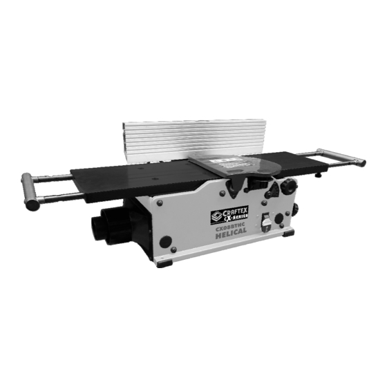
8" bench top jointer with helical cutterhead
Hide thumbs Also See for CX Series:

Advertisement

MODEL CX08BTHC
8" BENCH TOP JOINTER WITH
HELICAL CUTTERHEAD
USER MANUAL
VERSION 1
 
1

Advertisement

Table of Contents
loading

Summary of Contents for Craftex CX Series

  • Page 1 MODEL CX08BTHC 8” BENCH TOP JOINTER WITH HELICAL CUTTERHEAD USER MANUAL VERSION 1  ...
  • Page 2: Table Of Contents

    TABLE OF CONTENTS General Safety Instructions ..................3 General Safety Rules ....................4 Motor Specifications & Electrical Requirements ............5 Power Supply ......................6 Plug and Grounding Requirements ................7 Unpacking ......................... 8 Assembly ........................9 Cutter Head Guard ....................11 Switch Assembly and Fence Adjustments ..............
  • Page 3: General Safety Instructions

    GENERAL SAFETY INSTRUCTIONS Extreme caution should be used when operating all power tools. Know your power tool, be familiar with its operation, read through the owner’s manual and practice safe usage procedures at all times.  ALWAYS read and understand the ...
  • Page 4 JOINTER SPECIFIC SAFETY INSTRUCTIONS  ALWAYS make sure the machine is  ALWAYS inspect your stock for level before operating. knots or imbedded debris before feeding over the cutter head.  IF YOU ARE NOT FAMILIAR with  NEVER back your work-piece into the operations of a jointer, you should obtain the advice and/or the spinning cutter head.
  • Page 5 SPECIFICATIONS  Cutterhead  speed  RPM:…………………………………………………………………………………………………12,000      Motor  RPM:…………………………………………………………………………………………19000+/‐10%  (No  Load)      Cutterhead  diameter:………………………………………………………………………………………………………………2”      Max width of cut:…………………………………………………………………………………………………………………….8"    Max  depth  of  cut:……………………………………………………………………………………………………………….1/8"      Cutter inserts qty:……………………………………………………………………………………………………………………16    Motor  power  input:……………………………………………………………..120  V,  60  Hz,  AC  Only,  10  Amp      Fence Size Overall:……………………………………………………………………………………………..4‐3/8” x 19‐5/8”   Tables (Overall measurements):…………………………………………………………………………………..8” x 33.5”   Tables (Overall measurements incl. extension  support):……………………………………………….8”  x  51”    Shipping Weight:…………………………………………………………………………………………………………………59lbs   Net Weight:…………………………………………………………………………………………………………………………49lbs   Shipping Dimensions:………………………………………………………………………...37” L x 16” W x 12” H   Machine  Length:……………………………………………………………………………………………………………………51”    Machine Depth:……………………………………………………………………………………………………………………….8”   Machine Height:………………………………………………………………………………………………………………….13 ¼”     ...
  • Page 6: Power Supply

    POWER SUPPLY AVAILABILITY OF POWER WARNING!!! Before Installation of this machine you will Do not connect machine to power need to consider the proximity of your before setup been fully power supply circuit. If available circuits do completed to avoid risk of personal not meet the requirements for this machine injury or property damage.
  • Page 7: Plug And Grounding Requirements

    replacement of the power cord is necessary PLUG AND GROUNDING in the future please consult a licensed REQUIREMENTS electrician. This machine must be grounded so that in the event of certain malfunctions it will NOTE: reduce the chances of electrical shock by If ever you notice damage or ware to either providing a path of lesser resistance for the the cord or plug disconnect it immediately...
  • Page 8: Unpacking

    UNPACKING   Always  inspect  and  check  the  shipping  NOTE  carton and machine for damage before you  Some parts may have been already installed  begin  the  unpacking  process.  Carefully  on your machine while it was at the factory.  remove  all  of  the  packing  materials,  parts,  Go  through  the  manual  thoroughly  before  and  machine  from  it’s  shipping  carton.  calling customer service.  Check  for  any  packing  materials  around   ...
  • Page 9: Assembly

      A. Jointer  2. Take the Square nut (C) and place in to  B. Sliding Fence Bracket  the groove of the fence. Now assemble  C. Fence Bracket  the sliding fence bracket (A). See Figure  D. 2.5mm Hex Wrench  B.  E. 4mm Hex Wrench  F. Torx Wrench  G. Fence  H. Safety Switch Insert  I. Push Blocks  J. Soc Button Head Screw  K. Flat Washer  L. Special Nut  M. Tilt lock lever Assembly  N. Dust Collection Adapter    Figure B  ASSEMBLY   3. Adjust  the  sliding  fence  bracket  (A)  so  WARNING!!! ...
  • Page 10 4. Position  the  sliding  bracket  and  fence  6. Use  an  angle  gauge  (A)  to  measure  the  90°  &  135°  between  the  Fence  and  assembly on to the mounting bracket on  Jointer Table Top. Adjusting can be done  the  body  of  the  jointer.  Now  insert  the  by loosening or tightening the Nylok Hex  fence  tilt  lock  lever  assembly  (A)  with  Soc Head Screw (B). SEE FIG. F and G  ...
  • Page 11: Cutter Head Guard

    CUTTER HEAD GUARD         1. The  guard  covering  the  cutterhead  is  Dust Port/Dust Port Adaptor  equipped  with  an  automatic  spring    return. The tension on this spring is set  The  dust  port  (A)  is  attached  to  the  at the factory. If the cutterhead guard is  jointer  to  help  connect  it  to  a  standard  installed  correctly  the  guard  should  4” dust collection hose as well as a 2 ½” ...
  • Page 12 open  end  wrench  and  (C).  See  Figure  J  and K.      Figure L    FENCE ADJUSTMENTS  Figure J    WARNING!!!  Make  sure  that  machine  has  been  removed  for  its  power  source  before  making  any  of  these  adjustments.  Failure to do so could result in property  damage or even serious personal injury.    1. In  order  to  move  the  fence  across  the ...
  • Page 13: Infeed/Outfeed Table Adjustments

    5. Tighten  the  set  screw  (D)  with  the  NOTE:  supplied hex wrench until it contacts  Lock  levers  (A)  and  (B)  can  be  repositioned  the stop (E). See Figure O.  by  pulling  up  on  the  lever  and  rotating  the    lever  then  placing  it  back  down  on  the  nut  located underneath the lever.    2.
  • Page 14: Infeed/Outfeed Table Coplaner And Cutterhead Parallelism

      7. Reposition  the  straight  edge  across  2. Put  a  straight  edge  on  the  outfeed  the  outfeed  table,  cutterhead,  and  table  across  the  cutter  head  and  extending over the infeed table.  check for parallelism.      8. Lift  the  infeed  table  to  contact  the  3. The  straight  edge  should  be  flat  on  straight edge. ...
  • Page 15 NOTE:  The red depth of cut indicator should not be  used for adjusting the tables for parallelism  and  coplanar.  The  cut  depth  indicator  can  be  readjusted  to  zero  after  all  adjustments  are made. Simply just loosen the screw and  reset the indicator.    WARNING!  Make sure to always use protection guards,  push  blocks,  and  by  all  means  keep  hands    away from cutterhead.  Figure 1      1. Now locate the 2 screws holding the  cutterhead  guard  bracket  and  loosen ...
  • Page 16     Figure 3    3. Take a the metal ruler (atleast 24” in  lentght) and place it on the outfeed  table across the cutterhead close to  the  fence  to  check  for  parellilism.    Take  the  supplied  4mm  hex  head    Figure 4 wrench and place it in to the end of    the  cutterhead  and  rotate  the  cutterhead  counter‐clockwise  with  the  hex  wrench  until  the  tip  closest  to ...
  • Page 17 have to loosen and/or remove the table  highest  point.  Repeat  this  process  screws and washers to access the leveling  moving  the  straight  edge  towards  adjusters. See Figure 6 below.  the  fence.  If  the  infeed  table  is  not    parallel  to  the  cutterhead  or  coplanar  to  the  outfeed  table  you  will  need  to  perform  the  table  leveling  instructions  in  the  previous  step. ...
  • Page 18: Infeed/Outfeed Extension Support Adjustments

      INFEED/OUTFEED EXTENSION  SUPPORT ADJUSTMENTS     The infeed and outfeed extension supports  are modifiable for coplanar or parallelism if    needed.  These  are  positioned  at  the  Figure 9  factory.  If  after  planning  or  edge  joining  a    work piece and modification is needed, use  these instructions.    1. At the left side of the jointer, place a  straight  edge  on  the  outfeed  table  across  the  outfeed  extension  support and ensure it is parallel.     ...
  • Page 19: Starting And Stopping Jointer

    2. To  turn  OFF  jointer,  always  move  OPERATIONS  switch  downwards  before  removing    key. See Figure Q.      NOTE:  This  operations  portion  was  made  to  give  instructions on the important operations of  this  jointer.  Though,  it  is  in  no  way  recommended  for  every  jointer  operation.  It  is  advised  that  you  read  books,  trade  magazines, ...
  • Page 20 and  splintered  edges.  Feed  the  grain  to    attain a smooth surface. See Figure R.        INFEED EXTENSION  SUPPORT/OUTFEED EXTENSION    SUPPORT  Figure R      For  longer  workpieces  extend  the  infeed  The  jointer  can  accommodates  cuts  up  to  extension  support  and  outfeed  extension  1/8”  in  depth.  The  hand  on  the  scale  is  to  support ...
  • Page 21: Maintenance

      Figure V  SURFACE PLANING    Surfacing is like the edge jointing operation  but  for  the  position  of  the  work  piece.  For  surfacing, the most important flat surface of  the work piece is put on the infeed table of    Figure U  the  jointer  with  the  thin  edge  of  the  work    piece  next  to  the  fence.  The  work  piece  is  moved  from  the  infeed  table,  across  the  WARNING! ...
  • Page 22   To prevent and avoid severe personal injury              NEVER  SPIN  THE  CUTTERHEAD  BY  HAND.  CAUTION!  Cutter  insert  are  extremely  sharp!  Heavy  With the machine removed from the power  leather  gloves  are  recommended  when  source,  use  low  pressure  air  to  blow  of  working with the cutterhead. Do not touch  motor  to  remove  any  kind  of  remains  or  the cutter insert without gloves  pileups.  Air  pressure  over  50P.S.I.  as  the   ...
  • Page 23: Replacing The Belt

    Figure X  obvious  marks  on  your  work  piece  when    next the machine is being used.  To turn or change a cutter  REPLACING THE BELT  inserts:  1. Use  4MM  Allen  Key  to  release  the   REMOVE  THE  JOINTER  FROM  THE  screw of belt guard. See Figure 1  POWER OUTLET!   Get  rid  of  any  sawdust  from  the  head of the Torx screw.   Clean all dust and dirt off the cutter   ...
  • Page 24 4. Push  the  belt  on  the  cutterhead    pulley.  See  Figure  4.  Then  turn    cutterhead  pulley  clockwise  and  to  help  seat  the  belt  properly  on  the    pulleys. See Figure 5.      Figure 4  Figure 6      Figure 5      Figure 7  5. Put  the  belt  guard  back  into  place.   ...
  • Page 25: Trouble Shooting Guide

    TROUBLE SHOOTING GUIDE Motor and Machine Operation    PROBLEM                         LIKELY CAUSE                               SOLUTION  Motor wouldn’t turn on  Isn’t plugged in to the out let  Check the outlet source. .  source.  Have the fuse replaced, reset breaker  Blown fuse.  or call an electrician.   Lockout key detached.  Replace lockout key.  Improper Voltage  Fuses or circuit breaker  Short circuit in cord or plug. Call an electrician to fix or replace cord  gets burnt.  or plug for shorted wires.  Overloaded unit.  Lower the load.  Use circuit different from other  household appliances or use a circuit  that has high amp rating.  Motor fails to increase  An overload of circuit with  Decrease the load on the circuit. full power   lights, motors and appliances.  Get a loner wire or decrease length of  Short wires or circuits too long  the circuit.  Motor overheats  Overloading of motor during  Take lighter cuts, and decrease the  usage.  load of the motor.  No air flow through the motor  Wipe out motor to provide normal air ...
  • Page 26 Motor goes off or slows  Overloading of motor during  Take lighter cuts, and decrease the  down during a cut.  usage.  load of the motor.  Short circuit in motor or no  Call electrician to fix or replace  connection.  connections on motor for faulty  terminals or damaged insulation.  Circuit breaker moved.  Set up correct circuit breaker;    decrease the amount of machines  used on that circuit.  Blades lingers when  V‐belt damaged. Get a new V‐belt.  cutting or makes a  Blunt cutter tips.  Get new cutter tips or turn them.  squealing sound when  starting the machine  The jointer vibrates  Loose or broken cutter insert. Get new cutter inserts or tighten  when being used.  them.  Broken belt.  Get new cutterhead bearing.  Blunt cutterhead bearing.    Infeed table difficult to  Table lock is busy or partly busy Release the table lock fully. modify    Work piece stops  Outfeed table is higher than  Line up outfeed table with cutterhead ...
  • Page 27 Chipped or ripped out  Knot or incompatible grain  Check work piece for knots and grain;  direction in wood.  clean stock should be used.  Nicked or broken cutter inserts.  Turn or replace cutter insert.  Feeding the work piece very  Reduce the feed rate.  fast.  Take a small depth in cut( make sure  Taking a deep cut.  to reduce the depth of cutting when  using hard wood)  Fuzzy grain  Blunt knives. If moisture is too high let wood dry  before usage  Wood contains high moisture  Get new knives.  Lines or ridges that run  Nicked, blunt, or chipped cutter  Turn or get new cutter insert. along the length of the  insert.  board.  Rough cutter marks,  Fast in feeding the work piece. Reduce the feed rate  wavy surface, or chatter  Cutter inserts not on the same  Wipe clean and fix the cutter inserts so  marks across the face of  heights in the cutterhead.  they are set on the same level as the  the board.  cutterhead.  Board edge is curved in  Board not put together with  Hold board with same pressure as it  or curved after jointing ...
  • Page 28  ...
  • Page 29  ...
  • Page 30: Diagram

    CX08BTHC PARTS LIST Diagram Description Part No. TABLE PCX08BTHC001 RIGHT COVER PCX08BTHC002   OUTFEED SUPPORT PCX08BTHC003   SET SCREW PCX08BTHC004   LEFT COVER PCX08BTHC005   BUTTON HD SCREW PCX08BTHC006   SELF TAP SCREW PCX08BTHC007   DUST CHUTE PCX08BTHC008   FOAM SEAL PCX08BTHC009  ...
  • Page 31 POINTER PCX08BTHC020   GEAR PCX08BTHC021   SPACING SLEEVE PCX08BTHC022   LOCK KNOB PCX08BTHC023   FLAT WASHER PCX08BTHC024   FOOT PCX08BTHC025   EXT RETAINING RING PCX08BTHC026   PHILLIPS BUTTON PCX08BTHC027   SCRWE LOCK WASHER EXT PCX08BTHC027A HEX NUT PCX08BTHC027B HEX SOCKET SCREW PCX08BTHC028  ...
  • Page 32 BELT PCX08BTHC040   BELT GUARD PCX08BTHC041   POINTER SHAFT PCX08BTHC042   ADJUST SCREW PCX08BTHC043   VACUUM ADAPTOR PCX08BTHC044   FOAM SEAL PCX08BTHC045   SCREW WITH WASHER PCX08BTHC046   BUTTON HD SCREW PCX08BTHC047   FLANGE NUT PCX08BTHC048   THE ROD PCX08BTHC049  ...
  • Page 33 HEX NUT PCX08BTHC064   SCREW PCX08BTHC065   FLAT WASHER PCX08BTHC066   EXTENSION SUPPORT PCX08BTHC067   EXTENSION SUPPORT PCX08BTHC068   LEVELING STUD EXTENSION SUPPORT PCX08BTHC069   SLIDING POST PUSH BLOCK PCX08BTHC070   HEX WRENCH PCX08BTHC071   HEX WRENCH PCX08BTHC072   HOLE PLUG PCX08BTHC100  ...
  • Page 34 BEVEL BRACKET PCX08BTHC128   SQUARE NUT PCX08BTHC129   SPECIAL NUT PCX08BTHC130   NYLOK SOC HD PCX08BTHC131   SCREW INTERMEDIATE PCX08BTHC132   BRACKET 133S TILT LOCK LEVER PCX08BTHC133S ASSY 135S TILT LOCK LEVER PCX08BTHC135S ASSY FENCE SLIDE PCX08BTHC136   BRACKET FENCE BRACKET PCX08BTHC137  ...
  • Page 35 BALL BEARING PCX08BTHC315   END COVER PCX08BTHC316   FLAT WASHER PCX08BTHC317   BRUSH HOLDER PCX08BTHC319   BRUSH PCX08BTHC320   BRUSH CAP PCX08BTHC321   SWITCH PCX08BTHC323   323-1 SWITCH COVER PCX08BTHC3231   SWITCH KEY PCX08BTHC324   CORD WITERMINALS PCX08BTHC325   325-1 GROMMET PCX08BTHC3251  ...
  • Page 36: Warranty

    RETURNS, REPAIRS AND REPLACEMENTS To return, repair, or replace a Craftex product, you must visit the appropriate Busy Bee Tools showroom or call 1-800-461-BUSY. Craftex is a brand of equipment that is exclusive to Busy Bee Tools. For replacement parts directly from Busy Bee Tools, for this machine, please call 1-800-461-BUSY (2879), and have your credit card and part number handy.

This manual is also suitable for:

Cx08bthc

Table of Contents