Craftex CX series User Manual
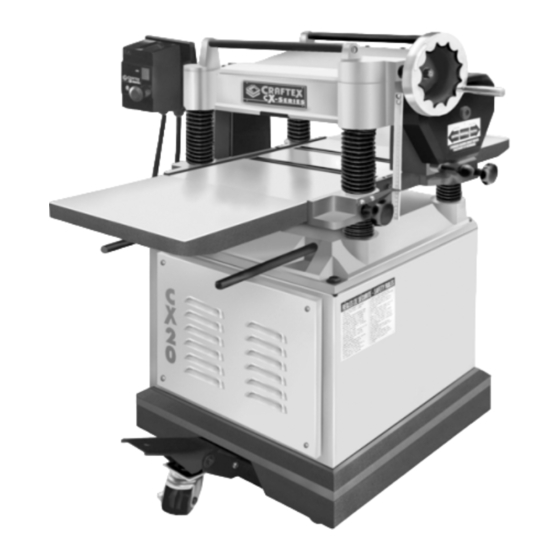
15 inch & 20 inch mobile planers
Hide thumbs
Also See for CX series:
- User manual (49 pages) ,
- Manual (42 pages) ,
- Owner's manual (35 pages)
Table of Contents
Advertisement
Advertisement
Table of Contents


Need help?
Do you have a question about the CX series and is the answer not in the manual?
Questions and answers