Craftex CX Series User Manual

Craftex CX Series User Manual

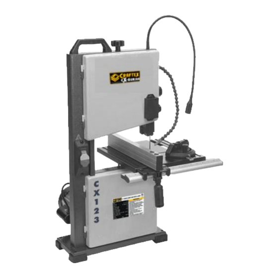
9" wood band saw with laser
Hide thumbs Also See for CX Series:

Advertisement

MODEL CX123
9" WOOD BAND SAW WITH LASER
USER MANUAL
Version 1.0

Advertisement

Table of Contents
loading

Summary of Contents for Craftex CX Series

  • Page 1 MODEL CX123 9" WOOD BAND SAW WITH LASER USER MANUAL Version 1.0...
  • Page 2: Table Of Contents

    TABLE OF CONTENTS Specifications………………………..……………………………………………………………………………..………..3 & 4 General Safety Instructions & Rules……………………………………………………………………………..………..5 & 6 Power Supply................................ 7 Plug and Grounding Requirements ........................8 Unpacking ................................9 Bench Mounting ..............................10 Assembly ................................11 Blade Tracking ..............................13 Dust Collection ..............................15 Blade Tensioning ..............................
  • Page 3: Specifications

    Specifications: Electrical: Power Requirement..............120V, Single-Phase, 60 Hz Full-Load Current Rating.................... 2.8A Minimum Circuit Size....................15A Connection Type....................……….Plug Power Cord Length………………................. 6 ft. Motor: Horsepower....................……….(320W) Phase......................Single-Phase Amps.......................... 2.8A Speed....................... 1720 RPM Type......................ODP Induction Main Specifications: Band saw Size..........................
  • Page 4 Table: Table Length......................12 in. Table Width......................12 in. Table Thickness...................... 5/8 in. Table Tilt......................0 - 45 deg. Table Tilt Adjustment Type................. Rack & Pinion Floor-to-Table Height....................13 in. Fence Locking Position.................... Front Table......................Cast Aluminum Trunnion....................Cast Aluminum Fence........................Aluminum...
  • Page 5: General Safety Instructions & Rules

    GENERAL SAFETY INSTRUCTIONS Extreme caution should be used when operating all power tools. Know your power tool, be familiar with its operation, read through the owner’s manual and practice safe usage procedures at all times. ALWAYS read and understand the user manual before operating the machine.
  • Page 6 CX123 Specific Safety Instructions CX123 is designed for cutting wood only. DO NOT attempt to remove jammed pieces unless the band saw has come to a complete stop and the power switch has ALWAYS INSPECT the blade for any been turned to the OFF position. cracked or missing teeth before operating the band saw.
  • Page 7: Power Supply

    POWER SUPPLY AVAILABILITY OF POWER specified circuit requirements for this piece Before Installation of this machine you will of machinery. need to consider the proximity of your power supply circuit. If available circuits do WARNING!!! not meet the requirements for this machine Do not connect machine to power you will have to get a new circuit installed by before...
  • Page 8: Plug And Grounding Requirements

    may be running at a time please consult If there is an improper connection of a with a qualified electrician to insure the machine grounding wire it may result in a circuit properly sized safe heightened risk of electric shock. If repair or operation.
  • Page 9: Unpacking

    Unpacking This machine has been carefully packed prior to leaving our warehouse. If you discover the machine has been damaged after you have signed for delivery, please immediately call Customer Service or your local Busy Bee Outlet. Save all containers packing materials possible...
  • Page 10: Bench Mounting

    consider is the weight of the operator and Lighting dynamic loading when operating the Shadows, glare or strobe lighting effects can machine. be distracting to an operator so the sources Space Allocation must be eliminated. Good lighting is essential for a safe operation of any When considering the space you need to machine.
  • Page 11: Assembly

    tilt adjustment knob, and shoulder bolt with spring. (Figure D) Figure B Assembly Figure D Before operating the machine it must be 3. Turn the guide post adjustment knob completely assembled. Prior to beginning (Feg.3) counterclockwise and raise the the assembly process refer to Needed for guide post all the way up.
  • Page 12 Figure G Figure F 10. Re-install the wing bolt, lock washer, flat washer, and D-nut (removed in 6. Re-install components removed in step 2. DO NOT fully step 4) on the table assembly. tighten yet. 11. With the fence lock lever in the up 7.
  • Page 13: Blade Tracking

    Band saw wheels are either flat or crowned and both will track differently. This saw has crowned wheels and as the wheels spin, a properly tracking blade will naturally track in the centre of the wheel. (Figure J) Figure I The band saw has multiple components that must be properly adjusted for the best cutting results.
  • Page 14 1. DISCONNECT MACHINE FROM POWER 2. Adjust the upper & lower blade guides away from the blade, and raise the upper guides all the way up. (Refer to Adjusting Blade Guide Bearings for detailed instructions). Note: For this test run, the blade must have approximately same...
  • Page 15: Dust Collection

    5. With moderate pressure push the Recommended CFM at the Dust Port: 100 blade toward the fence. There CFM. The CFM recommendation is not to should approximately ¼” be confused with the dust Collector rating. deflection. If not, then rotate the To determine the CFM at the dust port, tension adjustment knob as need there are variables that need to be...
  • Page 16 3. Turn the machine ON, and verify motor operation, then turn the machine OFF. The motor should run smoothly, without problems unusual Test Run noises. Once you have completely assembled your 4. Remove the key, as shown in (Figure machine, test run it to ensure it is properly connected to the power and all safety components are functioning properly.
  • Page 17: Blade Tensioning

    factors such as improper feed rate, hardness, variations between work pieces, 2. Check that the blade is tracking and improper blade selection affect the properly (see Blade Tracking performance of the machine in a negative section) way. 3. Raise the guide post all the way then To achieve the best results on any type of move upper lower...
  • Page 18: Adjusting Blade Support Bearings

    2. Check that the blade is tracking the blade from pushing backward during properly (see Blade Tracking any cutting operations. When proper section) adjustment is maintained it helps you make accurate cuts and prevents the teeth of the 3. Raise the guide post all the way then blade from coming in contact with the move upper lower...
  • Page 19: Adjusting The Blade Guide Bearings

    Adjusting the Blade Guide Bearings Properly adjusted blade guide bearings provide side-to-side support, from just behind the gullets to the back of the blade, to help keep the blade straight while cutting. These bearings can be adjusted left- Figure N to-right, as well as front to back.
  • Page 20 Figure P Figure R 3. Loosen the guide bearing lock screws (Figure P) 4. Loosen both guide bearing adjustment screws (Figure P), and then position the guide bearings so they evenly and lightly touch the sides of the blade (Figure S) without deflecting it one way or the other.
  • Page 21: Adjusting Miter Slot Parallelism

     If the distances at front & 6. Re-tighten the cap screws to secure the settings. Re-check the setting back are the same, no after tightening. adjustment is necessary  If the distances are not NOTICE equal, will require When changing the blade or adjusting the adjustment, then go to STEP blade tension or tracking, the support and guide bearings must be re-adjusted before...
  • Page 22: Fence Alignment

    Fence Alignment It is imperative that the band saw fence be parallel to the blade to ensure accurate cuts. This can be achieved by aligning the fence to the miter slot. Note: There is a condition that can occasionally arise, even after aligning the fence, a Figure V condition known as “blade lead”.
  • Page 23: Types Of Cuts

    A typical operation process involves the uses a push stick to feed narrow following: work pieces. 1. Examination of the work piece 10. Turns laser sight suitability for cutting necessary) and stops the band saw. 2. Adjusting the table tilt, if necessary, A correctly setup band saw is safer to to the correct angle of the desired operate then other saws and can perform a...
  • Page 24: Disabling Paddle Switch

    2. When cutting around corners try to WARNING! avoid twisting the blade and allow Untrained people or children can be the blade to saw its way around the seriously injured by this machine. The risk corners without forcing. Using relief of injury increases significantly in cases with cuts will help with this if possible.
  • Page 25: Tilting Table & Choosing Blades For Cx123

    3. Rotate the table tilt adjustment 3. After loosening the guide post lock knob until the table reaches the knob use the guide post control desired angle. knob to adjust the height of the blade guard assembly so that the 4.
  • Page 26: Tooth Type

     For curve cutting reference Figure 4 Skip below to help determine the largest These blades are similar to blades except as well as smallest curve that can be for the fact that they are missing every cut using the various blade widths. other tooth for this reason skip tooth blades Always choose the blade that will have a much larger gullet.
  • Page 27: Blade Care & Blade Changing Instructions

    fine tooth blades are used on hard woods Some of the more common reasons for where coarse tooth blades are used with blade brakes are: softer woods.  Poor alignment or adjustment of the Blade Care blade guides. It is important to remember that band saw ...
  • Page 28 CAUTION! Band saw blades are very sharp and can be hard to handle. Heavy gloves should be worn when handling blades to reduce the risk of being cut. To Change The Blade: 1. Make sure that the machine has been disconnected from its power source.
  • Page 29: Ripping & Cross Cutting

    9. Adjust the upper and lower blade Cross cutting is when you are making cuts support guides. against the grain of your material. Cross cuts can be made at 90° when using the 10. Close upper and lower wheel covers fence, however angled cross cuts can made then reinstall the fence, miter when using the miter gauge.
  • Page 30: Maintenance

    immediately and fix the problems before Cutting Curves continuing use of the machine. While cutting curves you have to feed the stock into the blade while rotating your  Worn or damaged electrical wires workpiece at the same time all while trying ...
  • Page 31: Checking Belt Tension

    Checking and Adjusting Belt Tension Figure 8 Adjusting Belt Tension To help ensure optimal performance from your band saw you need to make sure your 1. Make sure the machine has been belt tension is set correctly allowing for the properly disconnected from...
  • Page 32: Belt Replacement

    from the lower wheel shaft and remove the lower wheel. See Figure Belt Replacement If the drive belt is showing noticeable sign of wear, damage or fraying it is in need of replacement. help maintain optimal machine performance the belt must be in good condition.
  • Page 33: Inspecting Wheel Alignment

    If the wheels are set correctly and are coplanar it is more likely to cut straighter without the blade wandering. This will also effectively decrease vibration, heat, and wear on the blade as the blade will automatically be balanced. Make sure the wheels are in alignment may require a combination of shimming a wheel and adjusting the position of the lower wheel shaft.
  • Page 34: Shimming

    NOTE Standard washers can be used to shim the wheel as they can easily be stacked to get the desired height. How to Shim a Wheel: 1. Make sure that the machine has been disconnected properly from its power source. 2.
  • Page 35: Adjusting Shaft Position On Lower Wheel

    5. Remove the wheel that requires CAUTION shimming and place as many If a mistake is made during the following washers necessary to correct the procedure it can be extremely difficult to gap measure in step onto the wheel correct. Before attempting this adjustment shaft.
  • Page 36 If adjustment is required proceed to the next step. Figure 16 7. Retighten the hex nuts loosened it the previous step. Blade Wander/Blade Lead Figure 15 4. Using a pencil mark both the upper Blade lead is when the band saw blade and lower wheels to indicate your wanders away from the cut line when measuring locations.
  • Page 37: Laser Sight Adjustments

    Items Required: 3. Using a clamp secure the board to 4mm Hex Wrench the band saw table. Correcting Blade Lead/Wander 4. Move the band saw fence over to 1. Insure that the blade is correctly the clamped board so that it barely tensioned and that the blade guard touches one end of the board.
  • Page 38 Tools Required #1 Phillips Screwdriver Adjusting Laser Sight 1. Make sure that the machine has been properly disconnected from its power source. 2. Using the screwdriver loosen the Phillips head screws the hold the laser sight in place on the band saw body.
  • Page 39: Parts Diagram & Parts List

    PARTS DIAGRAM...
  • Page 45: Warranty

    WARRANTY CRAFTEX 3 YEARS LIMITED WARRANTY Craftex warrants every product to be free from defects in materials and agrees to correct such defects where applicable. This warranty covers three years for parts and 90 days for labour (unless specified otherwise), to the original purchaser from the date of purchase but does not apply to malfunctions arising directly or indirectly from misuse, abuse, improper installation or assembly, negligence, accidents, repairs or alterations or lack of maintenance.

This manual is also suitable for:

Cx123

Table of Contents