Craftex CX Series Manual
Router table w/lift
Hide thumbs
Also See for CX Series:
- User manual (49 pages) ,
- Manual (36 pages) ,
- Owner's manual (35 pages)
Table of Contents
Advertisement
Quick Links
Advertisement
Table of Contents

Related Manuals for Craftex CX Series


Summary of Contents for Craftex CX Series
- Page 1 MODEL CXR1000 ROUTER TABLE w/LIFT Ver.1 11/20/20...
-
Page 2: Table Of Contents
TABLE OF CONTENTS Identification…………………………………………………………………………………………………………………….. 3 Controls & Components……………………………………………………………………………………………………...4 Router Table Safety…………………………………………………………………………………………………………… 5 Set Up……………………………………………………………………………………………………………………………….. 7 Clean Up……………………………………………………………………………………………………………………………. 9 Site Considerations…………………………………………………………………………………………………………….10 Machine Specifications………………………………………………………………………………………………………12 Construction…… … ……………………………………………………………………………………………………………...13 Assembling Your Router Table………… ………… …………… ……… ……… …… ….. ………………………………15 Router Installation………………………… …… …………………………………………………………………………… 20 Dust Collection &... -
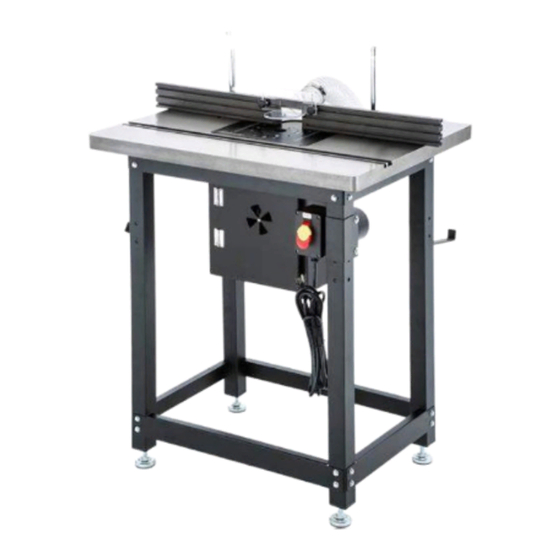
Page 3: Identification
Identification Cast Iron Table with 3/8”T-Slots Dust Port 4” Outfeed fence Router Lift Crank Handle Router Bit Guard Plate Insert Ring Fence Lock (1 of 2) Insert Plate Infeed Fence ON/OFF paddle switch Fence base Dust Box Dust Port 2-1/2” Levelling feet (1 of 4) -
Page 4: Controls & Components
A. 3/8” T-Slot. Used for attaching WARNING! router table accessories, such Read this manual in its entirety as miter gauges, jigs and before using the Router table. Wear feather boards, etc. eye protection. Always keep the router bit guard in place and in good B. -
Page 5: Router Table Safety
F. Fence Locks. For securing the Router Table Safety infeed/outfeed fence positions WARNING! (side to side adjustment). Machinery with cutting bits turning at G. Dust Port. To attach a 4” high speeds can be very dangerous in diameter dust extraction hose certain circumstances and can cause and connect to the users dust very serious injuries, such as cuts,... - Page 6 DO NOT FORCE WORKPIECE: A rule router bit. Doing so can cause the bit of thumb is to always “let the router to fracture and cause injury. bit do the work”. Never force stock CUTTING SUPPORT: Always use a through the router bit. This will likely fence, jig or miter gauge as a support result in poor cutting results and or guide when making your cuts.
-
Page 7: Set Up
SET UP & Bracket Dust Hose 2-1/2” x 28” 1 Tools Required Router Lift Assembly Phillips #1 Screwdriver Table Insert 12mm socket or wrench 36” Straightedge 36” Level 3mm, 5mm, and 12mm Hex Allen Keys 2 x 4 x 12” Wood Block 24”... - Page 8 Box 3 Contents Figure 8 Flange Bolts 5/16-18 x ½ 4 T-Bolts 5/16-18 x 1 Router Bit Guard Star Knobs ¼-20 Dust Port Flat Washers ¼ Fence Storage Brackets 2 Flat Washers 5/16 Fence Base Flat HD Screws ¼-20 x 5/8 Infeed/Outfeed Fences 2 Fence End-caps Hex Nuts ¼-20...
-
Page 9: Clean Up
Adjustable Feet preventative works very well but will Hex Nuts ½-12 take a little time and effort to clean. Flange Bolts 5/16-18 x ½ 36 Be patient and do a thorough job. Lower Short Braces The time you spend doing this will Upper Short Braces give you a better understanding of A10. -
Page 10: Site Considerations
Sometimes a second application The machine weight can be found on may be necessary in some heavily the Machine Data Sheet. For the coated areas. weight of your accessories consult their manufacturer’s operator’s 4. We recommend you coat all manuals. Also to consider is the unpainted surfaces with a quality weight of the operator and dynamic metal protectant to prevent rust. - Page 11 environment subject to vibration, shocks or bumps. Lighting Shadows, glare or strobe lighting Electrical Installation effects can be distracting to an Make sure to place the machine near operator so the sources must be an adequate power source. Ensure all eliminated.
-
Page 12: Machine Specifications
MACHINE SPECIFICATIONS Product Dimensions: Weight…………………………………………………………………………………………………………26 lbs Width x Depth x Height…………………………………………………………….44”x 32”x 44-1/2” Footprint………………………………………………………………………………………………….27” x 19” Shipping Dimensions: Box 1 Type………………………………………………………………………………………………Cardboard Box Content…………………………………………………………………………………………………………Table Weight………………………………………………………………………………………………………….98 lbs Length x Width x Height…………………………………………………………………….36”x 28”x 5” Must Ship Upright……………………………………………………………………………………………. No Box 2 Type………………………………………………………………………………………………Cardboard Box Content…………………………………………………………………………………………………Router Lift Weight………………………………………………………………………………………………………….24 lbs Length x Width x Height………………………………………..………………………….17”x 16”x 15”... -
Page 13: Construction
Power Cord Gauge…………………………………………………………………………………….14 AWG Plug Included…………………………………………………………………………………………………. Yes Plug Type……………………………………………………………………………………………. Nema 5-15 Switch………………………………………………….ON/OFF Paddle Switch w/Removeable Key Main Specifications: Suitable Routers for Mounting………………………………3.25” -4.2” Non-Plunge Routers Floor to Table Height……………………………………………………………………………………36-39” Table Size…………………………………………………………………………………….32 x 24 x 1-1/2” Number of Table T-Slots……………………………………………………………………………………2 Table T-Slot Size………………………………………………………………………………………¾”, 3/8” Plate Size……………………………………………………………………………..9-1/4 x 11-3/4 x 3/8”... - Page 14 Other Specifications: Country of Origin…………………………………………………………………………………………Taiwan Warranty…………………………………………………………………………………………………….3 Years Assembly & Setup Time…………..…………………………………………………………………..1 Hour ISO9000 Factory………………………………………………………………………………………………..Yes Certification (NRTL)……………………………………………………………………………………………No Features: Precision-machined Router Lift Index Ring for Fine Lift adjustment of Router Precision-Ground Cast-Iron Table Clear Polycarbonate Router Guard & Dust Port Fence Assembly with Adjustable fences Enclosed Dust Box Adjustable feet Accessories:...
-
Page 15: Assembling Your Router Table
Assembling Your Router Table 3. Connect the leg assemblies with the (4) long braces supplied with Before beginning this process, consult the 5/16-18 x ½” flange bolts as the Router Table Inventory section to shown in (Fig.13 & Fig.14) ensure all components are available and the Required Setup Tools section to aid in the assembly of the table. - Page 16 7. To align the Router Lift Assembly to the table surface, lay a straightedge across the plate insert and table surfaces in a pattern shown in (Fig.19). Then adjust the set screws (Fig.18) so that the ends of the straight edge lay flat on the surface in all positions of the pattern in (Fig.19).
- Page 17 20 x 5/8 flat head screws, washers and hex nuts. (See Fig.20). Figure 22 Figure 20 10. Insert (2) ¼-20 x ¾” carriage bolts into the centre slot of the infeed fence. (Fig.21), then align the carriage bolts to the vertical slots in the fence base (Fig.22) and secure with (4) ¼”...
- Page 18 Figure 24 Figure 26 13. Assemble the fence locks as in (Fig.25) by removing one ball knob on each handle. Slide it through the hole at the top of the shaft then re-install the ball knobs. 14. Install the fence lock and 5/16 flat washers on each of the T-Bolts installed in step 12.
- Page 19 17. Attach ON/OFF switch assembly to the front RH leg of the stand with (2) ¼-20 x 1-1/2” hex bolts and (2) ¼” flat washers as in (Fig.29). Figure 31 20. Attach the 2-1/2” dust hose on the dust shroud and connect to the Y- Dust Fitting.
-
Page 20: Router Installation
Larger router bodies may need to remove clamping block altogether (Fig.35). Use the clamp and slide blocks to secure the router in this case. Figure 33 Router Installation The Model CXR1000 Router Table will accept Routers with body diameters from 3.25” to 4.25”. It is equipped with four clamping plates, each having curved edges, one deep and one shallow (Fig.34). - Page 21 Figure 36 Figure 37 IMPORTANT! Re-install the lift assembly into When positioning the router in the the router table. clamping plates, take into account access to router controls, such as CAUTION! variable speed dial, depth If the router unexpectedly moves or adjustments, and other locks or the router bit contacts the insert levers.
- Page 22 Leveling The Router Table receptacle (Fig.39). The power cord from the router can be plugged The CXR1000 router table is equipped directly into electrical with adjustable feet in order to allow allowing the operator to switch the you to level the table. Follow the power ON of OFF from the front of following instructions to keep your the machine rather than at the router...
-
Page 23: Dust Collection & Test Run Procedure
Test Run Procedure Install a ½” strain relief on the router power cord where it emerges Once you router table is completely from the dust box and secure by assembled and you have mounted tightening the screws. your router, test run the machine to ensure it is properly connected to the Dust Collection power source and safety components... - Page 24 the router powers up, and then turn the router table switch to OFF. Remove the switch-disabling key, as in (Fig.41) Figure 41 Attempt to restart the router using the paddle switch and the key removed. The router should not start. •...
-
Page 25: Operations
OPERATIONS Set fence adjustments close to router maximum workpiece support, then secure in Operation Overview place. WARNING: Set the router bit height. To help prevent serious injury, read this manual in its entirety before Set the depth of cut by using the machine. -
Page 26: Stock Inspection & Table T-Slots
Stock Inspection NOT designed to cut metal, glass, stone, tile, products containing lead- • DO NOT cut stock that contain based paint, or products containing large or loose knots. If a knot asbestos. Cutting these products becomes dislodged during the cutting could be dangerous for the operator. -
Page 27: Fence, Miter Gauge & Bit Guard
increase/decrease clearance around the router bit. They are secured to the fence base with T- Bolts and knobs (Fig.46). Figure 44 Fence, Miter Gauge & Bit Guard The fence should always be parallel Figure 46 with the table slots when using a miter gauge. -
Page 28: Router Height Adjust & Table Insert Plate
Router Height Adjustment Tighten the lock screw jam nut beneath the insert plate against the Beneath the table insert the CRX1000 plate to secure its position. (Fig.49) is equipped with a manually operated router lift which is operated by a crank handle inserted into the index ring on the top of the insert plate. -
Page 29: Edge Jointing
Edge Jointing Insert a spacer (Not included) between the outfeed fence and the In edge jointing the aim is to get a fence base. The spacer width will perfectly flat and square edge on determine the amount of material your board. This requires using a that will be removed on each pass. -
Page 30: Profile Routing & Routing Small Stock
Connect the table to the power source and then perform your cut. (Fig.51) Figure 53A Figure 52 CAUTION! ALWAYS make sure the fence and Figure 53B router guard properly positioned secured before Both infeed and outfeed fences connecting power. Failing to do so must be parallel if using the T-slot. -
Page 31: Making A Zero-Clearance Fence & Free-Hand Routing
Making a zero-clearance fence DISCONNECT THE MACHINE FROM POWER! Remove infeed Figure 54 outfeed fences from the fence base. Select a piece of straight, CAUTION! smooth stock that is the same height ALWAYS hold downs and thickness as the infeed/outfeed featherboards and push sticks when fences and approximately 36”... - Page 32 router bit guard, takes a high degree Note: of skill and dexterity. Starting the cut Ensure that any fasteners used will is the most dangerous part of this not come into contact with the router operation. As the router bit first bit during operation.
-
Page 33: Maintenance
MAINTENANCE For a clean and safe router table operation you should vacuum off excess sawdust, wipe down the table with a dry cloth to remove any residual dust not captured by the vacuum. And check weekly for the following possible problems: Figure 57 •... -
Page 34: Trouble Shooting
Toubleshooting Symptom: Workpiece catches on infeed/outfeed fences. Symptom: Machine will not start. Possible Causes: Possible Causes: 1. Fence & table T-slot not square. 1. Switch disabling key removed Possible Solution: 2. Router not connected to router table switch 1. Square fence and table T-slot 3. - Page 35 4. Depth of cut too deep. 2. Nicked or chipped router bit. Possible Solutions: 3. Feeding workpiece too fast. 1. Replace router bit 4. Depth of cut too deep. 2. Increase feed rate. 5. Cutting against the grain. 3. Reverse router direction. Possible Solutions: Take smaller depth of cut (especially with hardwoods)
-
Page 36: Aligning The Insert Plate
1. Use a consistent feed rate 2. Apply constant pressure 3. Adjust fence correctly Aligning The Insert Plate Figure 63 To prevent a workpiece will not catch on the insert plate and cause kick- 5. Adjust the set screws (Fig.64) in back, it must be aligned evenly with the insert plate as necessary so the table surface. -
Page 38: Parts List
Parts list... -
Page 42: Warranty
This warranty shall not apply to consumable products such as blades, bits, belts, cutters, chisels, punches etceteras. Craftex shall in no event be liable for injuries, accidental or otherwise, death to persons or damage to property or for incidental contingent, special or consequential damages arising from the use of our products.
Need help?
Do you have a question about the CX Series and is the answer not in the manual?
Questions and answers