Grandstream Networks GSC3570 User Manual
Hd intercom & facility control station
Hide thumbs
Also See for GSC3570:
- User manual (76 pages) ,
- Quick installation manual (9 pages) ,
- Quick installation manual (8 pages)

Related Manuals for Grandstream Networks GSC3570


Summary of Contents for Grandstream Networks GSC3570
- Page 1 Grandstream Networks, Inc. GSC3570 HD Intercom & Facility Control Station User Manual...
- Page 2 Grandstream Networks, Inc. is not permitted. The latest electronic version of this guide is available for download here: http://www.grandstream.com/support Grandstream is a registered trademark and Grandstream logo is trademark of Grandstream Networks, Inc. in the United States, Europe, and other countries. CAUTION Changes or modifications to this product not expressly approved by Grandstream, or operation of this product in any way other than as detailed by this guide, could void your manufacturer warranty.
- Page 3 GNU GPL INFORMATION GSC3570 firmware contains third-party software licensed under the GNU General Public License (GPL). Grandstream uses software under the specific terms of the GPL. Please see the GNU General Public License (GPL) for the exact terms and conditions of the license.
- Page 4 Increase the separation between the equipment and receiver. • Connect the equipment into an outlet on a circuit different from that to which the receiver is connected. • Consult the dealer or an experienced radio/TV technician for help. P a g e GSC3570 User Manual Version 1.0.3.1...
- Page 5 WLAN 5.3/ 5.6 GHz < 20 dBm; The simplified EU declaration of conformity referred to in Article 10(9) shall be provided as follows: Hereby, [Grandstream Networks, Inc.] declares that the radio equipment type [GSC3570] is in compliance with Directive 2014/53/EU.
-
Page 6: Table Of Contents
GSC3570 Connection & Wiring Diagrams - “Fail Secure” Electric Strike, POE Power Supply ... 22 GSC3570 Connection & Wiring Diagrams - “Fail Safe” Electric lock, 3rd Party Power Supply ... 22 GSC3570 Connection & Wiring Diagrams - “Fail Safe” Electric lock, Power Supply and Wi-Fi .. 23 Connecting GDS37xx with GSC3570 .................... - Page 7 Reset ............................41 CONFIGURATION VIA WEB BROWSER ..............42 Definitions ............................43 Status Page Definitions ........................ 44 Accounts Page Definitions ......................45 Settings Page Definitions ......................56 Network Page Definitions ......................61 P a g e GSC3570 User Manual Version 1.0.3.1...
- Page 8 No Touch Provisioning ......................... 81 RESTORE FACTORY DEFAULT SETTINGS ............... 82 Restore to factory using Web GUI ....................... 82 Restore to factory using LCD menu ..................... 82 EXPERIENCING GSC3570 ..................84 P a g e GSC3570 User Manual Version 1.0.3.1...
- Page 9 Table of Tables Table 1: GSC3570 Features in a Glance ....................13 Table 2: GSC3570 Technical Specifications ....................13 Table 3: Equipment Packaging ........................15 Table 4: GSC3570 Wiring Connection ......................16 Table 5: GSC3570 LCD Menu ........................32 Table 6: Status Page Definitions ......................... 44 Table 7: Account Page Definitions ......................
- Page 10 Table of Figures Figure 1: GSC3570 Package Content ......................15 Figure 2: GSC3570 Wiring Connection ....................... 16 Figure 3: Built in Stand and Mounting Slots on The GSC3570..............17 Figure 4: On-Wall Mounting ........................18 Figure 5: In-Wall Mounting .......................... 19 Figure 6: GSC3570 web interface .......................
-
Page 11: Document Purpose
DOCUMENT PURPOSE This document describes how to configure the GSC3570 features via LCD menu and Web GUI menu. To learn the basic functions of GSC3570, please visit http://www.grandstream.com/support to download the latest User Manual. This guide covers the following topics: •... -
Page 12: Change Log
CHANGE LOG This section documents significant changes from earlier versions of user manual for GSC3570. Only major new features or major document updates are listed here. Minor updates for corrections or editing are not documented here. Firmware Version 1.0.3.1 •... -
Page 13: Welcome
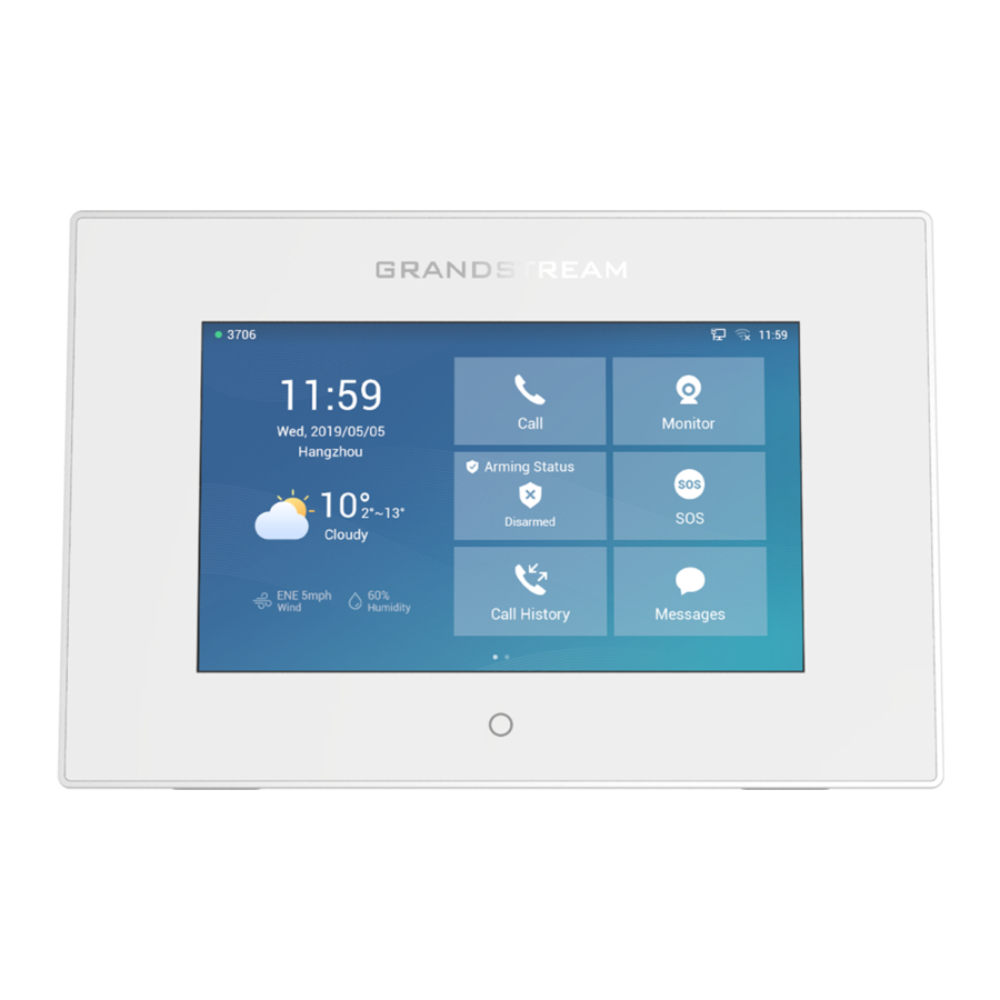
WELCOME Thank you for purchasing Grandstream GSC3570 Integrated SIP Intercom Phone. The GSC3570 is a powerful Intercom phone for door control and 2-way intercom. It features a 7” 1024x600 touch screen LCD, integrated dual-band 802.11ac Wi-Fi, 100M network port with PoE, full duplex 2-way HD audio with advanced AEC, and innovative telephony functionalities. -
Page 14: Product Overview
PRODUCT OVERVIEW Feature Highlights The following tables contain the major features of GSC3570. Table 1: GSC3570 Features in a Glance 4 lines 7” 1024x600 touch screen LCD TFT LCD with Home Key GSC3570 2-way HD audio with advanced AEC ... - Page 15 Temperature and Operation: -10°C to 50°C, Storage: -20°C to 60°C, Humidity Humidity: 10% to 90% Non-condensing Package Contents GSC3570 Intercom Phone, quick installation guide, wall mount bracket, and desktop stand (optional) Compliance FCC, CE, RCM, IC P a g e GSC3570 User Manual Version 1.0.3.1...
-
Page 16: Getting Started
GETTING STARTED This chapter provides basic installation instructions including the list of the packaging contents and information for obtaining the best performance with the GSC3570. Equipment Packaging Table 3: Equipment Packaging GSC3570 • 1x GSC3570. • 1x Installation Bracket •... -
Page 17: Gsc3570 Wiring Connection
GSC3570 Wiring Connection The following figure and table below show the Connection PINs available on the GSC3570: Figure 2: GSC3570 Wiring Connection Table 4: GSC3570 Wiring Connection Port Jack Function Remark Signal Color 1 Relay output, normal open or close, max 125VAC/0.5A or max... -
Page 18: Gsc3570 Setup
Data exchange If needed, please use 5V/2A adapter. GSC3570 Setup The GSC3570 can attached on the wall or in-wall using the slots for wall mounting. Figure 3: Built in Stand and Mounting Slots on The GSC3570. P a g e GSC3570 User Manual Version 1.0.3.1... -
Page 19: On-Wall Mounting
On-Wall Mounting The GSC3570 can be mounted on the wall or on the desktop (desktop bracket is sold separately). Please refer to the following steps for Wall installation: 1. Locate the equipment holder on the desired position. Drill four holes on the wall referring to the positions of the ones on the metal bracket. -
Page 20: In-Wall Mounting
Figure 5: In-Wall Mounting Connecting the GSC3570 To setup your GSC3570 from the web interface, please follow the steps below: 1. Ensure your device is powered up and connected to the Internet. 2. Slide to the second home page and press "Setting"... -
Page 21: Figure 6: Gsc3570 Web Interface
To setup your GSC3570 from the LCD, please follow the steps below: 1. Make sure the device is idle. 2. Slide to the second home page and press "Setting". Browse the GSC3570 MENU for Status, Network information, Features and Basic/Advanced Settings... -
Page 22: Alarm In/Out
• The Alarm_In circuit, if there is any voltage change between 9V and 15V, as specified in the table above, the GSC3570 Alarm_In port will detect it and trigger the action and event. • Higher voltage and wrong polarity connection are prohibited because this will damage the devices. -
Page 23: Connection Examples
GSC3570 Connection & Wiring Diagrams - “Fail Secure” Electric Strike, POE Power Supply Figure 8: Fail Secure” Electric Strike, POE Power Supply GSC3570 Connection & Wiring Diagrams - “Fail Safe” Electric lock, 3rd Party Power Supply Figure 9: Fail Safe” Electric lock, 3rd Party Power Supply... -
Page 24: Gsc3570 Connection & Wiring Diagrams - "Fail Safe" Electric Lock, Power Supply And Wi-Fi
GSC3570 Connection & Wiring Diagrams - “Fail Safe” Electric lock, Power Supply and Wi-Fi Figure 10: Fail Safe” Electric lock, 3rd Party Power Supply, Wi-Fi Connecting GDS37xx with GSC3570 The GSC3750 can be configured with up to 10 GDS37xx devices allowing two doors remote control per... -
Page 25: Figure 11: External Service: Web Configuration
Figure 11: External Service: Web Configuration LCD configuration: 1. Tap the menu button if GSC3570 is in idle state. 2. On the first screen menu, tap Monitor→ Door System. 3. Press the ADD or button to add a new GDS. -
Page 26: Connecting Ip Camera With Gsc3570
Figure 12: External Service: LCD Configuration Connecting IP Camera with GSC3570 The GSC3750 can be configured with up to 32 IP Camera devices allowing two doors remote control per GDS, the configuration is done as follow: Web interface configuration: 1. Access Settings→ IPC. -
Page 27: Figure 13: Ipc: Web Configuration
5. Select which Account to make outgoing call towards the IP Camera and enter the IP Camera’s SIP extension (or IP address in case of peering scenario) in Device Number field. Figure 14: IPC: LCD Configuration P a g e GSC3570 User Manual Version 1.0.3.1... -
Page 28: Arming Mode
• Both the Entering/Exiting Delay duration got a range from 0s to 60s. • The GSC3570 supports up to 4 zones. • Once the Zone(s) is configured, proceed from Features → Arming Mode: On each Profile (Outdoor, Indoor, Sleeping, Custom) User can enable the zones. -
Page 29: Alarm & Sos Calling
Alarm & SOS Calling The GSC3750 can be configured with a SOS key as when this key is hold the GSC3570 will trigger will be ringing the extension(s) configured under SOS panel from either the web GUI or LCD Menu. -
Page 30: Figure 18: Sos: Web Configuration
4. Select the Account from which the call will be made and enter the SIP extension or IP address to be called. (Default is Dynamic, so the GSC will use the first available line). 5. Click on Save button. P a g e GSC3570 User Manual Version 1.0.3.1... -
Page 31: Figure 19: Sos: Lcd Configuration
The GSC3570 can be set with trigger button to execute the Alarm output action and numbers configured on Alarm panel on either the web interface will be ringing as well. Figure 19: SOS: LCD Configuration Web interface configuration: 1. Access Settings→ Alarm. -
Page 32: Figure 21: Alarm: Lcd Configuration
LCD configuration: 1. Tap the menu button if GSC3570 is in idle state. 2. On the first screen menu, tap Settings app → Advanced → Alarm Settings. 3. Set Call Mode to either Serial Hunting where each number will be called one after one based in the order from 1-4 after first call times out, or Parallel Hunting where all configured numbers receive the call simultaneously. -
Page 33: Gsc3570 Lcd Settings
GSC3570 LCD SETTINGS The GSC3570 LCD MENU provides an easy access to the settings on the GSC3570. Some of the settings from Web GUI could be configured via the LCD as well. The following table shows the LCD menu options. -
Page 34: Access Lcd Settings
Date&Time Weather settings Reboot • Advanced Accounts Monitor Alarm settings SOS settings Syslog System updates Reset Access LCD Settings The following diagram describe the LCD Menu and sub-menus: P a g e GSC3570 User Manual Version 1.0.3.1... -
Page 35: Figure 22: Menu Configuration
Language Date & Time Weather Settings Reboot Status Screen lock Network Settings Features Basic Accounts Advanced Monitor SD Card Alarm Settings SOS Settings Syslog System Updates Reset Figure 22: MENU Configuration P a g e GSC3570 User Manual Version 1.0.3.1... -
Page 36: Status
To open the settings menu, you should: • Tap on Settings app on the screen. Figure 23: GSC3570 System Settings Status Account Status This page displays all available accounts on the phone with respective status (Configured/Not Configured and Registered/Unregistered). Network Status This page displays Network status including IPv4/v6 address, subnet mask, gateway, DNS server…... -
Page 37: Network
If enabled and set to "Enable Intercom/Paging", the phone will answer the call based on the SIP info header sent from the server/proxy. By default, it is turned off. Enable/Disable the DND mode. When enabled, all incoming calls are rejected. P a g e GSC3570 User Manual Version 1.0.3.1... -
Page 38: Arming Mode
Use the Voice settings to configure the phone's sound mode, volume, ring tone and notification tone. • Media Volume: Adjust the sound volume for media audio • Ring Volume: Adjust the phone ringing volume • Ringtone: Select phone's ringtone for incoming call. P a g e GSC3570 User Manual Version 1.0.3.1... -
Page 39: Display
Enable back LED indicator: Enable/disable the back LED indicator. Language • Language: Tap to open the list of available languages. Selected language will be used on GSC3570. By default, it is set to “Auto” to automatically select best matching language from available languages based on GSC3570 location. -
Page 40: Reboot
• Automatic Update: Enable the weather update feature. • Update Interval: Configure the weather update interval in minutes. Default is 15 minutes. Reboot • Reboot the GSC3570. Screen Lock • Enable/Disable screen lock and define the 6-digits password. Advanced Accounts Set up to 4 SIP accounts. -
Page 41: Alarm Settings
System log protocol: Select the protocol of syslog (UDP or SSL/TLS). • Syslog server address: The URL/IP address for the syslog server. If the GSC3570 has network connection, the phone will send the syslog packets to this server address. •... -
Page 42: System Update
❖ Config Server Username: Configures the username for the Config HTTP/HTTPS server. ❖ Config Server Password: Configures the password for the Config HTTP/HTTPS server. ❖ Config Server Path: Configure the Config server path. Reset • Factory reset the device to default settings. P a g e GSC3570 User Manual Version 1.0.3.1... -
Page 43: Configuration Via Web Browser
To access the Web GUI: 1. Connect the computer to the same network as the GSC3570. 2. Make sure the GSC3570 is turned on and shows its IP address. You may check the IP from the LCD Menu →Settings →Status →Network Status. -
Page 44: Definitions
“Accounts” page and “Phonebook” page do not require reboot. Most of the options under “Settings” page do not require reboot). Definitions This section describes the options in the GSC3570’s Web GUI. As mentioned, you can log in as an administrator or an end user. •... -
Page 45: Status Page Definitions
PPPoE Link Up PPPoE Link status NAT Type Displays the configured NAT type NAT Traversal Display the status of NAT connection for each account on the GSC3570. Status → System Info Product Model Product model of the GSC3570. Part Number Product part number. -
Page 46: Accounts Page Definitions
This is provided by your VoIP service provider (ITSP). The URL or IP address, and port of the SIP server. When configured, GSC3570 will register to both Primary and Secondary SIP Server. If Primary Secondary SIP Server SIP Server is not reachable then the GSC3570 will use Secondary SIP Server for GSC3570 services (including making/receiving calls). - Page 47 This parameter allows you to access voice messages by pressing the Voice Mail Access MESSAGE button on the GSC3570. This ID is usually the VM portal access Number number. For example, in UCM6xxx IPPBX, *97 could be used. Account x → Dial Plan Name Enter the name for the configured rules.
- Page 48 “Primary IP” or “Backup IP x” to send SIP message if at least one of them are not empty. GSC3570 will try to use “Primary IP” first. After 3 tries without any response, it will switch to “Backup IP x”, and then it will switch back to “Primary IP” after 3 re-tries.
- Page 49 GSC3570 reboots. The SIP Contact header will contain “*” to notify the server to unbind the connection. • If set to “Instance”, the SIP user will be unregistered on current GSC3570 only. • If set to “No”, the GSC3570 will not unregister the SIP account when rebooting.
- Page 50 100rel tag is appended to the value of the required header of the initial signaling messages. The default setting is “No”. When set to “Auto”, the GSC3570 will update the callee ID in the order of P- Callee ID Display Asserted Identity Header, Remote-Party-ID Header and To Header in the 180 Ringing.
- Page 51 When set to “To Header”, caller ID will not be updated and displayed as To Header. When set to “Auto”, the GSC3570 will look for the caller ID in the order of P- Asserted Identity Header, Remote-Party-ID Header and From Header in the incoming SIP INVITE.
- Page 52 Huawei IMS, PhonePower and UCM Call center depending on the server type. The default setting is “Standard”. Session Timer This option is used to enable or disable session timer on the GSC3570 side Enable Session Timer when server side can provide both session timer UPDATE or session audit UPDATE.
- Page 53 Default setting is “No”. If Force Timer is set to “Yes”, the GSC3570 will use the session timer even if the remote party does not support this feature. If Force Timer is set to “No”,...
- Page 54 Default setting is AES 128&256 bit Enable or disable the crypto lifetime when using SRTP. If users set to disable Crypto Lifetime this option, GSC3570 will not add the crypto lifetime to SRTP header. The default setting is “Yes”. Symmetric RTP Defines whether symmetric RTP is supported or not.
- Page 55 Configures the delay between sending DTMF (in milliseconds). Default is DTMF Delay 250 ms. Video Settings H.264 Image Size Sets the H.264 image size. It can be selected from the dropdown list. • 720P • 4CIF • • • QVGA P a g e GSC3570 User Manual Version 1.0.3.1...
- Page 56 Account x → Call Settings If set to “Yes”, the “From” header in outgoing INVITE messages will be set to Send Anonymous anonymous, blocking the Caller ID to be displayed. Default is “No”. P a g e GSC3570 User Manual Version 1.0.3.1...
-
Page 57: Settings
If set to “Yes”, anonymous calls will be rejected. Rejection The default setting is “No”. If set to “Yes”, the GSC3570 will automatically turn on the speakerphone to Auto Answer answer incoming calls after a short reminding beep. Default setting is “No”. - Page 58 Note: This parameter must be set to “No” for Direct IP Calling to work. Specifies how often the GSC3570 sends a blank UDP packet to the SIP server to keep the “ping hole” on the NAT router to open. The default setting Keep-alive Interval is 20 seconds.
- Page 59 Configured SIP Numbers will receive the call simultaneously. Order (1-4) Displays the order of the service. When set to “Dynamic”, the GSC3570 will use the first available Account. Account User can specify from which account the call can be made for each destination.
-
Page 60: Table 8: Settings
Agent” should be prepend to vendor’s default User. Settings → Preferences → Date and Time Defines the URL or IP address of the NTP server. The GSC3570 may obtain NTP Server the date and time from the server. The default setting is “pool.ntp.org”. - Page 61 Allows user to set up the backlight time (in minutes) for the extension board. Active Backlight Valid range from 0 to 90. Default value is 1. Timeout Note: When Active Backlight Timeout is set to 0, the backlight will be constantly on. P a g e GSC3570 User Manual Version 1.0.3.1...
-
Page 62: Network Page Definitions
Preferred DNS Server Enters the Preferred DNS Server for IPv4. Network → Advanced Settings Allows the user to enable/disable 802.1X mode on the GSC3570. The default 802.1X mode value is disabled. To enable 802.1X mode, this field should be set to EAP- MD5, users may also choose EAP-TLS, or EAP-PEAP/MSCHAPv2. - Page 63 Uploads / deletes 802.1X Client certificate to the GSC3570; or delete existed Certificate 802.1X Client certificate from the GSC3570. Specifies the HTTP proxy URL for the GSC3570 to send packets to. The HTTP Proxy proxy server will act as an intermediary to route the packets to the destination.
- Page 64 Note: Please use this option with caution. Make sure that the options are recognizable by OpenVPN® and do not unnecessarily override the other configurations above. Network → SNMP Settings Enables/Disables the SNMP feature. Default settings is No. Enable SNMP P a g e GSC3570 User Manual Version 1.0.3.1...
- Page 65 Enter the Authentication Key. Authentication Key Enter the Privacy Key. Privacy Key Username for SNMPv3 Trap. SNMP Trap Username • Trap Security Level noAuthUser: Users with security level noAuthnoPriv and context name P a g e GSC3570 User Manual Version 1.0.3.1...
-
Page 66: Maintenance Page Definitions
Maintenance Page Definitions Table 10: Maintenance Page Definitions Maintenance → Web Access User Password Set new password for web GUI access as User. New Password Note: This field is case sensitive. P a g e GSC3570 User Manual Version 1.0.3.1... - Page 67 DHCP option 43 vendor specific option to do this. Override Server DHCP option 43 approach has priorities. The GSC3570 will fall back to the original server path configured in case the server from option 66 fails. When enabled, users could select Option 150 or Option 160 to override the...
- Page 68 Device will not challenge NOTIFY with 401 when set to “Yes”. Authentication Default setting is “No”. If set to "Yes" (Default), the GSC3570 will ask the user to upgrade. If there Firmware Upgrade is no response, the GSC3570 will proceed with the upgrade.
- Page 69 Download and Process specific, model specific and global configs). All Available Config If this option is enabled, the GSC3570 will inverse the downloading process Files to cfg.xml > cfgGSC3570.xml > cfgMAC.bin > cfgMAC.xml. The following files will override the files that has already been load and processed.
- Page 70 Default setting is UDP. Note: The CA certificate is required to connect with the TLS server. URL or IP address of the syslog server for the GSC3570 to send syslog to. Note: By adding port number to the Syslog server field (i.e.
- Page 71 Maintenance → Security Settings→ Security After enabling this feature, GSC3570 will validate the server’s certificate. If Validate Server the server that our GSC3570 tries to register on is not on our list, it will not Certificates allow server to access the GSC3570.
-
Page 72: Directory Page Definitions
Note: If the contact number belongs to Blacklist group, the call from this number will be blocked. If the contact number belongs to Whitelist group, when the GSC3570 is on DND mode, the call from whitelist number will be allowed. - Page 73 Download XML Click on "Download" to download the XML Phonebook file to local PC Phonebook Upload XML Click on "Upload" to upload local XML Phonebook file to the GSC3570. Phonebook Configures default phonebook search mode. • Quick Match: The quick search feature allows users to search parts and strings of the entries.
- Page 74 (&(cn=%) (telephoneNumber=*)) returns all the records with the "cn" field starting with the entered prefix and "telephoneNumber" field set. Selects the protocol version for the GSC3570 to send the bind requests. The LDAP Version default setting is "Version 3".
-
Page 75: Nat Settings
It is under Accounts X→Network Settings. Default setting is "No". Enable the device to use NAT traversal when it is behind firewall on a private network. Select Keep-Alive, Auto, STUN (with STUN server path configured too) or other option according to the network setting. P a g e GSC3570 User Manual Version 1.0.3.1... -
Page 76: Dial Plan Configuration
Prefix: The rules you set in combination with this type will include configured prefix automatically. If Replaced was set, your used prefix will replace the “Replaced” value. For example: If Dialed 3456, the DTMF will send 123456. See configuration below. P a g e GSC3570 User Manual Version 1.0.3.1... - Page 77 • Company • Department. • Job. • Job Title. • Work. • Home. • Mobile. • Account. • Groups • Ring Tone (Set specific ring tone for the contact). • Picture. P a g e GSC3570 User Manual Version 1.0.3.1...
-
Page 78: Phonebook - Immediate Download
Download on LCD. Figure 27: Download XML phonebook • Phonebook Download Interval: After each time the interval set for “Phonebook Download Interval” passes, the Intercoms will download the Phonebook. P a g e GSC3570 User Manual Version 1.0.3.1... -
Page 79: Saving Configuration Changes
Rebooting from Remote Locations Press the "Reboot" button on the top right corner of the web GUI page to reboot the GSC3570 remotely. The web browser will then display a reboot message. Wait for about 1 minute to log in again. -
Page 80: Upgrading And Provisioning
Follow the steps below to configure the upgrade server path via LCD menu: • Press MENU button and navigate to System. • In the System options, tap System Updates. • Click Update now. Figure 29: LCD upgrade P a g e GSC3570 User Manual Version 1.0.3.1... -
Page 81: Upgrade Via Web Gui
Upgrade via Web GUI Open a web browser on PC and enter the IP address of the GSC3570. Then, login with the administrator username and password. Go to Maintenance→Upgrade and Provisioning page, enter the IP address or the FQDN for the upgrade server in "Firmware Server Path" field and choose to upgrade via TFTP or HTTP/HTTPS or FTP/FTPS. -
Page 82: No Touch Provisioning
Web GUI→Maintenance→Web Access page→Admin Password. For a detailed parameter list, please refer to the corresponding configuration template. When the GSC3570 boots up or reboots, it will issue a request to download a configuration file named "cfgxxxxxxxxxxxx" followed by an XML file named "cfgxxxxxxxxxxxx.xml", where "xxxxxxxxxxxx" is the MAC address of the GSC3570, i.e., "cfg000b820102ab"... -
Page 83: Restore Factory Default Settings
Grandstream is not responsible for restoring lost parameters and cannot connect your device to your VoIP service provider. There are two methods to perform factory reset on GSC3570 IP Intercom series which are described below. Restore to factory using Web GUI From the web GUI and as shown on the following screenshot, users need to access Maintenance→Tools... -
Page 84: Figure 31: Factory Reset From Lcd
Figure 31: Factory Reset from LCD P a g e GSC3570 User Manual Version 1.0.3.1... -
Page 85: Experiencing Gsc3570
Thank you again for purchasing Grandstream GSC3570 IP Intercom, it will be sure to bring convenience and color to both your business and personal life. P a g e GSC3570 User Manual Version 1.0.3.1...
Need help?
Do you have a question about the GSC3570 and is the answer not in the manual?
Questions and answers