Grandstream Networks GDS3705 User Manual
Audio door access system
Hide thumbs
Also See for GDS3705:
- User manual (110 pages) ,
- Quick installation manual (13 pages) ,
- Quick reference manual (10 pages)
Advertisement
Quick Links
Download this manual
See also:
User Manual
U S E R G U I D E | C L O U D C O M M U N I C A T I O N S
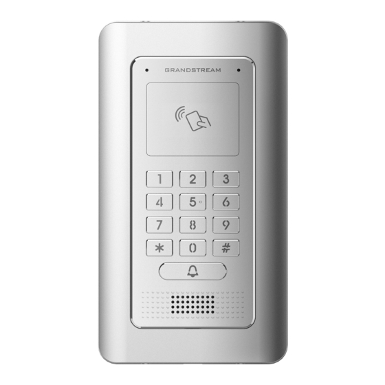
GDS3705
Audio Door Access System
Quick Installation Guide
March 2019
Advertisement

Subscribe to Our Youtube Channel
Related Manuals for Grandstream Networks GDS3705


Summary of Contents for Grandstream Networks GDS3705
- Page 1 U S E R G U I D E | C L O U D C O M M U N I C A T I O N S GDS3705 Audio Door Access System Quick Installation Guide March 2019...
-
Page 2: Package Contents
Do not expose this device to environments outside of the following humidity range: 10-90% RH (non-condensing) • Please strictly follow the instruction to install or hire professionals to install properly PACKAGE CONTENTS 1 x GDS3705 1 x Installation Bracket 1 x Drilling Template 3x Rubber Gaskets... - Page 3 Step 2: Pull Cat5e or Cat6 cable (not provided) through the rubber gasket selecting the correct size and the back cover panel piece, please refer to “GDS3705 WIRING TABLE” at the end of QIG for Pin connections. Note: Needle nose plier highly recommended and 2.5mm flat screwdriver required (not provided). Stripping outer plastic shield of the cable in less than 2 inches suggested.
- Page 4 Step 4: Take out the two preinstalled anti-tamper screws using the hex key provided. Carefully align the GDS3705 to the metal bracket on wall, press and pull the GDS3705 down to the right position.
- Page 5 CONNECTING THE GDS3705 Refer to the illustration below and follow the instructions on the next page. POWER OFF GDS3705 when connecting wires or inserting/removing the back cover panel piece! Option A: RJ45 Ethernet Cable to (Class 3) Power over Ethernet (PoE) Switch.
- Page 6 The GDS3705 is by default configured to obtain the IP address from DHCP server where the unit is located. In order to know which IP address is assigned to your GDS3705, please use GS Search tool as illustrated in following steps.
- Page 7 GDS 3 7 0 5 AU DI O DO O R AC C ES S SYST E M - Q UI C K IN STA L L AT I ON G UI D E Step 5: Open the web browser and type the displayed IP address of GDS3705 with leading https:// to access the web GUI. (For security reasons, the default web access of GDS3705 is using HTTPS and port 443.) Step 6: Enter username and password to login.
- Page 8 Wiegand Output Signal WG_D0_OUT (Brown) LED (Blue) Wiegand Output LED Signal (Special) WG_D1_IN (White) 2.0mm Wiegand Input Signal WG_D0_IN (Green) Beep (Yellow) Wiegand Output BEEP Signal 5V (Red) Wiegand Power Output For more details regarding GDS3705 wiring, please refer to User Manual.
- Page 9 GDS 3 7 0 5 AU DI O DO O R AC C ES S SYST E M - Q UI C K IN STA L L AT I ON G UI D E Electric Lock GDS3705 Connection Door Type...
Need help?
Do you have a question about the GDS3705 and is the answer not in the manual?
Questions and answers