Table of Contents
Advertisement
Quick Links
Advertisement
Table of Contents

Subscribe to Our Youtube Channel
Related Manuals for Grandstream Networks GDS371 Series


Summary of Contents for Grandstream Networks GDS371 Series
- Page 1 Grandstream Networks, Inc. GDS371X User Manual GDS3712 GDS3710...
-
Page 2: Product Overview
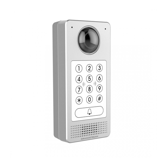
GDS371x - User Manual WELCOME Thank you for purchasing Grandstream GDS3710/GDS3712. The GDS3710 is an IP Video Door System that also serves as a high-definition IP surveillance camera and IP intercom to offer facility access control and security monitoring for buildings of all sizes. This powerful IP Video Door System offers a 180-degree video viewing angle for wall- to-wall coverage, has a built-in RFID chip reader for secure keyless entry, includes a built-in microphone and speaker to support intercom functionality, and offers alarm-in and alarm-out support for integration with existing security devices. - Page 3 The following table resumes all the technical specifications including the protocols/standards supported, voice codecs, telephony features, and upgrade/provisioning settings for GDS371x. Video Compression H.264 High Profile / Main Profile / Base Profile, Motion JPEG. Image Sensor Resolution 1/2.7”, 2 Megapixel, 1920H x 1080V. Lens Type 1/2”, F2.5, FOV: 180°(W) x 150°(H).
- Page 4 Network Interface 10M/100M auto-sensing. Expansion Interface Wiegand (26 bits) input and output. 173mm(H) x 80mm(W) x 36mm(D). Dimensions and Weight 0.6 Kg. PoE (Power over Ethernet) IEEE 802.3af Class 3, or 12VDC/1A Power Supply connection (AC power adapter not included). Interoperability ONVIF (Profile S).
-
Page 5: Getting Started
Voice Codecs G.711µ/a-law, G.722, G.729A/B, DTMF (RFC2833, SIP INFO), AEC. Layer 2 QoS (802.1Q, 802.1P) and Layer 3 QoS (ToS, DiffServ, MPLS). User and administrator level access control, MD5 and MD5-sess based Security authentication, 256-bit AES encrypted configuration file, TLS, SRTP, HTTPS, 802.1Q. - Page 6 ● 1 x Drilling Template. ● 1 x RFID Card (more can be purchased from Partner/reseller). ● 1 x Protecting Cap. ● 1 x Key Fob (more can be purchased from Partner/reseller) ● 4 x Rubber Gaskets (for sealing the back cable). ●...
- Page 7 GDS3710 Front and Back View GDS3712 GDS3712 Front and Back View Connecting and Setting up the GDS371x The GDS371x can be powered using PoE or PSU: Using PoE as power supply (Suggested) Connect the other end of the RJ45 cable to the PoE switch. PoE injector can be used if PoE switch is not available.
- Page 8 ALARM1_IN+ Alarm In Vin<15V ALARM1_IN- ALARM2_IN+ ALARM2_IN- Alarm Out Relay: 30VDC/2A; 125VAC/0.5A COM1 For "Fail Secure" (Locked when Power Lost) Strike, connect COM2 & NO2. COM2 Electric Lock For "Fail Safe" (Open when No Power) Magnetic Lock, connect COM2 & NC2. Relay: ...
-
Page 9: Connection Example
GDS371x Back Cover Connections Connection Example To connect the GDS either by using PoE or PSU follow steps below: Open the Back-Cover Board of the GDS371x which should look like following figure. GDS371x Back Cover Power the unit using PoE Cut into the plastic sheath of your Ethernet cable, then Unwind and pair as shown below. -
Page 10: Power The Unit Using Psu
Connect each wire of the cable to its associate on the Back Cover of the GDS371x to power the unit using PoE. Power the unit using PSU To power the unit using PSU, use a multimeter to detect the polarity of your Power Supply, then connect GND to negative pole and 12V to positive pole of the PSU. -
Page 11: Gds Manager Utility Tool
Detecting GDS371x via UPnP 3. Click on the displayed icon of related GDS3710, the default browser (e.g.: Internet Explorer, Firefox or Chrome) will open and connect directly to the login webpage. GDS3710 Login Page 4. Once logged in, the prompt message will display asking for plug-in installation. 5. -
Page 12: Apple Platform
3. On the GDS Manager access to Device �� Search and Click on the button to start device detection 4. The detected devices will appear in the output field like below: GDS3710x Detection 5. Double click the column of the detected GDS371x, the browser will automatically open and show the device’s web configuration page. 6. - Page 13 6. The browser will ask for plug-in or ActiveX if not installed, otherwise it will get to Home page and show web interface of GDS371x. 7. Access the Web Configuration Interface. Internet Explorer will indicate that “This website wants to install the following add-on: GSViewerX.cab from Grandstream Networks Inc.”, allow the installation. Note...
-
Page 14: Peering Mode Without Sip Server
Please disable temporarily Antivirus or Internet Security Software and close all browsers when download and install the Grandstream Plug-in Software. GDS371x APPLICATION SCENARIOS The GDS371x Door System can be used in different scenarios. Peering Mode without SIP Server For environment like remote warehouse/storage, grocery store, small (take-out) restaurants, just using static IP with PoE switch to form a LAN, using Grandstream’s video phone GXV3x50 or GXV3x70, the GDS371x will meet your very basic intercom, open door and surveillance requirement. - Page 15 Several GDS371x NVR supporting Onvif Profile S. PoE switches with Cat5e/Cat6 wiring. Router. Internet Access (Optical fiber, 3G, 4G, Cable or DSL). iPhone or Android phone with 3rd party APP. Figure 16: Peering GDS3710 with an Onvif Profile S NVR. GDS371x PERIPHERAL CONNECTIONS Below is the illustration of GDS371x peripheral connections for related applications, We will take the GDS3710 as our testing unit.
-
Page 16: Alarm In/Out
Alarm IN/OUT Alarm_In could use any 3rd party Sensors (like IR Motion Sensor). Alarm_Out device could use 3rd party Siren and Strobe Light, or Electric Door Striker, etc. The figure below shows illustration of the Circuit for Alarm_In and Alarm_Out. Alarm_In/Out Circuit for GDS371x Notes: The Alarm_In and Alarm_Out circuit for the GDS371x should meet the following requirement:... -
Page 17: Rd Party Power Supply
Below examples, show how to use wiring on the back cover of the GDS3710 to connect with external devices. The “NO” (Normal Open) model strike is used as example, “NC” (Normal Closed) should be similar and users need to decide which model (NO or NC) to be used on the door. Wiring Sample using 3 Party Power Supply 3 party Power Supply Wiring Sample... -
Page 18: Good Wiring Sample For Electric Strike And High-Power Device
Example to Avoid when Powering the Electric Strike Good Wiring Sample for Electric Strike and High-Power Device Electric Strike and High-Power Device Example Wiegand Module Wiring Examples GDS371x package is shipped with one Wiegand cable for Input/Output Wiegand connections. The following examples shows how to connect the Wiegand Input/Output devices to the GDS371x. -
Page 19: Wiegand Rfid Card Reader Example
Input example with power supply for both GDS371x and Wiegand device Wiegand Input Example with Power Supply for GDS3710 and Wiegand Device If power source is 12VDC, Wiegand device can share same power source of GDS371x. However, users need to check the max power consumption and the max capability of the power source. - Page 20 Wiegand RFID Card Reader Example Siren alarming when door opened abnormally When this feature enabled (special wiring required, see below wiring diagram), abnormal open door will be detected by DI port (Alarm_In2 or IN2 in below diagram showed) if wired correctly (connecting the COMx port to DIx port) therefore trigger siren alarm. Once abnormal open door alarm triggered, the siren will sound non-stop, until manually override by related person.
- Page 21 “Fail Secure” Electric Strike using 3rd Party Power Supply GDS371x Connection: IN2 set as Normal Open and “Fail Secure” Electric Strike using 3 Party Power Supply with Door sensor Fail Secure” Electric Strike using 3rd Party Power Supply with Door Sensor GSC3570 Secure Open Door via GDS37XX/GSC3570 Peering This secure open door new feature is a major enhancement to GDS37xx, but need to include GSC3570 to make it a whole solution.
- Page 22 Indoor Device: GSC3570(FW1.0.5.2) The GDS37xx can be powered via PoE, the GSC3570 can connect to same network via PoE or WiFi. For open door combination with GSC3570 and GDS37xx, if GSC3570 needs to control multiple GDS37xx, it has to use SIP and the related GDS37xx will control the strike/lock. The different GDS37xx doorbell call will have“...
-
Page 23: Web Configuration
If the solution/integration is using static IP address without SIP Proxy, all the devices involved (GDS/GSC/IP Phone) should set “NAT Traversal” to “No” and should NOT “Use Random Port”, otherwise will have problem of ghost call (SIP signaling working but NO media). The IP phone or GSC3570 can use any empty SIP account, meaning it can be mixed if Account 1 registered to UCM/Proxy and Account2 (blank) to use IP (but the account has to be configured as “Active”). - Page 24 One-Way Interlocking Mode_GDS3710_Configuration_1 Notes Door 2 Delay before Unlock(s): Will be the total transit time from Door 1 to Door 2 right after the Door 1 is closed (this time will be “Door 1 unlock holding time”). In above example, the Door1 unlock holding time is 2 seconds, the transit time of hallway is 6 seconds, therefore the Door 2 Delay before Unlock is set to 8 seconds.
- Page 25 Digit Input 2 Status: If set to Normal Open: Configured door status check will be triggered when Digital Input Status switch from Close to Open, if set to Normal Close: Configured door status check will be triggered when Digital Input Status switch from Open to Close. By default, Input Digit 2 Status is “Disabled.
- Page 26 Open Door with SIP Call GSC3570 Open Door NO SIP Call: At the GSC3570 idle screen, press “Monitor →Door system”, the related GDS37XX will be displayed. In the blue bar, left is a “Phone”icon and right is the “Open door”icon. The“Phone”icon will establish SIP call as previous firmware behaved. Press “Open door”...
-
Page 27: Maintenance
Open Door without SIP Call GDS371x HOME WEB PAGE Once logged in successfully to the GDS371x, user will see the following page. Note: the options displayed might differ from browser to another, and from a GDS model to another (GDS3710/GDS3712) Home Page: Internet Explorer 11 Number Fields... -
Page 28: Live View Page
Status Click to enter “Status” page. Stream 1 Play the primary stream. Stream 2 Play the secondary stream. Stream 3 Play the third stream. Allows to dial an extension from the web interface and select an account to place the call Calling interface Logout Logout from the web page. -
Page 29: Live Snapshot
Live View Page: Google Chrome Three streams are available: Primary video stream: 1920*1080 resolution, recommended for continuous full HD recording. Secondary video stream: 640*480 resolution (1280 x 720 resolution for GDS3712), recommended for SIP/VoIP video calls (if used with GXV3470/GXV3480). Third video stream: 320*240 resolution, recommended for smartphone or Tablet Apps (IP Cam Viewer for instance). - Page 30 3. The browser will show one frame of the video (720p) as a snapshot. Snapshot view using secured MJPEG authentication Mode Note This is supported on all browsers without installing any plugin and requires admin user authentication for more security. 2).
- Page 31 The GDS371x supports MJPEG Stream live viewing via HTTP API commands, this can be used without installing the Live view browser plugin. Starting from firmware 1.0.3.34, users can deploy two methods to retrieve MJPEG stream depending on JPEG Authentication Mode, which can be set under following path: Web UI ��...
- Page 32 Figure 56 : MJPEG live view using secured MJPEG Authentication Mode Note This is supported on all browsers without installing any plugin and requires admin user authentication for more security. 2). Basic MJPEG Authentication Mode: Please follow below steps in order to take a snapshot via HTTP commands: 1.
-
Page 33: Door System Settings
Note Similar command can be applied to open source application like VLC MediaPlayer to retrieve H.264 video stream with better quality: rtsp://admin:password@IP_GDS3710:Port/X Where X=0,4,8 corresponded to 1 , 2 and 3 video stream (2 recommended). Door System Settings Users can configure system operations parameters, like input PIN for the door and manage users’ settings. Basic Settings Door System Settings Page This feature allows customers to integrate GDS37XX with 3rd party web relay to control door open over network, via script... - Page 34 Webrelay Enter the web relay username. Username Webrelay Enter the web relay password. Password This option allows to choose to use Alarm_Out (COM1) interface for either as alarm out with 3rd party device, or to control a second door “Door 2” (the two functions are mutual exclusive). ALMOUT1 Feature When the option “Open Door”...
- Page 35 Mode (GDS will ring each extension by default 15 seconds, this can be changed on the Ring Timeout) or ring them simultaneously in Parallel Hunting Mode. ○ When using UCM, users can also configure there a Ring Group extension (6400 for example) that will ring multiple extensions simultaneously, or one by one depending on the Ring Group ring strategy.
- Page 36 Guest PIN Start Selects the start time when the Guest PIN start to take effect. Time Guest PIN End Selects the end time when the Guest PIN will stop working. Time Disable Auto If checked, GDS3710 will not answer incoming calls automatically, users can press any key to answer the call. Default Answer setting in unchecked.
-
Page 37: Using Alarm Out (Com 1) To Control A Second Door
● Default: with this mode, the GDS3710 is using less sensitivity keypad parameters which applied to most usage scenes, especially in warm and high humidity places like tropic regions or places near seaside or riverside wherehigh humidity weather condition exists, especially in Summer. ●... - Page 38 If Alarm_Out (COM1) interface is set to control Door 2 opening, “ALMOUT1 Status” can be configured by choosing “Normal Open” or “Normal Close” based on the strike used. Unlike default COM2 which is designed for strike control and having three connecting sockets, the COM1 only has two connecting sockets. Therefore correct lock mode has to be configured to make the strike working as expected.
-
Page 39: Keep Door Open
Figure 60: Universal Local PIN Private PIN or Card & Private PIN: Note This configuration is exclusive for the GDS3710 Model. Right of Card and Private PIN If using RFID card or Private PIN to open door, then which door can be opened by the RFID card or Private PIN is configured via “Card Management”, see above screenshot. - Page 40 1. Immediate Open Door (One Time Only Action) Figure 63: Immediate Open Door Table 7: Immediate Open-Door Table Keep Door Open Select the Keep Door Open mode. Set the amount of time in minutes where the door will keep opened. Click to open door Interval of Keep Door Open (min)
-
Page 41: Emergency Pin
Figure 65: Edit Schedule Note A variety of schedules can be configured on the “Keep door open” settings, and users can choose which schedule they prefer to use. Emergency PIN Note This configuration is exclusive to the GDS3710 Model. Figure 66: Keep Door Open – Emergency PIN When Keep Door Open option is set to “Disabled”, user is offered the possibility to force closing the door from the device keypad by dialing the Emergency PIN set to be used. -
Page 42: Add Users Manually
Figure 67: Card Management Note The GDS3710 can add up to 2000 user cards. Press to import / export users’ configuration file, information and data stored on the GDS3710. Users can export and upload .CSV and .GS files: “.gs” format is encrypted database file, it can NOT be edited and the password or PIN inside also can NOT be viewed. “.csv”... -
Page 43: Add Users Automatically
Valid End Configures the End date of validity of the RFID card. Date Virtual When dialing directly from the keypad, the GDS accept only Virtual number to identify a user, once the Virtual number is typed Number followed by # key, the SIP Number will be dialed. Configures the SIP Number which is mapped with virtual number. - Page 44 Figure 69: Hidden Private PIN Figure 70: Visible Private PIN To enable this feature, on the web UI, head to System Settings > Access Settings, switch the Web Access Mode to HTTPS and enable PIN/Password Display (HTTPS) Figure 71: PIN/Password display and HTTPS enabled Note By default, this feature is disabled for security reasons.
-
Page 45: System Settings
Figure 73: Groups List Schedule The Schedule page allows to manage schedule time frames which will be assigned to the users for door system usage. Out of the configured time intervals, GDS3710 will not allow users to access. Click on to edit a schedule or for schedule details. -
Page 46: Network Settings
Figure 76: Date & Time Page System Time Displays the current system time. Defines whether DHCP Option 42 should override NTP server or not. When Allow DHCP Option 42 to override NTP server enabled, DHCP Option 42 will override the NTP server if it’s set up on the LAN. -
Page 47: Subnet Mask
IP Address Mode Selects DHCP or Static IP. Default DHCP. (Static recommended) IP Address Configures the Static IP of the GDS3710. Subnet Mask Configures the Associated Subnet Mask. Gateway Configures the Gateway IP address. DNS Address Type Specifies the DNS type used: Dynamic DNS or Static DNS. DNS Server 1 Configures DNS Server 1 IP address. -
Page 48: Additional Options
igu e 8: Ope Setti gs page Enables/disables OpenVPN® functionality and requires the user to have access to an OpenVPN® server. Enable Note: To use OpenVPN® functionalities, users must enable OpenVPN® and configure all of the settings related to OpenVPN®, OpenVPN ®... - Page 49 SNMPv1/v2c Community Enter the SNMPv1/v2c Community. Select the SNMP Trap Version. ● Version 1 SNMP Trap Version ● Version 2c ● Version 3 The default setting is "Version 3" SNMP Trap IP Address Enter the SNMP Trap IP Address. Enter the SNMP Trap Port. SNMP Trap Port The default setting is "162".
-
Page 50: Access Settings
SNMPv3 Trap Privacy Key Enter the SNMPv3 Trap Privacy Key. TR-069 This page configures the GDS371x TR-069 parameters. TR-069 settings page Sets the device to enable the “CPE WAN Management Protocol” (TR- Enable TR-069 069). The default setting is “No”. Note: Reboot the device to make changes take effect. - Page 51 Figure 79: Access Settings Page Web Access Mode Selects the access mode to the webGUI either HTTP or HTTPS. Web Access Port Specifies the TCP port for Web Access, default 443. Allows 3 party system integrator or developers to implement related application for users. By default, this feature is disabled and use more secured “Challenge+Response”...
- Page 52 Maximum Specifies the allowed login times error limit, if the unsuccessful login attempts exceed this value, the GDS371x webGUI Number of Login will be locked for the time specified in Login Error Lock Time. Attempts Locking Time of Specifies how long the GDS371x is locked before a new login attempt is allowed. Login Error (m) Allow or deny the web access to the GDS371x.
-
Page 53: User Management
This feature enhancement is based on field feedback from customers. Customer request NOT using admin password to view the RTSP video stream via 3rdparty applications like VLC Player or own development Scripts. Now customer can still use admin as username, but NOT use admin password and configure another RTSP password to view the live stream via own scripts or 3rd party application like VLC Media Player. - Page 54 Account Starting from version 1.0.5.6, the GDS371x supports four SIP accounts and four lines, this section covers the configuration of basic and advanced sip settings for each account. Account 1 – 4 This page allows the administrator to configure the SIP account basic and advanced settings for each SIP account: Figure 82: SIP Account Settings Page SIP Basic Settings Account...
- Page 55 Note: Letters, digits and special characters including @ are supported. Authenti Configures the Authenticate ID used by SIP proxy. cate ID Passwor Sets the Authenticate password used by SIP proxy. Note: For security reasons, the SIP password is invisible on the web UI. Display To allow user to input display name to be illustrated in far side SIP device(if having LCD display or similar hardware) so user will Name...
-
Page 56: Phone Settings
Always sent to SIP messages will always be sent to the Outbound proxy. Not in route: remove the Route header from SIP requests. This option allows 3rd party Service Providers or Cloud Solutions to monitor the operation status of the GDS371x by using related Enable SIP Calls. - Page 57 The phone settings allow users to configure the GDS371x phone settings and the White list for all the SIP accounts. Phone Settings This page allows users to configure the GDS371x phone settings. Figure 83: Phone Settings Page Configures the STUN server FQDN or IP. If the device is behind a non-symmetric router, STUN server can help to STUN Server penetrate &...
-
Page 58: Compatibility Mode
SIP Proxy Enables more proxy compatibility with cost of bandwidth, the SIP call will send audio no matter what. Compatibility Mode SIP Packetization When enabled, the GDS will have in SDP “packetization-mode = 0”. This is required when GDS is interacting with Compatibility Mode legacy video phones that only accepts this value to decode the RTP. -
Page 59: Video And Audio Settings
The GDS371x allows users to manage their calls using the Click to Dial feature which permits to initiate calls using the Web GUI by pressing the Click to dial button to access the call menu as displayed on the following screenshot. Figure 85 : Click-To-Dial Note Only the whitelisted numbers can open door remotely using PIN Code when calling GDS3710... - Page 60 Bit Rate(kbps) Selects the video bit rate or bandwidth used. Frame Rate(fps) Selects the maximum frame rate used (more data if big frame used). Bit Rate Control Selects the constantly bit rate, or variable bit rate. Image Quality Selects the image quality used when Variable Bit Rate used. I-frame Interval Configures the I-frame interval (suggested 2~3 times of frame rate).
-
Page 61: Osd Settings
To retrieve MJPEG video stream via http, users can use the following format: http(s)://admin:password@IP:port/jpeg/stream=X (X=Stream channel 0,1,2) Important Note MJPEG is uncompressed video and it can consume a lot of bandwidth and hardware resources, it is recommended to use it while taking this into consideration that it might slow down network and device. -
Page 62: Audio Settings
Default “OFF”. When “ON” the display will take a normal shape, but will lose some details located at corner of the original view. Select LDC Ratio. Available options: 0.7 ; 0.8 ; 0.9 ; 1.0 ; 1.1 ; 1.2 ; 1.3 LDC Ratio Default value is 1.0 Power... -
Page 63: Privacy Masks
Privacy Masks This page allows users to configure privacy masks up to 4 different regions by selecting different regions requiring privacy mask as displayed on the following figure. When privacy mask enabled, the video at related region will be masked by black color and no video displayed inside that mask. Figure 90: Privacy Masks Configuration Page Alarm Settings This page allows users to configure alarm schedules and alarm actions. -
Page 64: Digital Input
Figure 92: Region Config Enable Motion Detection Enables the motion detection feature. Region Config Configures the motion detection region. Quit Editing Exits the motion detection region config menu. Clear Selected Region Selects a zone on the screen then click on “Clear” to delete the region. Sensitivity Specifies the region sensitivity (value between 0-100%). -
Page 65: Enable Silent Alarm Mode
Digit Input 1 Open Door When Digital Input is set to Open door then user can select the doors to be affected when Alarm IN 1 is Option triggered. If set to Normal Open: Configured alarm will be triggered when Digital Input Status switch from Close to Open. -
Page 66: Hostage Code
When the silently alarm mode is enabled, users can specify to which alarm options the silently mode will be applied to. Silently Alarm Options The available options are: Digital Input, Motion Detection, Tamper Alarm, and Password Error. Table 24: Silently Alarm Mode Hostage Code Note This configuration is exclusive for the GDS3710 Model. -
Page 67: Alarm Action Settings
Figure 94: Alarm Schedule GDS3710 supports up to 10 alarm schedules to be configured, with time span specified by users. User can edit the alarm schedule by clicking button. Usually the 24 hours’ span is 00:00 ~ 23:59, which is 24 hours’ format. Users can copy the configuration to different date during the schedule programming. -
Page 68: Alarm Phone List
Figure 96: Alarm Action User can edit the alarm action by clicking button, the following window will popup. Figure 97: Edit Alarm Action To test an alarm action profile, users can click on button and the GDS will initiate all actions specified on the select alarm profile. Upload to Alarm If selected, the GDS Manager will popup alarm window and sound alarm in the computer speaker. -
Page 69: Email Settings
Figure 98: Alarm Phone List Alarm Call Out Select the SIP Account to be used by the GDS when alarm out is triggered. Account Alarm Phone List Add or delete number from the phone alarm list. (When IP address is used then the port needs to be appended, 1-10 example: 192.168.1.12:5060). - Page 70 Sender Email ID Specifies sender’s User ID or account ID in the email system used. Sender Email Password Specifies sender’s password of the email account. Alarm-To Email Specifies the 1 email address to receive the alarm email. Address 1 Alarm-To Email Specifies the 2 email address to receive the alarm email.
-
Page 71: Maintenance Settings
Central Storage will use GDS Manager built-in FTP server to store screenshots. FTP Filenames When setting up FTP server to store snapshots (when doorbell pressed, or door Unlocked), the GDS will create folder with device MAC address (if multiple GDS3710/GDS3712s are sending snapshots to same FTP server). In EACH folder based on MAC address or device, the file folder will be created by DATE, to organize and classify the snapshots received during different DATE for easy analysis. - Page 72 Upgrade Via Selects the upgrade method (TFTP, HTTP, and HTTPS). Firmware Server Path Configures the IP address or the FQDN of the upgrade server. HTTP/HTTPS User Name The user name for the HTTP/HTTPS server. HTTP/HTTPS Password The password for the HTTP/HTTPS server. Enables your ITSP to lock configuration updates.
-
Page 73: Reboot & Reset
Randomized Automatic Enable and define the start/End hours of the day and days of the week where the GDS will randomly checking Upgrade for update. Disable SIP NOTIFY If this option is checked, the Device will not challenge NOTIFY with 401. Default setting is Enabled. Authentication Table 35: Upgrade LED Pattern:... -
Page 74: Data Maintenance
Figure 104: Debug Log Page Five levels of Debugging are available, None, Debug, Info, Warning, Error. Once the Syslog Server and the level entered, press “Save” and then Reboot the GDS3710 to apply the settings. Data Maintenance This page allows users to manage the GDS371x configuration file by importing/exporting configuration files. Figure 105: Data Maintenance Page Click on to save the GDS371x configuration in a predefined directory. -
Page 75: Event Notification
Figure 106: System Health Alert Page Enable System When this option is checked, then the GDS will send alert emails regarding the events selected under Event Name Health Alert section using the already configured [Email Settings]. When set to Realtime, the GDS will be sending successively alert emails every second. Delivery Method When set to Periodic, user can define the time interval between alert emails. -
Page 76: Event Log
These HTTP POST messages can be used by a 3 party software to integrate the GDS371x. Figure 107: Log Manager Page Enable Event Enables Event Notification feature Notification Via Type Choose which protocol will be used to connect to the logs server (HTTP or HTTPs). HTTP Method Choose which HTTP(s) method will be used to send the logs to the server (POST or GET). - Page 77 Open Door via Card and PIN Open Door via Remote PIN Motion Detection DI Alarm Door & Lock Abnormal Alarm Dismantle by Force System Up Reboot Reset Config Update Firmware Update Non-scheduled Access Hostage Alarm Invalid Password Temperature Alarm Unauthorized card swiped on Wiegand Figure 108: Event Logs For more information about event logs, please visit this guide.
-
Page 78: Account Status
Figure 109: Upload Certificate files In order to upload your Trusted CA certificate: Click on button to upload a file and some related information to the uploaded file will be displayed, such as “Issued by” and “Expiration date”. User could press to delete one of the files. -
Page 79: System Info
Figure 110: System Info Page System Info This page displays information such as the product model, the hardware version, firmware… Figure 111: System Info Page Product Model Displays the Product Model. Hardware Version Displays the Hardware Version. Part Number Displays the Part Number. Boot Version Displays the Boot Version. -
Page 80: Network Info
Table 38: System Info Network Info This page displays the network system information of GDS3710. Figure 112: Network Info Page MAC Address Displays the GDS3710 MAC Address. IP Address Mode Displays the IP address mode used. IP Address Displays the IP address of the GDS3710. Subnet Mask Displays the Subnet Mask used. -
Page 81: Restore To Factory Default Via Web Gui
GDS371x HTTP API Grandstream Door System supports HTTP API (Application Programming Interface). For more details, please refer to following guide: https://documentation.grandstream.com/knowledge-base/gds37xx-http-api/ The document explains in detail the external HTTP-based application programming interface and parameters of functions via the supported method. The HTTP API is firmware dependent. Please refer to the related firmware Release Note for the supported functions. Administrator Privilege is required, and administrator authentication verification has to be executed before any operation to the related parameter configuration. - Page 82 Wiegand Interface Cable To perform hard factory reset to the GDS371x, please refer to following steps: 1. Power OFF the GDS3710. 2. Take the provided Wiegand cable, connect (or shorting) the related color wires as illustrated on the following picture. Please make sure the connection is correct and solid: Connect WHITE and BROWN cable together.
- Page 83 GS Search main interface. 2. Select the device in question, in our example it is the GDS3712, and then select Facility Device Password Recovery. GS Search – Selecting the device to be reseted 3. Perform the reset of the device by clicking the Reset button option.
-
Page 84: Restore To Factory Default Via Sip Notify
GS Search – Resetting the device Restore to Factory Default Via SIP NOTIFY 1. Access your GDS371x UI by entering its IP address in your favorite browser. 2. Go to Phone Settings # page. 3. Enable “Allow Reset Via SIP NOTIFY” by checking this option. (Default is disabled) 4. -
Page 85: Change Log
Table 116: Encoding rule Notes 1. MAC address of the GDS37xx (check the sticker at back of the device) 2. Default password of the GDS37xx (check the sticker at the back of the device) 3. Correct decoding the last 6 MAC address into digits (refer to encoding rule) 4. - Page 86 Added SNMP support. [SNMP Settings] Firmware Version 1.0.11.15 Added support of configuring different “Number Called When Door Bell Pressed” entries depending on the time frame or schedule. [Basic Setttings] Firmware Version 1.0.11.13 Updated non-scheduled access alarm event log. [Event Log] Firmware Version 1.0.9.9 Added support for “SIP URI scheme When using TLS”...
- Page 87 Firmware Version 1.0.7.10 Increased maximum unlock holding time to 1800 seconds (30 minutes). [Basic Settings] Added support for anonymous MJPEG stream viewing for each of the three streams. [Enable Anonymous LiveView] Firmware Version 1.0.7.8 Enhanced the failover mechanism based on DNS SRV. [DNS Mode] Include Holidays on Keep Door Open Schedule for Door 2.
- Page 88 Added option to allow anonymous viewing. [Enable Anonymous LiveView] Added option to configure payload type for H.264. [H.264 Payload Type] Extended VLAN tag range from 0 to 4094. [Layer 2 QoS 802.1Q/VLAN Tag] Added option to use Emergency PIN to overwrite “Keep Door Open” schedule and lockdown. [Emergency PIN] Added ability to configure device with custom certificate signed by custom CA certificate.
- Page 89 Issuing Mode automatically. [Card issuing State Expire Time(m)] Added ability for whitelist entries to open door using remote PIN. [Account [1-4] White List] Firmware Version 1.0.2.25 Added if schedule disabled, GDS3710 will bypass the option to open door. [Group overrides Schedule] Implemented the HTTP Upload (RFID card) Log Event support for 3 party Software Integration.
- Page 90 Set initial value of “0” for Virtual Number and SIP number if user leaving the field empty. [Virtual Number][SIP Number] Added support open door remotely via GDS Manager utility (after GDS Manager version 1.0.0.78) Supported GXP color phone JPEG_Over_HTTP with encryption and authentication. This feature is pending on GXP/UCM6xxx firmware availability.
Need help?
Do you have a question about the GDS371 Series and is the answer not in the manual?
Questions and answers