Grandstream Networks GDS3710 Configuration Manual
Input/output alarms
Hide thumbs
Also See for GDS3710:
- User manual (133 pages) ,
- Quick installation manual (47 pages) ,
- Connection manual (22 pages)
Table of Contents
Advertisement
Quick Links
Download this manual
See also:
User Manual
Advertisement
Table of Contents

Related Manuals for Grandstream Networks GDS3710


Summary of Contents for Grandstream Networks GDS3710
- Page 1 Grandstream Networks, Inc. GDS3710 Input/output Alarms Configuration Guide...
-
Page 2: Table Of Contents
Table of Contents INTRODUCTION ......................4 GDS3710 WIRING CONNECTION ................. 5 Powering GDS3710 ......................... 5 Power and Data PINs ........................... 5 Connecting Alarm IN and Alarm OUT PINs ................6 Alarm IN Connection Example ......................8 Alarm OUT Connection Example ......................9 GDS3710 ALARM CONFIGURATION ................ - Page 3 Table of Figures Figure 1: Connection Example ........................5 Figure 2: GDS3710 Back Cover 1 ........................ 6 Figure 3: Connection Example 2 ........................6 Figure 4: Back Cover 2 ..........................7 Figure 5: Alarm Input Example ........................8 Figure 6: Alarm Output Example ........................9 Figure 7: Peripheral Connections for GDS3710 ..................
-
Page 4: Introduction
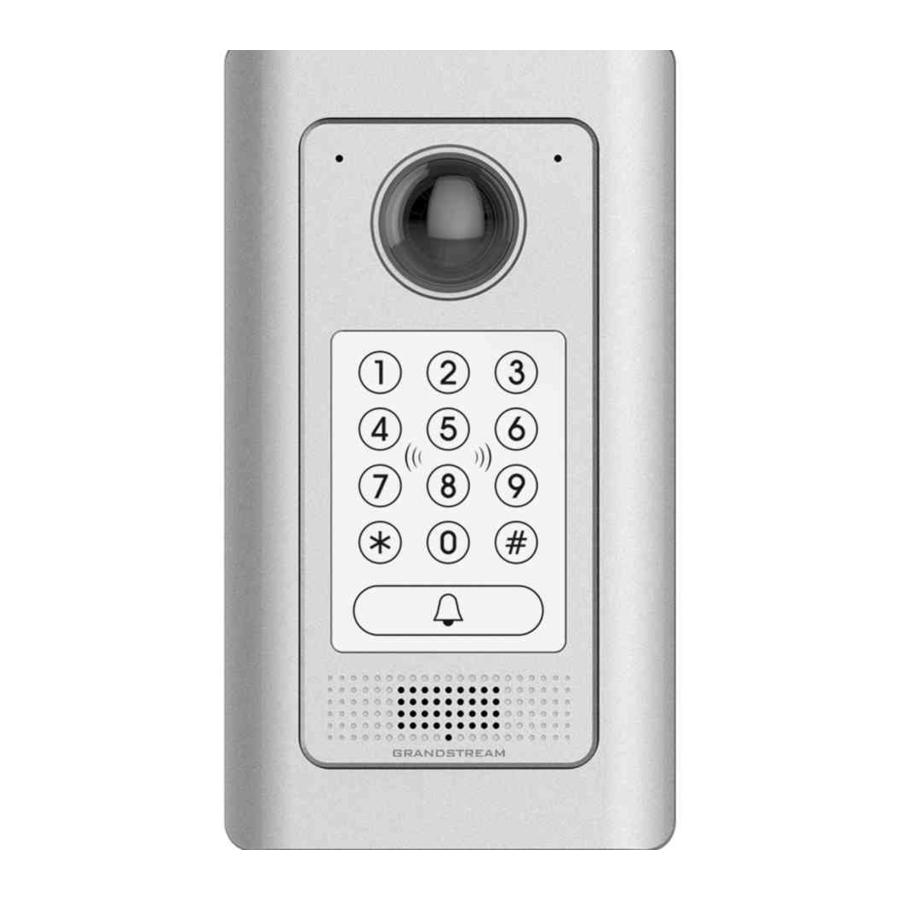
INTRODUCTION GDS3710 HD IP Video Door System is a hemispheric IP video door phone and a high-definition IP surveillance. GDS3710 is ideal for monitoring from wall to wall without blind spots. Powered by an advanced Image Sensor Processor (ISP) and state of the art image algorithms, it delivers exceptional performance in all lighting conditions. -
Page 5: Gds3710 Wiring Connection
GDS3710 WIRING CONNECTION The first step to setup the GDS3710 in an environment is to choose the powering method then and connect an RJ45 cable so it can interact with the network and start operating. Two ways are possible to power the... -
Page 6: Connecting Alarm In And Alarm Out Pins
GDS3710 trough (12V, GND). Connecting Alarm IN and Alarm OUT PINs The GDS3710 have two alarm input entries and two alarm output entries and a ground entry as shown in the following figure. -
Page 7: Figure 4: Back Cover 2
Figure 4: Back Cover 2 The following table summarizes the GDS3710 entries and their purpose. Jack Signal Function Note Orange / White Orange Data Green / White Ethernet Green PoE 802.3af Class 3, 12.95W Please twist these two wires PoE_SP2... -
Page 8: Alarm In Connection Example
3 party power supply is needed to power the device connected to the GDS3710 via Alarm IN or Alarm OUT. Alarm IN Connection Example Connect Alarm (IN1+, IN1-) or (IN2+, IN2-) to appropriate wires in order to receive signal from the third party device as shown below. -
Page 9: Alarm Out Connection Example
Connect Alarm (NO1, COM1) to appropriate wires in order to receive signal from the third party device as shown below. Figure 6: Alarm Output Example Note: Please refer to GDS3710 User Manual for information to detect and access the GDS web GUI. P a g e GDS3710 Input/output Alarms Configuration Guide... -
Page 10: Gds3710 Alarm Configuration
GDS3710 ALARM CONFIGURATION The below diagram illustrates an example of peripheral connections for the GDS3710. Figure 7: Peripheral Connections for GDS3710 P a g e GDS3710 Input/output Alarms Configuration Guide... -
Page 11: Alarm Schedule
To configure the Alarm IN/OUT on the GDS3710, access the webGUI, after detecting the GDS3710 IP address using one of the methods previously mentioned, and log in as admin (the default user/pass for admin log in is admin/admin). Navigate to “Alarm Config”, this tab contains four sub sections as shown below. -
Page 12: Figure 9: Alarm Schedule
Figure 9: Alarm Schedule GDS3710 supports up to 10 alarm schedules to be configured, with time span specified by users. User can edit the alarm schedule by clicking button. Usually the 24 hours’ span is 00:00 ~ 23:59, which is 24 hours’... -
Page 13: Alarm Action
When checked, the alarm video will be transferred to Alarm Center. Voice Alarm to SIP If the SIP server or the peer IP device is configured, check this will allow Phone the event to trigger alarm SIP call to pre-configured number. P a g e GDS3710 Input/output Alarms Configuration Guide... -
Page 14: Alarm Phone List
Once the event is triggered (Motion Detection, Door Bell Pressed…) the GDS3710 will call the first number, once time out is reached and no answer is returned from the first number, the GDS3710 will try the next number on the list and so on. Once the remote phone answers the call an alarm will be played to notify users that an event is triggered. -
Page 15: Figure 14: Events Page
Figure 14: Events Page Alarm can be triggered either by motion detection or by GDS3710 input. P a g e GDS3710 Input/output Alarms Configuration Guide... -
Page 16: Motion Detection
Select a zone on the screen then click on Clear to delete the region. Sensitivity Region sensitivity (value between 0-100%). Select Alarm Schedule Select the Schedule programmed. Select Alarm Action Profile Select the programmed Alarm Action. P a g e GDS3710 Input/output Alarms Configuration Guide... -
Page 17: Digital Input 1
Set the password for the hostage mode. Select Alarm Action Profile Select the Alarm action to be taken when the hostage password is typed on the GDS3710 keypad. Note: No sound alarm will be triggered in this mode. P a g e... -
Page 18: Tamper Alarm
Tamper Alarm Tamper alarm is anti-hack from Hardware level. When this option is checked, if the GDS3710 is removed from the installation board, it will generate the alarm actions configured. There is an embedded mechanism on the GDS3710 that allow it to sense when the it is removed.
Need help?
Do you have a question about the GDS3710 and is the answer not in the manual?
Questions and answers