Table of Contents
Advertisement
Advertisement
Table of Contents

Related Manuals for Grandstream Networks GSC35 Series


Summary of Contents for Grandstream Networks GSC35 Series
- Page 1 Grandstream Networks, Inc. GSC35XX Series User Manual...
- Page 2 Grandstream Networks, Inc. is not permitted. The latest electronic version of this guide is available for download here: http://www.grandstream.com/support Grandstream is a registered trademark and Grandstream logo is trademark of Grandstream Networks, Inc. in the United States, Europe and other countries. CAUTION Changes or modifications to this product not expressly approved by Grandstream, or operation of this product in any way other than as detailed by this guide, could void your manufacturer warranty.
- Page 3 FCC Caution Any Changes or modifications not expressly approved by the party responsible for compliance could void the user's authority to operate the equipment. This device complies with part 15 of the FCC Rules. Operation is subject to the following two conditions: (1) This device may not cause harmful interference, and (2) this device must accept any interference received, including interference that may cause undesired operation.
- Page 4 CE Authentication Hereby, Grandstream Networks, Inc. declares that the radio equipment GSC3510/GSC3505 is in compliance with Directive 2014/53/EU. The full text of the EU declaration of conformity is available at the following internet address: http://www.grandstream.com/support/resources/ P a g e GSC35XX Series User Manual...
- Page 5 GNU GPL INFORMATION GSC3510/GSC3505 firmware contains third-party software licensed under the GNU General Public License (GPL). Grandstream uses software under the specific terms of the GPL. Please see the GNU General Public License (GPL) for the exact terms and conditions of the license. Grandstream GNU GPL related source code can be downloaded from Grandstream web site from: http://www.grandstream.com/sites/default/files/Resources/GSC35XX_gpl.zip P a g e...
-
Page 6: Table Of Contents
Table of Contents DOCUMENT PURPOSE ....................11 CHANGE LOG ......................12 Firmware Version 1.0.0.15 ........................12 WELCOME ........................13 PRODUCT OVERVIEW ....................14 Feature Highlights ........................... 14 GSC3510/GSC3505 Technical Specifications..................14 GETTING STARTED ..................... 16 Equipment Packaging..........................16 GSC3510/GSC3505 Ports ........................17 GSC3510/GSC3505 LED Indicators ....................... - Page 7 Network Status ............................. 34 System Info ............................35 Account Page Definitions ........................35 General Settings ..........................35 SIP Settings ............................38 Codec Settings ............................. 42 Call Settings ............................44 Advanced Settings ..........................46 Calls Page Definition ..........................48 Call ............................... 48 Call History ............................
- Page 8 Security Settings ..........................72 Preferences ............................73 TR-069 ..............................73 Sensor Settings ............................ 74 Backup ..............................75 Maintenance Page Definitions ......................... 76 Upgrade ............................... 76 System Diagnosis ..........................80 Event Notification ..........................82 Application Page Definitions ........................83 LDAP Book............................83 Recording .............................
- Page 9 Table of Tables Table 1: GSC3510/GSC3505 Features in a Glance ................... 14 Table 2: GSC3510/GSC3505 Technical Specifications................14 Table 3: Equipment Packaging ........................16 Table 4: GSC3510/GSC3505 Ports Description ..................17 Table 5: GSC3510 LED Indicators ......................17 Table of Figures Figure 1: GSC3510/GSC3505 Package Content..................
- Page 10 Figure 30: Trigger Time ..........................33 Figure 31: Click-to-Dial Feature ........................48 Figure 32: Outgoing call in progress and accepted ..................49 Figure 33: Call History All ........................... 50 Figure 34: Call details under Call History All ....................50 Figure 35: Add number from call history to an existing contact ..............51 Figure 36: Call History Intercept Record ....................
-
Page 11: Document Purpose
DOCUMENT PURPOSE This document describes how to configure the GSC3510 via web UI menu to fully manipulate device's features. Please visit http://www.grandstream.com/support to download the latest “GSC3510 User Manual”. This guide covers following topics: Product Overview ▪ ▪ Getting Started ▪... -
Page 12: Change Log
CHANGE LOG This section documents significant changes from previous versions of user manual for GSC35XX Seies. Only major new features or major document updates are listed here. Minor updates for corrections or editing are not documented here. Firmware Version 1.0.0.15 •... -
Page 13: Welcome
WELCOME Thank you for purchasing Grandstream GSC3510/GSC3505 SIP Intercom speakers. The GSC3505 is a one-way SIP Intercom Speaker and GSC3510 is a two-way full-duplex SIP intercom speaker/microphone, both featuring one 100Mbps Ethernet port with PoE/PoE+, integrated dual-band 2.4G/5G Wi-Fi, integrated Bluetooth, high fidelity 8W speaker and a multi-purpose input port supporting a wide range of peripherals, 3 directional microphones with Multichannel Microphone Array Design (MMAD) available for GSC3510 only. -
Page 14: Product Overview
PRODUCT OVERVIEW Feature Highlights The following table contains the major features of the GSC3510/GSC3505: Table 1: GSC3510/GSC3505 Features in a Glance • Up to 16 SIP accounts. GSC3510 • Ethernet RJ45 10/100Mbps, PoE/PoE+, Integrated Bluetooth, Wi-Fi. GSC3505 • Both GSC3505 and GSC3510 HD with their Hi-Fi speaker delivers full-band audio, Hands-free speakerphone with HD acoustic chamber, advanced acoustic echo cancellation, while GSC3510 adds a state-of-art microphone array with pickup distance up to 4.2 meters. - Page 15 Hold, transfer, forward (unconditional/no-answer/busy), call park/pickup, Telephony Features downloadable contacts, call record, call log, auto answer, click-to-dial, flexible dial plan. HD Audio Yes, HD speakerphone with support for wideband audio. Layer 2 QoS (802.1Q, 802.1p) and Layer 3 (ToS, DiffServ, MPLS) QoS. Security User and administrator level passwords, MD5 and MD5-sess based authentication, 256-bit AES encrypted configuration file, TLS, SRTP, HTTPS, 802.1x media access...
-
Page 16: Getting Started
GETTING STARTED This chapter provides basic installation instructions including the list of the packaging contents and also information for obtaining the best performance with the GSC3510/GSC3505. Equipment Packaging Table 3: Equipment Packaging GSC3510/GSC3505 • 1x GSC3510/GSC3505 Main Case. • 1x Metal Bracket. •... -
Page 17: Gsc3510/Gsc3505 Ports
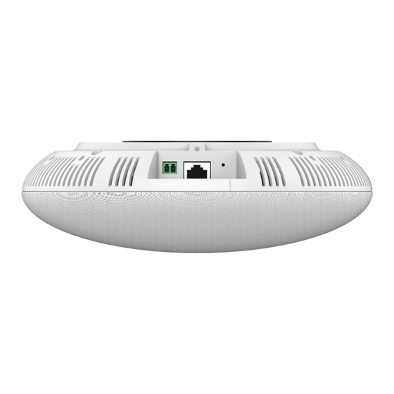
GSC3510/GSC3505 Ports Figure 2: GSC3510/GSC3505 Ports Table 4: GSC3510/GSC3505 Ports Description Name Description Factory reset button. Press for 10 seconds to reset factory default RESET settings. NET/PoE Ethernet RJ45 port (10/100Mbps) supporting PoE/PoE+. 2-PIN Port 2-PIN Multi-Purpose Input Port. GSC3510/GSC3505 LED Indicators The GSC3510/GSC3505 contains 4 types of colored LEDs (Red, Green, White and Blue light) that are used in some specific situations and operations. -
Page 18: Hardware Installation
Hardware Installation GSC3510/GSC3505 can be mounted on the wall or ceiling. Please refer to the following steps for the appropriate installation Wall Mount 1. Locate the equipment holder on the desired position with arrow up. Drill three holes on the wall referring to the positions of holes on the metal bracket. -
Page 19: Ceiling Mount
Ceiling Mount 1. Put the ceiling mounting (metal bracket) in the ceiling’s center and mark the position of the three screws holes. 2. Drill a round hole with a diameter of 18mm for Ethernet cable. The distance between its center and the highlighted hole on the plastic bracket should be 35mm. -
Page 20: Anti-Theft Installation
Anti-theft Installation After the device is assembled with the metal bracket support on the wall or ceiling, use the anti-detachable screw (M3x15) in order to prevent theft. Figure 11: Anti-theft Installation Powering and Connecting GSC3510/GSC3505 The GSC3510/GSC3505 can be powered on using PoE/PoE+ switch or PoE injector using following steps: •... -
Page 21: Connecting Wiring Seat
Connecting Wiring Seat GSC3505/GSC3510 support to connect a “Key & LED” or “Normal Key” to the 2-pin port via Wiring Seat using following steps: • Step 1: Take the wiring seat from the install kits. • Step 2: Connect the “Key & LED” or “Normal Key” with the wiring seat (as shown in the figure below) Note: This port supports the parallel connection of an incandescent lamp (with less than 1W) or an LED lamp (with less than 100mA). -
Page 22: Figure 14: Gsc3510 Web Gui - Login
Figure 14: GSC3510 Web GUI – Login Users can use a computer connected to the same network as the GSC3510/GSC3505 to discover and access the GSC3510/GSC3505 Configuration Interface using its MAC Address. Please, refer to the following steps in order to access the GSC3510/GSC3505 Web GUI: 1. -
Page 23: Gsc3510/Gsc3505 Application Scenarios
GSC3510/GSC3505 APPLICATION SCENARIOS GSC3510/GSC3505 SIP Two-Way/One-Way Intercom System GSC3510/GSC3505 can be used as an Intercom System using built-in SIP accounts, once the SIP account registered the device can receive paging/intercom calls and it will automatically answer calls coming from whitelisted numbers. Note: GSC3505 is SIP one-way Intercom, while GSC3510 is two-way Intercom. -
Page 24: Figure 16: Sip Account Configuration
Figure 16: SIP Account Configuration Once the account registered correctly, the GSC3510/GSC3505 will show the account status as “Registered” under Status → Account Status. Figure 17: SIP Account Status By default, the GSC3510/GSC3505 Blocks non-whitelisted number under Calls → Black/White List Settings →... -
Page 25: Figure 18: Default Blocking Rules
Figure 18: Default Blocking Rules On the screenshot below, only number 1001 is allowed to call GSC3510/GSC3505: Figure 19: Whitelisted Devices As soon as a SIP call is received by the GSC3510/GSC3505, it first checks if the Caller ID number is allowed on the Whitelist and then answers automatically. -
Page 26: Multicast Paging Application
Multicast Paging Application Multicast paging is an approach to let different SIP users to listen for paging calls from a common multicast IP address. In multicast page call, an audio connection will be set up from sender to receiver, but the receiver will be only able to receive audio, a one-way communication. -
Page 27: Figure 21: Multicast Paging Listening Addresses
Figure 21: Multicast Paging Listening Addresses In above screenshot, Listening Address “237.11.10.11:6767” with label “Sales” has the highest priority. Users can enable “Paging Priority Active” option (under Multicast Paging tab) to accept incoming paging calls during active multicast paging. The paging call with higher priority than active one will be accepted. Figure 22: Multicast Paging –... -
Page 28: Figure 23: Multicast Paging - Priority Barge
In the case of receiving a multicast paging call while on a unicast SIP call, the GSC3510/GSC3505 can choose to either keep the SIP call or to hold this last and allow the multicast call depending on paging call priority. This is can be set using “Paging Barge”... -
Page 29: Bluetooth Speaker
Bluetooth Speaker The GSC3510/GSC3505 can be used as a Bluetooth speaker for another device and it needs to be connected via Bluetooth to that device. Users need to turn on GSC3510/GSC3505’s Bluetooth function first. The first time when using a new Bluetooth device with the GSC3510/GSC3505, "pair" the device with GSC3510/GSC3505 so that both devices know how to connect securely to each other. -
Page 30: 2-Pin Multi-Purpose Input Applications
2-pin Multi-Purpose Input Applications GSC3510/GSC3505 supports 2-pin multi-purpose input that can connect a “Key with LED” or “Normal Key”. By configuring the sensor settings users can enable the GSC3510/GSC3505 to play an audio file (.wav/.mp3 format), trigger a SIP call to a pre-configured extension, or to start recording audio locally when triggered. -
Page 31: Figure 27: Sensor Setting - Linkage Function
Under Basic Setting section, users can set “Sensor Type” and “Trigger Type”. Two states are supported by the Input circuit for the “Sensor Type”: 1. Normally Open where the contact is disconnected when there is no electricity 2. Normally Close where the contact is connected when there is no electricity. Users could set “Trigger Type”... -
Page 32: Figure 28: Sensor Setting - Linkage Function - Play Audio
Figure 28: Sensor Setting - Linkage Function - Play Audio • Make Call: If checked, GSC3510/GSC3505 will dial out configured numbers on “Dial out extension” fields (up to 2 numbers supported). Figure 29: Sensor Setting - Linkage Function - Make Call •... -
Page 33: Figure 30: Trigger Time
The alarm can be configured to be triggered all the time or based on a specific schedule that can be configured under System Settings → Sensor Settings → Trigger Time as shown on below picture; the alarm actions will be triggered based on the configured schedule: Figure 30: Trigger Time P a g e GSC35XX Series User Manual... -
Page 34: Gsc3510/Gsc3505 Web Gui Settings
GSC3510/GSC3505 WEB GUI SETTINGS The GSC3510/GSC3505 embedded Web server responds to HTTP/HTTPS GET/POST requests. Embedded HTML pages allow users to configure the application phone through a Web browser such as Microsoft’s IE, Mozilla ,Firefox, Google Chrome and etc. Status Page Definitions Account Status Account 16 SIP accounts on the device. -
Page 35: System Info
System Info Product Model Product model of the device: GSC3510/GSC3505. Hardware Revision Hardware version number. Part Number Product part number. System Version Firmware version ID. This is the main software release version, which is used to identify the software system of the device. Recovery Version Recovery image version. - Page 36 • Disabled: Will use “SIP User ID” information in the Request-Line and “From” header. • User=Phone: “User=Phone” parameter will be attached to the Request-Line and “From” header in the SIP request to indicate the E.164 number. If set to "Enable". •...
- Page 37 On this mode, the device will resolve DNS SRV records and tries to send the request to the server having lowest priority and if it doesn’t respond, it will move on to the next IP until one of the servers responds, once this happen the device will keep contacting this responding IP until DNS timeout (30 minutes) before starting over.
-
Page 38: Sip Settings
SIP Settings SIP Basic Settings SIP Registration Allows the device to send SIP REGISTER messages to the proxy/server. The default setting is "Yes". Unregister before New Controls whether to clear SIP user’s information by sending un-register Registration request to the proxy server. •... - Page 39 SIP OPTIONS Keep Alive Configures the time interval when the device sends OPTIONS message to Interval (s) SIP server. The default value is 30 seconds, in order to send an OPTIONS message to the server every 30 seconds. The default range is 1-64800. SIP OPTIONS Keep Alive Configures the maximum times of sending OPTIONS message Maximum Tries...
- Page 40 Use Actual Ephemeral Determines the port information in the Via header and Contact header of Port in Contact with SIP message when the device use TCP or TLS. If set to No, these port TCP/TLS numbers will use the permanent listening port on the device. Otherwise, they will use the ephemeral port for the particular connection.
- Page 41 Min-SE (s) Determines the minimum session expiration timer (in seconds) if the device act as a timer refresher. Default is 90. The valid range is from 90 to 64800. UAC Specify Refresher Sets which party will refresh the active session if the device makes outbound calls.
-
Page 42: Codec Settings
Codec Settings Preferred Vocoder Preferred Vocoder Lists the available and enabled Audio codecs for this account. Users can enable the specific audio codecs by moving them to the selected box and set them with a priority order from top to bottom. This configuration will be included with the same preference order in the SIP SDP message. - Page 43 Enable Audio RED with If set to "Yes", FEC will be enabled for audio call. The default setting is "No". Audio FEC Payload Type Configures audio FEC payload type. The valid range is from 96 to 127. The default value is 121. Audio RED Payload Configures audio RED payload type.
-
Page 44: Call Settings
Enable SRTP Key Life Defines the SRTP key life time. When this option is set to be enabled, Time during the SRTP call, the SRTP key will be valid within 2 SIP packets, and phone will renew the SRTP key after this limitation. The default setting is “Yes”. - Page 45 Refer-To Use Target Sets the device to use the target’s Contact header tag to the Refer-To Contact header in the SIP REFER message during an attended transfer. The default setting is “No”. Dial Plan Dial Plan Prefix This parameter can be configured to define the prefix added to each dialed number.
-
Page 46: Advanced Settings
Block any number of leading digits 1900 or add prefix 1617 for any dialed 7-digit numbers • Example 3: {1xxx[2-9]xxxxxx | <2=011>x+} Allow any number with leading digit 1 followed by a 3-digit number, followed by any number between 2 and 9, followed by any 7-digit number OR allow any length of numbers with leading digit 2, replacing the 2 with 011 when dialed. - Page 47 Validate Incoming SIP Specifies if the device will check the incoming SIP messages caller ID and Messages CSeq headers. If the message does not include the headers, it will be rejected. The default setting is "No". Allow Unsolicited It is used to configure whether to dial the number carried by Refer-to after REFER receiving SIP REFER request actively.
-
Page 48: Calls Page Definition
Advanced Features Virtual Account It is used to set to categorize accounts in server mode groups, the accounts Group in the same group will be combined as one and the account widget will display the Caller ID in the account with lowest ID. The device can answer any incoming calls to each account in groups. -
Page 49: Call History
Once the number / IP address is dialed or a Call is received, a window pops up showing the call information and gives the user the ability to do the following operations: Figure 32: Outgoing call in progress and accepted : Reduce the window to a bar at the top of Web GUI interface. -
Page 50: Figure 33: Call History All
Figure 33: Call History → All By Tapping on the checkbox to select the call history entries, users can do the following operations: • Delete Call History: Users need to press the button after selecting the call history entries. • Add entries to Whitelist: Users may select the entries to be allowed to call the GSC3510/GSC3505 by clicking on the button after selecting the right entries. -
Page 51: Call History → Intercept Record
From the Call details window, users can also add the number selected to local contacts by creating a new contact , or by adding it to an existing contact • Add number to an existing contact: Users can click on “Save to local contacts” in order to show a window with all the contacts already registered in the GSC3510/GSC3505 local contacts and to choose one of the contacts to link the selected number with: Figure 35: Add number from call history to an existing contact... -
Page 52: Figure 37: Call Details Under Call History Intercept Record
By checking the checkbox to select entries, users can do the following operations: • Delete Blocked Numbers Call History: Users need to press the button after selecting the call history entries. • Add entries to Whitelist: Users may select the blocked entries to give them permission to call the GSC3510/GSC3505 by clicking on the button after selecting the right entries. -
Page 53: Contacts
Contacts Contacts section is divided into two sections: “Contacts List” and “Group”. Contacts List Figure 38: Contacts → Contacts List • Dial Contact (Available for GSC3510 only). • Edit contact details. • : Users can select one or a bench of contacts and click on the “Delete” button order to delete all the selected contacts. - Page 54 • : Users need to click on the “More” button for more operations (Import contacts, Export contacts, Download contacts). Import Contacts Clear The Old List Determines if the device will delete the previous contacts when a new contact file is imported. If set to "Yes", the previous contacts will be removed.
- Page 55 File Type Sets the type format for contacts file importing. It can be selected from the dropdown list. • • vCard The default setting is "XML". Import Local File Uploads the contact files from PC to the device. Export Contacts File Encoding Specifies the encoding format for contacts file exporting.
- Page 56 Replace Duplicate Items Keeps the original contact entries when duplicated contact entries are included in the contact file. If set to "Yes", the device will replace the original entries to the new one. Otherwise, the device will save both contact entries. The default setting is "No".
-
Page 57: Group
Automatic Download Determines how the device to send the request to the server to download Interval the contacts file. It can be selected from the dropdown list: • None • 2 Hour • 4 Hour • 6 Hour • 8 Hour •... -
Page 58: Black/White List Settings
Figure 41: Add New Group Black/White List Settings This section is for managing calling permissions to the GSC3510/GSC3505. Users can give or remove the permission to call the GSC3510/GSC3505, this can be managed under the following three subsections: Whitelist Users can specify the numbers allowed to call the GSC3510/GSC3505 and every time a number is added it is listed in the below list: Figure 42: Whitelist section •... -
Page 59: Figure 43: Add Phonebook Contacts To Whitelist
• : Users can add the phonebook contacts to the whitelist by clicking on “Add from contacts” button. A window pops up showing the existing contacts so that users can select the ones wishing to give permission to. Figure 43: Add phonebook contacts to whitelist •... -
Page 60: Blacklist
Figure 45: Add Manually to Whitelist Note: Users can modify the name of the number listed in the Whitelist by clicking on Blacklist Users can specify the numbers to be blocked by the GSC3510/GSC3505 for incoming calls, and every time a number is added to the blacklist, it is listed in the below list: Figure 46: Blacklist Section •... -
Page 61: Blocking Rules
Figure 47: Add from Call History to Blacklist • : Users can add numbers manually to blacklist by clicking on “Add manually” button. A window pops up allowing users to enter the number and its name (Please, refer to Figure 25). Note: Users can modify the name of the number listed in the blacklist by clicking on Blocking Rules This sub-section allows the user to define the blocking rules for Non-white list calls. -
Page 62: Call Settings
Keep-alive Interval (s) Specifies how the device will send a Binding Request packet to the SIP server in order to keep the “ping hole” on the NAT router to open. The default setting is 20 seconds. The valid range is from 10 to 160. STUN Server Configures the URI of STUN (Simple Traversal of UDP for NAT) server. -
Page 63: Ring Tone
Virtual Account Group If set to "Yes", when processing SIP Register 3XX Response, it will parse Avaya Mode the address site in 3XX, modify the account server info "SIP Server: port" & "SIP Transaction" in virtual account group and initiate registration again. This feature is designed for the Avaya customers. -
Page 64: Multicast Paging
Call Progress Tones: Configures tone frequencies according to user preference. By default, the • Dial Tone tones are set to North American frequencies. Frequencies should be • Second Dial Tone configured with known values to avoid uncomfortable high pitch sounds. •... -
Page 65: Network Settings Page Definitions
Network Settings Page Definitions Ethernet Settings Preferred Internet If IPv4 is selected, the device will be using IPv4 addressing, otherwise, it Protocol will be using IPv6 addressing. Default is Prefer IPv4. Different Networks for Configures whether to set up different networks for the phone data and the Data and VoIP Calls call. - Page 66 Option 133 encapsulated. In this case, please make sure the option “Allow DHCP Option 43 and Option 66 to Override Server” is enabled under GSC3510/GSC3505 web UI → Maintenance → Upgrade. By default, it is set to “Encapsulated in DHCP Option 43”: Host name (Option 12) Sets the name of the client in the DHCP request.
-
Page 67: Bluetooth
802.1x Identity Enters the identity information for the selected 802.1x mode. (This setting will be displayed only if 802.1 X mode is enabled). 802.1x Secret Enters the secret for the 802.1x mode. This option will appear when 802.1x mode is EAP-MD5 or EAP-PEAP. CA Certificate Uploads the CA Certificate file to the device. -
Page 68: Figure 48: Wi-Fi Basics Page
Figure 48: Wi-Fi Basics Page 4. Identify the Wi-Fi network’s SSID and click on “Connect”, then enter the correct password information to connect to the selected network: Figure 49: Connect to Wi-Fi Network 5. Users can check the Wi-Fi parameters and change the setting by checking the “Show advanced options”... -
Page 69: Wi-Fi Settings Description
Figure 50: GSC3510/GSC3505 Connect to Wi-Fi-Show Advanced Options Wi-Fi Settings description Wi-Fi Basics Wi-Fi Function Enables/disables the Wi-Fi feature. The default setting is "Disable". Permits to scan and select the available Wi-Fi networks within the range if ESSID the Wi-Fi feature is enabled. Click on "Connect" to select the Wi-Fi network and to enter the needed password if it is required. -
Page 70: Openvpn® Settings
OpenVPN® Settings OpenVPN ® Settings Enable OpenVPN® This enables/disables OpenVPN® functionality, and requires the user to have access to an OpenVPN® server. The default setting is No. Note: To use OpenVPN® functionalities, users must enable OpenVPN® and configure all of the settings related to OpenVPN®, including server address, port, OpenVPN®... -
Page 71: Advanced Network Settings
Advanced Network Settings Advanced Network Settings Preferred DNS 1 Sets the preferred DNS server 1 for the user. Preferred DNS 2 Sets the preferred DNS server 2 for the user. Enable LLDP Enables the LLDP (Link Layer Discovery Protocol) feature on the device. If it is set to “Yes”, the device will broadcast LLDP PDU to advertise its identity and capabilities and receive same from a physical adjacent layer 2 peer. -
Page 72: System Settings Page Definitions
System Settings Page Definitions Security Settings Web/SSH Access Enable SSH Enables/disables SSH access to the device. The default setting is "Yes". SSH Port Customizes the SSH port. By default, SSH uses port 22. Access Method Determines which protocol will be used to access the device ‘s Web GUI. It can be selected from HTTP and HTTPS. -
Page 73: Preferences
User Certificate Add User Certificate Allows to upload & Install User Certificate file to phone. User Certificates Lists Users Certificates previously uploaded. Administrator can delete a certificate from here. Custom Certificate Import Custom Allows to upload & Install Custom Certificate file to device. Certificate Custom Certificate Lists Custom Certificates previously uploaded. -
Page 74: Sensor Settings
Connection Request Enters password for the ACS to connect to the device. Password Connection Request Enters the port for the ACS to connect to the device. Port CPE Cert File Uploads Cert File for the device to connect to the ACS via SSL. CPE Cert Key Uploads Cert Key for the device to connect to the ACS via SSL. -
Page 75: Backup
Backup GSC3510/GSC3505 Backup page is used to back up data or import backup files to restore data. Users can start the Backup by clicking on “Start Backup”. Figure 51: GSC3510/GSC3505 Backup Page The following data on the GSC3510/GSC3505 can be backed up and restored to the device again using the built-in Backup application: Contacts, Call history, Configuration information. -
Page 76: Maintenance Page Definitions
Figure 53: Generated Backup By generating the Backup, users can do the following operations: • : Users can bring back to the GSC3510/GSC3505 all the backup contents selected during Back generating operation by clicking on “Restore”. • : Users can delete the generated Backup by clicking on “Delete”. •... - Page 77 Firmware File Prefix Checks if firmware file is with matching prefix before downloading it. This field enables user to store different versions of firmware files in one directory on the firmware server. Firmware File Postfix Checks if firmware file is with matching postfix before downloading it. This field enables user to store different versions of firmware files in one directory on the firmware server.
- Page 78 XML Config File Decrypts XML configuration file when encrypted. The password used for Password encrypting the XML configuration file is using OpenSSL. Download Device Downloads the device's configuration file in text format. The config file Configuration includes all the P value parameters for phone's current settings except password for security purpose.
- Page 79 DHCP Option 120 Configures the device to allow the DHCP offer message to override the Override SIP Server Config Server Path via the Option 120 header. The default setting is "Yes". Note: Reboot the device to make changes take effect. Allow DHCP Option 242 Enables DHCP Option 242.
-
Page 80: System Diagnosis
System Diagnosis Syslog Syslog Protocol Select the transport protocol over which log messages will be carried. • UDP: Syslog messages will be sent over UDP. • SSL/TLS: Syslog messages will be sent securely over TLS connection. Configures the URI which the device will send the syslog messages to. The Syslog Server default setting is "log.ipvideotalk.com". - Page 81 Debug One-click Debugging One-click Debugging Capture the checked info in the debugging list, click "Start" to debug if including "Capture trace" item and click "Stop" to end, Click "Capture" in another situation. All retrieved files will be generated to a package, and the last package will be overwritten, while the trace file will stay remain.
-
Page 82: Event Notification
Ping Target Host The IP address or URL for the Target Host of the Ping. Press Start to send traceroute request to configured target host. Press Stop to end traceroute running process. NSLookup Hostname Enter a host name and find out the corresponding IP address. It will also do reverse name lookup and find the host name for an IP address you specify. -
Page 83: Application Page Definitions
On Attended Transfer Configures the event URL when users transfer a call with attended transfer on the device. Log On Configures the event URL when users log on the device successfully. Log Off Configures the event URL when users log off the device. On Register Configures the event URL when an account in the device is registered successfully. -
Page 84: Recording
LDAP Mail Attributes Determines the "mail" attributes of each record which are returned in the LDAP search result. Example: mail LDAP Name Filter Configures the filter used for name lookups. Examples: (|(cn=%)(sn=%)) returns all records which has the "cn" or "sn" field starting with the entered prefix;... -
Page 85: Device Detection Page Definitions
Delete, Modify, lock or download the recording file. Notes: Operation • A recording file cannot be deleted if it is locked. • Users can delete a bench of recording files by clicking on “Delete”. Device Detection Page Definitions Audio Loop Test Available for the GSC3510 only Audio loop test is used to test the three MICs available on the GSC3510. -
Page 86: Led Test
Figure 55: Device Detection - Built-in Speaker Test LED Test Led Test is used to test the availability of the four colored LEDs and their intensity. The colors of LEDs available on the GSC3510/GSC3505 are: Green, Red, Blue and White. Figure 56: Device Detection - LED Test P a g e GSC35XX Series User Manual... -
Page 87: Certificate Verify
Certificate Verify Certificate Verify is used to test the validity of the existing certificate. Reset Button Test Reset Button Test is used to test the Reset button, during the test the reset button doesn’t trigger factory reset, this feature allows the user to check if the button is responding. Figure 57: Device Detection - Reset Button Test P a g e GSC35XX Series User Manual... -
Page 88: Experiencing The Gsc3510/Gsc3505
EXPERIENCING THE GSC3510/GSC3505 Please visit our website: http://www.grandstream.com to receive the most up- to-date updates on firmware releases, additional features, FAQs, documentation and news on new products. We encourage you to browse our product related documentation, FAQs User and Developer Forum for answers to your general questions.
Need help?
Do you have a question about the GSC35 Series and is the answer not in the manual?
Questions and answers