
Related Manuals for Taylor PH61


Summary of Contents for Taylor PH61
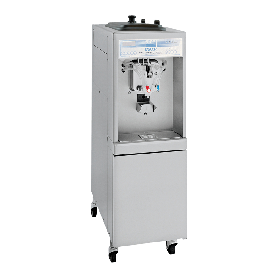
- Page 1 OPERATOR’S MANUAL Model PH61 Heat Treatment Peristaltic Pump Shake Freezer Original Operating Instructions 2006 (Original Publication) 048119TS (Updated 10/29/2019)
- Page 2 Note: Only instructions originating from the factory or its authorized translation representative(s) are considered to be the original set of instructions. © 2006 Taylor Company (Updated 10/29/2019) 048119TS Any unauthorized reproduction, disclosure, or distribution of copies by any person of any portion of this work may be...
-
Page 3: Table Of Contents
Model PH61 ........ - Page 4 Table of Contents Section 6: Operating Procedures Machine Setup ............6-1 Sanitizing .
-
Page 5: Section 1: To The Installer
Taylor machines. operate indoors, under normal ambient temperatures of • Only Taylor service personnel should perform 70°F to 75°F (21°C to 24°C). The machine has installation, maintenance, and repairs on Taylor successfully performed in high ambient temperatures of machines. -
Page 6: Air-Cooled Machines
Please contact your local authorities if you have any (code designation 60245 IEC 57) installed with questions. the proper cord anchorage to relieve conductors from strain, including twisting, at the terminals Each machine requires one power supply for each data To the Installer PH61 Peristaltic Pump... -
Page 7: Beater Rotation
If the supply cord is damaged, it must be replaced by a WARNING! Refrigerant liquid sprayed onto the Taylor service technician to avoid a hazard. skin may cause serious damage to tissue. Keep eyes and skin protected. If refrigerant burns should occur, Beater Rotation flush the area immediately with cold water. - Page 8 TO THE INSTALLER Notes: To the Installer PH61 Peristaltic Pump...
-
Page 9: Section 2: To The Operator
During the Heat Treatment process, the product is The Model PH61 will not compensate and correct for any brought to a temperature sufficient to destroy bacteria errors during the setup or filling operations. Thus, the and is returned to a standby temperature. -
Page 10: Compressor Warranty Disclaimer
It should also be noted that Taylor does not warrant the refrigerant used in its machine. For example, if the refrigerant is lost during the course of ordinary service to... -
Page 11: Section 3: Safety
Safety Section 3 We at Taylor are concerned about the safety of operators at all times when they are coming in contact with the machine and its parts. Taylor makes every effort to WARNING! Avoid injury. design and manufacture built-in safety features to protect •... - Page 12 USE EXTREME CAUTION when removing blades that are very sharp. excess product is removed from the pitcher to eliminate product carryover. Failure to follow this instruction may result in contaminated product or personal injury from blade contact. Safety PH61 Peristaltic Pump8...
- Page 13 height of 63 in. (1.6 m) from the floor. 70°F to 75°F (21°C to 24°C). The machine has successfully performed in high ambient temperatures of up to 104°F (40°C) at reduced capacities. Safety PH61 Peristaltic Pump8...
- Page 14 SAFETY Notes: Safety PH61 Peristaltic Pump8...
-
Page 15: Model Ph61
Operator Parts Identification Section 4 Model PH61 Figure 4-1 Operator Parts Identification PH61 Peristaltic Pump... - Page 16 OPERATOR PARTS IDENTIFICATION Model PH61 Parts Identification List Item Description Part No. Item Description Part No. Kit A.-Cover-Hopper X65369 Fastener-Clip 1/4-20 U 045865 Agitator X44797 Caster-4" SWV 5/8 Stem w/Brake 034081 Pump A.-Mix Simplified Shake X57028-14 Door A.-Syrup Cabinet X45325...
-
Page 17: Beater And Door Assembly
OPERATOR PARTS IDENTIFICATION Beater and Door Assembly Figure 4-2 Operator Parts Identification PH61 Peristaltic Pump... - Page 18 O-ring-11MM ID x 2MM W Green 053890 Pin A.-Pivot X22820 *18c Tool-Seal Install-Remove 035460 Handle-Draw Valve 034003 Retainer-Valve Pin *TTS* 054690 Valve A.-Draw-Aluminum X42210 Retainer-Syrup Valve *TTS* Metal 054554 *Not Shown O-ring-1-1/16 OD x.139W 020571 Operator Parts Identification PH61 Peristaltic Pump...
-
Page 19: X57028-Xx Pump A. - Mix Simplified
O-ring-PKG *25 to Bag* 008904 Cap-Valve Body Shake 056873-14 Clip-Retainer-Mix Pump 044641 Gasket-Simplified Pump Valve 053527 Tube A.-Feed-Hopper- Shake X56522 Adaptor-Mix Inlet-Shake- Blue 054944 Ring-Check-Feed-Tube 056524 O-ring-PKG *50 to Bag* 016132-SER Sleeve A.-Mix Pump X44761 Pin-Cotter-Hairpin-1/8DIA 044731 Operator Parts Identification PH61 Peristaltic Pump... -
Page 20: Accessories
OPERATOR PARTS IDENTIFICATION Accessories Apply the appropriate Taylor approved food safe lubricant. Figure 4-4 Item Description Part No. Item Description Part No. Tool-Seal Install- Remove 035460 Kit A.-Parts Tray Simp Pump X58447 (Consists of 044118 and 056525) Lubricant-Taylor Hi-Perf 048232 Kit A.-Tune Up SMP Pump... -
Page 21: Syrup Valve
Plunger-Syrup Valve w/Seals 053874-009 Ferrule- .625 ID Brass 053036 O-ring-Syrup Valve Plunger L 053874-007 Tube-Twinned Syrup 054580-86 Plunger-Syrup 053874-002 Kit A.-Repair Valve 054595 *Not Shown O-ring-Syrup Valve Plunger S 053874-006 Seal-Syrup Valve Plunger 053874-008 Operator Parts Identification PH61 Peristaltic Pump... -
Page 22: Brush A.-Package-Ht X44127
1"D x 2"LG x 14 Brush-Set LVB 050103 Brush-Double End 013072 Brush-End-Door-Spout 039719 Brush-Draw Valve 013073 Brush-Mix Pump Body- 3" x 7" 023316 1"OD x 2"x17" Brush-Pump Spout 054068 Brush-Draw Valve 014753 1-1/2"OD x 3" Operator Parts Identification PH61 Peristaltic Pump... -
Page 23: Section 5: User Interface
=MIX LOW To better communicate in the international arena, the words on many of our operator switches and buttons have symbols to indicate their functions. Your Taylor =MIX OUT machine is designed with these international symbols. The following chart identifies the symbol definitions used =HEAT MODE on the operator switches. -
Page 24: Power Switch
Heat cycle. If the beater motor is turning properly, press the WASH key to cancel the cycle. Press the AUTO key to resume normal operation. If the machine shuts down again, contact a Taylor service technician. User Interface PH61 Peristaltic Pump... -
Page 25: Operating Screen Descriptions
BRUSH CLEAN ON: 10/31 brush-cleaning are met and the 5 minutes expire, the screen will change to the second screen, which is the standard POWER SWITCH OFF screen. POWER SWITCH OFF TIME: 4:40 HOPPER: 62.1 BARREL: 67.7 User Interface PH61 Peristaltic Pump... - Page 26 Failure to follow these guidelines will cause the control to lock the freezer out of the Auto mode. Press the WASH key. The entire Heat Treatment cycle must be completed in 4 hours. User Interface PH61 Peristaltic Pump...
- Page 27 Heat cycle failure not due to a thermistor failure.) If the WASH key is pressed, the next display will appear NO HEAT TREAT START and the freezer will have to be disassembled and BECAUSE brush-cleaned. VARIABLE MESSAGE PRESS SEL KEY User Interface PH61 Peristaltic Pump...
-
Page 28: Operator Menu
HOPPER TEMP: 41.0F 4. COMP ON TOO LONG—Place the power switch in FREEZER LOCKED the OFF position. Call a Taylor service technician. Clear the tone. 5. HOPPER THERM BAD—Place the power switch in Once the freezer is unlocked by starting a Heat the OFF position. - Page 29 J F M A M J J A S O N D - < > - Pressing the arrow keys moves the cursor. Pressing the SEL key while under DISABLE accepts the selection and returns to the OPERATOR MENU. User Interface PH61 Peristaltic Pump...
- Page 30 SOFTWARE VERSION The last line of the display is the compressor countdown PH61 CONTROL UVC2 safety timer. The safety timer prevents the compressor VERSION XXX from running more than 11 minutes (other than during the Cooling phase of the Heat Treatment cycle).
- Page 31 Pressing the SEL key with the cursor under YES places the machine in Standby mode and returns to the OPERATOR MENU. HOPPER BARREL GLYCOL 151.0 134.5 178.0 STANDBY MODE STANDBY PHASE TIME: 1:20 - - - - < > - User Interface PH61 Peristaltic Pump...
- Page 32 USER INTERFACE Notes: 5-10 User Interface PH61 Peristaltic Pump...
-
Page 33: Section 6: Operating Procedures
Apply an even coat of lubricant to the shaft. Do not lubricate the square end. (See Figure 6-2.) Note: When lubricating parts, use an approved food-grade lubricant (example: Taylor Lube HP). Apply the appropriate Taylor approved food safe lubricant. Figure 6-1... - Page 34 Install the handscrews. Tighten equally in a crisscross pattern to ensure the door is snug. Do not overtighten. (See Figure 6-8.) Operating Procedures PH61 Peristaltic Pump...
- Page 35 If draw-valve O-rings are in good condition, slide the two O-rings into the grooves of the draw valve and lubricate. (See Figure 6-9.) Apply the appropriate Taylor approved food safe lubricant. Apply the appropriate Taylor approved food safe lubricant. Figure 6-11 11.
- Page 36 Secure the draw handle with the pivot 23011 pin. (See Figure 6-16.) 23061 Apply the appropriate Taylor approved food safe lubricant. Figure 6-13 13. Insert the draw-valve spinner assembly from the Figure 6-16 bottom until the slot in the draw valve, which accepts the draw handle, comes into view.
- Page 37 23. Install the front drip tray and splash shield under the door spout. (See Figure 6-22.) 10231 Figure 6-19 19. Snap the restrictor cap over the end of the door spout. (See Figure 6-20.) Figure 6-22 Mix Hopper Assembly Operating Procedures PH61 Peristaltic Pump...
- Page 38 6. Slide the pump valve gasket into the holes on the cap. Do not lubricate the gasket. (See Figure 6-27.) 15110 Figure 6-24 4. Insert the piston into the retaining pin hole end of the pump cylinder. (See Figure 6-25.) Figure 6-27 Operating Procedures PH61 Peristaltic Pump...
- Page 39 11. Install one red O-ring on each end of the mix feed tube and thoroughly lubricate. (See Figure 6-32.) 15121 Apply the appropriate Taylor approved food safe lubricant. Figure 6-29 Note: The adaptor must be positioned into the notch at the end of the pump cylinder.
-
Page 40: Sanitizing
Apply the appropriate Taylor approved food safe lubricant. 4. Install the air/mix pump assembly at the rear of the mix hopper. To position the pump on the drive hub, align the drive slot in the piston with the drive crank of the driveshaft. - Page 41 This procedure should be performed for at Important! Make sure your hands are clean and least 10 seconds per port. sanitized before going on in these instructions. 19. Install the syrup valves and the restrictor cap. Operating Procedures PH61 Peristaltic Pump...
-
Page 42: Priming
The machine must be in the Auto or Standby mode before the Heat cycle may be started. (See Figure 6-43.) MODE: AUTO MIX: HOPPER 40.0F BRUSH CLEAN ON: MM/DD Figure 6-43 Figure 6-41 6-10 Operating Procedures PH61 Peristaltic Pump... - Page 43 10 to 15 times. Dip the brush in the cleaning solution before brushing each port. 7. Install the agitator back onto the agitator driveshaft housing. Replace the hopper cover. (See Figure 6-46.) (See Figure 6-44.) 23003 12156 Figure 6-46 Figure 6-44 Operating Procedures 6-11 PH61 Peristaltic Pump...
- Page 44 (if equipped). The product is hot and under extreme pressure. Severe burns from hot product may result if this instruction is not followed. Figure 6-48 When the Heat cycle is complete, the control will return to the Standby mode. 6-12 Operating Procedures PH61 Peristaltic Pump...
-
Page 45: Daily Opening Procedures
3. Remove the syrup-hole plugs and spout cap with O-ring from the freezer door. 4. Sanitize the restrictor cap, syrup-hole plugs, spout cap, O-ring, shake cup holder, front drip tray, and splash shield in the cleaning/sanitizing solution. Figure 6-52 Operating Procedures 6-13 PH61 Peristaltic Pump... - Page 46 Figure 6-54 9. Use a clean, sanitized towel to wipe down the freezer door and area around the bottom of the freezer door. 10. Install the shake cup holder. 6-14 Operating Procedures PH61 Peristaltic Pump...
-
Page 47: Syrup Calibration And Priming
2. Hold an empty cup under the syrup valve. (See Figure 6-57.) (See Figure 6-59.) 23034 Figure 6-59 Figure 6-57 3. Push the corresponding syrup flavor key. The light should be illuminated. (See Figure 6-60.) 13012 Figure 6-60 Operating Procedures 6-15 PH61 Peristaltic Pump... - Page 48 5. Dispose of the empty syrup container. containers (chocolate, strawberry, vanilla and the 6. Prime the syrup line by removing the syrup valve fourth flavor). (See Figure 6-62.) from the machine and hold it over an empty cup. 6-16 Operating Procedures PH61 Peristaltic Pump...
-
Page 49: Closing Procedures
7. Push the corresponding syrup flavor key. The light should be illuminated. (See Figure 6-63.) Important! This procedure must be completed every 2 weeks! ALWAYS FOLLOW LOCAL HEALTH CODES. To disassemble the PH61, the following items will be needed: • Two cleaning and sanitizing pails •... - Page 50 WASH key, canceling the Wash cycle. 4. Repeat this procedure using clean, warm water until the water being discharged is clear. 6-18 Operating Procedures PH61 Peristaltic Pump...
-
Page 51: Disassembly
WARNING! Make sure the power switch is in Figure 6-71 the OFF position. Failure to follow this instruction may result in severe personal injury from hazardous moving parts. Operating Procedures 6-19 PH61 Peristaltic Pump... - Page 52 2. Remove the spinner blade from the bottom of the door spout by lifting up the locking collar on the spinner coupling and pulling down the blade. 6-20 Operating Procedures PH61 Peristaltic Pump...
-
Page 53: Brush-Cleaning
7. Allow the solution to flow until all of the syrup is flushed from the line. 8. Press the CAL key on the control panel to stop the flow of solution. Operating Procedures 6-21 PH61 Peristaltic Pump... -
Page 54: Pump Tube Replacement
15. Repeat steps 3 through 13 for all syrup flavors. 8. Allow the cleaning/sanitizing solution to flow until all of the syrup is flushed from the line. 6-22 Operating Procedures PH61 Peristaltic Pump... -
Page 55: Pump Tube Installation
1. Lubricate the O-rings on the syrup line fittings with 11. Prepare a 2.5 gal. (9.5 L) pail of a cleaning/sanitizing Taylor Lube HP. (See Figure 6-79.) solution with an active chlorine concentrate of 100 to 200 ppm approved for use by your company. Use warm water and follow the cleaning/sanitizing solution manufacturer's specifications. - Page 56 OPERATING PROCEDURES Notes: 6-24 Operating Procedures PH61 Peristaltic Pump...
-
Page 57: Section 7: Operator's Checklist
Make sure to use a generous amount of maintenance. Deteriorated or cracked water lines cleaning solution on the brush. should be replaced only by a Taylor service Properly prepare the cleaning and sanitizing technician. -
Page 58: Winter Storage
OPERATOR’S CHECKLIST Winter Storage Your local Taylor distributor can perform this service for you. If the place of business is to be closed during the winter Wrap detachable parts of the freezer such as beater months, it is important to protect the freezer by following... -
Page 59: Section 8: Troubleshooting Guide
Press the AUTO key to return to the Auto mode. If the beater motor should go OFF on reset again, call a Taylor service technician. e. Air/mix pump is incorrectly e. - Page 60 Air/mix pump incorrectly d. Follow assembly procedures carefully. assembled. e. The viscosity control is set too e. Call a Taylor service technician. cold. f. Freeze-up in mix inlet hole. f. Call a Taylor service technician. 6. Product is too soft.
- Page 61 Inadequate lubrication of the d. Lubricate properly. driveshaft. e. The driveshaft and beater e. Call a Taylor service technician. assembly worked forward. f. Worn rear shell bearing. f. Call a Taylor service technician. g. Gearbox is out of alignment.
- Page 62 Press the AUTO key to return to the Auto mode. If the beater motor should go OFF on reset again, call a Taylor service technician. c. Circuit breaker OFF or blown fuse.
-
Page 63: Section 9: Parts Replacement Schedule
Black Bristle Brush, 1” x 2” Inspect and replace if Minimum necessary. Double-Ended Brush Inspect and replace if Minimum necessary. Door-spout Brush Inspect and replace if Minimum necessary. Brush Set (3) Inspect and replace if Minimum necessary. Parts Replacement Schedule PH61 Peristaltic Pump... - Page 64 PARTS REPLACEMENT SCHEDULE Notes: Parts Replacement Schedule PH61 Peristaltic Pump...
-
Page 65: Section 10: Limited Warranty On Equipment
LIMITED WARRANTY Taylor warrants the Product against failure due to defect in materials or workmanship under normal use and service as follows. All warranty periods begin on the date of original Product installation. If a part fails due to defect during the applicable warranty period, Taylor, through an authorized Taylor distributor or service agency, will provide a new or ... - Page 66 7. Failure, damage, or repairs due to faulty installation, misapplication, abuse, no or improper servicing, unauthorized alteration, or improper operation or use as indicated in the Taylor Operator’s Manual, including but not limited to the failure to use proper assembly and cleaning techniques, tools, or approved cleaning supplies.
- Page 67 LEGAL REMEDIES The owner must notify Taylor in writing, by certified or registered letter to the following address, of any defect or complaint with the Product, stating the defect or complaint and a specific request for repair, replacement, or other correction of the Product under warranty, mailed at least thirty (30) days before pursuing any legal rights or remedies.
- Page 68 LIMITED WARRANTY ON EQUIPMENT Notes: 10-4 Limited Warranty on Equipment PH61 Peristaltic Pump...
-
Page 69: Section 11: Limited Warranty On Parts
Taylor warrants the Parts against failure due to defect in materials or workmanship under normal use and service as follows. All warranty periods begin on the date of original installation of the Part in the Taylor machine. If a Part fails due to defect during the applicable warranty period, Taylor, through an authorized Taylor distributor or service agency, will provide a new or remanufactured Part, at Taylor’s option, to replace the failed defective Part at no charge for the Part. - Page 70 Parts or the machines in which they are installed repaired or altered in any way so as, in the judgment of Taylor, to adversely affect performance, or normal wear or deterioration.
- Page 71 LEGAL REMEDIES The owner must notify Taylor in writing, by certified or registered letter to the following address, of any defect or complaint with the Part, stating the defect or complaint and a specific request for repair, replacement, or other correction of the Part under warranty, mailed at least thirty (30) days before pursuing any legal rights or remedies.
- Page 72 LIMITED WARRANTY ON PARTS Notes: 11-4 Limited Warranty on Parts PH61 Peristaltic Pump...
Need help?
Do you have a question about the PH61 and is the answer not in the manual?
Questions and answers