
Related Manuals for Taylor C707


Summary of Contents for Taylor C707
- Page 1 OPERATOR’S MANUAL Model C707 Soft Serve Freezer Original Operating Instructions May 2003 (Original Publication) 059060−M (Updated 9/25/2019)
- Page 2 Note: Only instructions originating from the factory or its authorized translation representative(s) are considered to be the original set of instructions. © May 2003 Taylor Company (Updated 9/25/2019) 059060−M Any unauthorized reproduction, disclosure, or distribution of copies by any person of any portion of this work may be...
-
Page 3: Table Of Contents
Model C707............4-1 Model C707 Single-Spout Door and Beater Assembly ......4-2 Brushes . - Page 4 Table of Contents Section 8: Troubleshooting Guide Section 9: Parts Replacement Schedule Section 10: Limited Warranty on Machines Section 11: Limited Warranty on Parts 059060−M...
-
Page 5: Section 1: To The Installer
Uncrate the machine and inspect it for damage. Report local codes. Please contact your local authorities if you any damage to the Taylor distributor. have any questions. This machine is made in the USA and uses USA Care should be taken to ensure that all basic safety hardware sizes. -
Page 6: Air-Cooled Machines
In the United States, this machine is intended to be installed in accordance with the National Electrical Code The Model C707 air-cooled machine requires a minimum (NEC), ANSI/NFPA 70-1987. The purpose of the NEC of 6 in. (152 mm) of clearance on both sides and 0 in. in code is the practical safeguarding of persons and the rear of the machine. -
Page 7: Beater Rotation
If the supply cord is damaged, it must be replaced by a Taylor service technician to avoid a hazard. To the Installer Model C707... -
Page 8: Refrigerant
For information regarding applicable local laws, please contact your local authorized Taylor distributor. CAUTION! Use only approved refrigerant listed on the machine's data label or authorized through a IMPORTANT! Refrigerants and their manufacturer's technical bulletin. -
Page 9: Section 2: To The Operator
In the event you should require technical assistance, please contact your local Taylor distributor. Note: Your Taylor warranty is valid only if the parts are authorized Taylor parts, purchased from the local authorized Taylor distributor, and only if all required service work is provided by an authorized Taylor service technician. -
Page 10: Compressor Warranty Disclaimer
It should also be noted that Taylor does not warrant the refrigerant used in its machines. For example, if the refrigerant is lost during the course of ordinary service to... -
Page 11: Section 3: Safety
Safety Section 3 We at Taylor Company are concerned about the safety of the operator when he or she comes in contact with the freezer and its parts. Taylor has gone to extreme efforts WARNING! DO NOT use a water jet to clean to design and manufacture built-in safety features to or rinse the machine. - Page 12 USE EXTREME CAUTION when removing the Do not obstruct air intake and discharge openings: beater assembly. The scraper blades are very The Model C707 air-cooled machine requires a minimum sharp. of 6 in. (152 mm) of clearance on both sides and 0 in. in •...
-
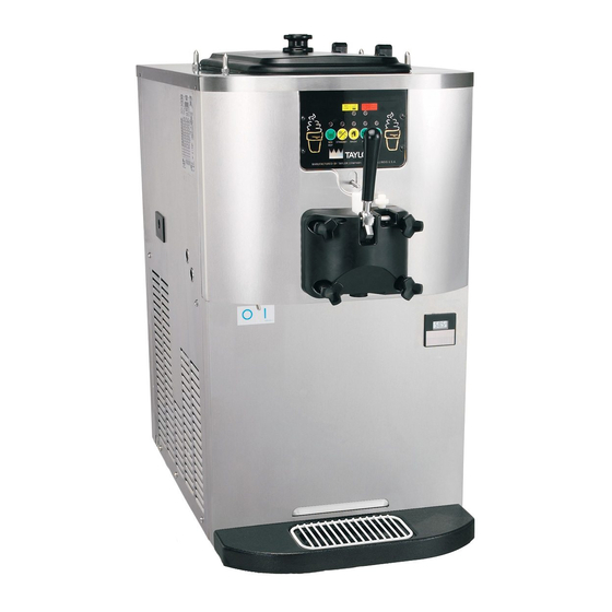
Page 13: Model C707
Operator Parts Identification Section 4 Model C707 Figure 4-1 Item Description Part No. Item Description Part No. Kit A.-Cover-Hopper X65368 Panel A.-Side-Right X64151 Pan-Drip 11-5/8 Long 027503 Panel-Rear 056077-SP1 Pin-Retaining-Hopper CVR 043934 Orifice 022465-100 Panel-Side-Left 066722-SP3 O-ring-3/8 OD X .070 W... -
Page 14: Model C707 Single-Spout Door And Beater Assembly
OPERATOR PARTS IDENTIFICATION Model C707 Single-Spout Door and Beater Assembly Figure 4-2 Item Description Part No. Item Description Part No. Door A. -1SPT 3.4QT X56071-SER O-ring-7/8 OD X .103W 014402 (100 To Bag) Baffle A.-Long 4 IN X50882 Nut-Stud-Long 058765 Handle A.-Draw-Welded... -
Page 15: Brushes
OPERATOR PARTS IDENTIFICATION Brushes Figure 4-3 Item Description Part No. Item Description Part No. Brush−Rear·BRG·1 D X 2 LG 013071 Brush-Mix·Pump·Body-3 X 7 023316 Brush−Double·Ended 013072 Brush-End-Door-Spout 039719 Brush−Draw·Valve·1 X 2 X 17 013073 Operator Parts Identification Model C707... - Page 16 OPERATOR PARTS IDENTIFICATION Notes: Operator Parts Identification Model C707...
- Page 17 Figure 5-1 Item Description Item Description MIX LOW Indicator Light AUTO Key MIX OUT Indicator Light RESET Button - Beater Motor MIX REF Key Power Switch (Toggle) STANDBY Key Hopper Temperature Indicator WASH Key Flavor Burst Jack User Interface Model C707...
-
Page 18: Symbol Definitions
When the MIX REF key is pressed, the light comes on to symbols are used on many of our operator switches, indicate the mix hopper refrigeration system is operating. function, and fault indicators. Your Taylor machine is The MIX REF function cannot be canceled unless the designed with these International symbols. -
Page 19: Wash Key
Taylor service technician. Adjustable Draw Handle Figure 5-3 The Model C707 features an adjustable draw handle to provide the best portion control. The draw handle should WASH Key be adjusted to provide a flow rate of 5 oz. to 7-1/2 oz. -
Page 20: Feed Tube Assembly
The air orifice is used to meter a certain amount overrun. of air into the freezing cylinder. The air orifice maintains overrun and allows enough mix to enter the freezing 12304 cylinder after a draw. Figure 5-6 User Interface Model C707... -
Page 21: Section 6: Operating Procedures
Operating Procedures Section 6 The C707 machine stores mix in a hopper. It has a 3.4 qt. 11269 (3.2 L) freezing cylinder and a 20 qt. (18.9 L) mix hopper. This machine uses a feed tube to allow mix to flow into the freezing cylinder. - Page 22 7. Slide the beater the remainder of the way into the freezing cylinder and over the end of the driveshaft. The beater should fit snugly but still allow slight rotation to engage the driveshaft. 10162 Figure 6-4 Operating Procedures Model C707...
- Page 23 11. Install the draw valve: Slide the two O-rings into the 13. Slide the two O-rings into the grooves on the prime plug. Apply an even coat of Taylor Lube to the grooves on the draw valve and lubricate.
- Page 24 Make sure the hole in the air orifice is clean and is not clogged. If the hole in the air orifice should become clogged, use soap and hot water to clear the hole. Do not enlarge the hole in the air orifice. Figure 6-11 Operating Procedures Model C707...
-
Page 25: Sanitizing
3. While the solution is flowing into the freezing cylinder, take particular care to brush-clean the mix level sensing probe on the front wall and the bottom of the hopper, the mix hopper, and the feed tube. 12178 Figure 6-15 Figure 6-17 Operating Procedures Model C707... - Page 26 7. When a steady stream of sanitizing solution is flowing from the prime plug opening in the bottom of the freezer door, pull the draw handle down. Draw off all of the sanitizing solution. Figure 6-20 Operating Procedures Model C707...
-
Page 27: Priming
9. Lubricate the mix feed tube O-rings on the end of the tube with the small hole on the side. Stand the mix feed tube in the corner of the mix hopper. Figure 6-26 Operating Procedures Model C707... -
Page 28: Closing Procedure
MIX LOW light will shut off. Note: The MIX REF light will come on, indicating the mix refrigeration system is maintaining mix in the mix hopper. 6. Place the mix hopper cover in position. Operating Procedures Model C707... - Page 29 O-ring to be removed, always remove the rear O-ring door spout, raise the draw handle and press the first. This will allow the O-ring to slide over the WASH key to cancel the Wash mode. forward rings without falling into the open grooves. Operating Procedures Model C707...
- Page 30 7. Rinse all parts with clean, warm water. Place the parts on a clean, dry surface to air-dry overnight. 8. Wipe clean all exterior surfaces of the freezer. 6-10 Operating Procedures Model C707...
-
Page 31: Section 7: Operator's Checklist
Too strong of a solution may damage the parts, while too weak of a solution will not do an adequate job of cleaning or sanitizing. The temperature of the mix in the mix hopper and walk-in cooler should be below 40ºF (4.4ºC). Operator’s Checklist Model C707... -
Page 32: Regular Maintenance Checks
This is extremely important. Failure to follow this procedure may cause severe and costly damage to the refrigeration system. Your local Taylor distributor can perform this winter storage service for you. Wrap detachable parts of the freezer, such as beater, blades, driveshaft, and freezer door, and place them in a protected dry place. - Page 33 Missing or worn driveshaft seal on a. Install or replace regularly. into the rear drip pan. driveshaft. b. The rear shell bearing is worn. b. Call service technician to replace rear - - - shell bearing. Troubleshooting Guide Model C707...
- Page 34 Inadequate level of mix in the mix a. Fill the mix hopper with mix. into the freezing hopper. cylinder. a. The mix inlet hole is frozen up. a. The mix hopper temperature needs - - - adjustment. Call service technician. Troubleshooting Guide Model C707...
- Page 35 White Bristle Brush, 1/2” x 1/2” Inspect & Replace if Minimum Necessary White Bristle Brush, 3/16” x 1” Inspect & Replace if Minimum Necessary White Bristle Brush, 3” x 1/2” Inspect & Replace if Minimum Necessary Parts Replacement Schedule Model C707...
- Page 36 PARTS REPLACEMENT SCHEDULE Notes: Parts Replacement Schedule Model C707...
- Page 37 Limited Warranty Taylor warrants the Product against failure due to defect in materials or workmanship under normal use and service as follows. All warranty periods begin on the date of original Product installation. If a part fails due to defect during the applicable warranty period, Taylor, through an authorized Taylor distributor or service agency, will provide a new or ...
- Page 38 7. Failure, damage, or repairs due to faulty installation, misapplication, abuse, no or improper servicing, unauthorized alteration, or improper operation or use as indicated in the Taylor Operator’s Manual, including but not limited to the failure to use proper assembly and cleaning techniques, tools, or approved cleaning supplies.
- Page 39 Legal Remedies The owner must notify Taylor in writing, by certified or registered letter to the following address, of any defect or complaint with the Product, stating the defect or complaint and a specific request for repair, replacement, or other correction of the Product under warranty, mailed at least thirty (30) days before pursuing any legal rights or remedies.
- Page 40 LIMITED WARRANTY ON MACHINES Notes: 10-4 Limited Warranty on Machines Model C707...
- Page 41 Taylor warrants the Parts against failure due to defect in materials or workmanship under normal use and service as follows. All warranty periods begin on the date of original installation of the Part in the Taylor machine. If a Part fails due to defect during the applicable warranty period, Taylor, through an authorized Taylor distributor or service agency, will provide a new or re-manufactured Part, at Taylor’s option, to replace the failed defective Part at no charge for the Part.
- Page 42 Parts or the machines in which they are installed repaired or altered in any way so as, in the judgment of Taylor, to adversely affect performance, or normal wear or deterioration.
- Page 43 Legal Remedies The owner must notify Taylor in writing, by certified or registered letter to the following address, of any defect or complaint with the Part, stating the defect or complaint and a specific request for repair, replacement, or other correction of the Part under warranty, mailed at least thirty (30) days before pursuing any legal rights or remedies.
- Page 44 LIMITED WARRANTY ON PARTS Notes: 11-4 Limited Warranty on Parts Models C707...
Need help?
Do you have a question about the C707 and is the answer not in the manual?
Questions and answers