Taylor McDonald's C602 Manual
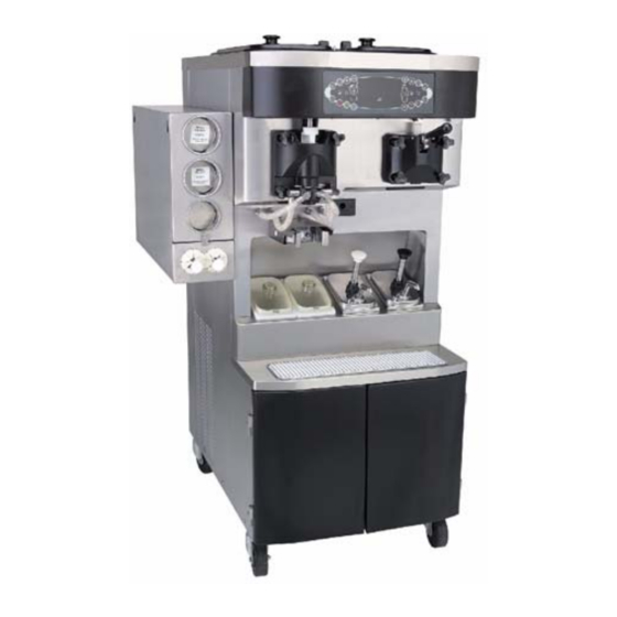
Soft serve/shake combination freezer
Hide thumbs
Also See for McDonald's C602:
- Original service instructions (178 pages) ,
- Service manual (114 pages) ,
- Pocket manual (92 pages)
Table of Contents
Advertisement
Soft Serve/Shake Combination Freezer
Taylor Model C602
Place this chapter in the Shakes/Desserts
section of the Equipment Manual.
Manufactured exclusively for
McDonald's® by
Taylor® Company
750 N. Blackhawk Blvd.
Rockton, IL 61072
Phone: (815) 624-8333
Toll Free Number
Outside Illinois:
1 (800) 228-8309
Inside Illinois:
1 (800) 851-5639
Fax: (815) 624-8000
Table of Contents
. . . . . . . . . . . . . . . . . . . . . . . . . . . . . . . . . . . . . . . . . . . . . . . . . . . . . . . . . .
Warranty
A warranty checkout card is shipped with every new freezer that leaves the factory. The warranty checkout card is
packed in an envelope which also contains this operator's manual. Refer to the warranty checkout card and the warranty
classifications listed in the Parts Identification/Function section when service is performed on your freezer.
It is recommended that the operator take the necessary time to carefully read through the complete warranty information
contained in the warranty checkout card. Any questions or unclear statements found within the card should be made
clear to you upon delivery of the freezer. Thoroughly understand your warranty protection before you begin operation.
For any questions pertaining to the Taylor Company Warranty, please contact your authorized Taylor Distributor or
Taylor Company, Rockton, Illinois 61072.
This manual is for the exclusive use of licensees and employees of McDonald's Corporation.
E2005 McDonald's Corporation
All Rights Reserved
Downloaded from
www.dlmanuals.com
. . . . . . . . . . . . . . . . . . . . . . . . . . . . . . . . . . . . . . . . . . . . . . . . . . . . .
. . . . . . . . . . . . . . . . . . . . . . . . . . . . . . . . . . . . . . .
. . . . . . . . . . . . . . . . . . . . . . . . . . . . . . . . . . . . . . . . .
. . . . . . . . . . . . . . . . . . . . . . . . . . . . . . . . . . . . . . . . .
. . . . . . . . . . . . . . . . . . . . . . . . . . . . . . . . . . . . . . . . . . . . . . . . . . . .
. . . . . . . . . . . . . . . . . . . . . . . . . . . . . . . . . . . . . . . . .
. . . . . . . . . . . . . . . . . . . . . . . . . . . . . . . . . . . . . . . . . . . . .
. . . . . . . . . . . . . . . . . . . . . . . . . . . . . . . . . . . . . . . . . . .
. . . . . . . . . . . . . . . . . . . . . . . . . . . . . . . . . . . . . . . . . . . . . . . .
. . . . . . . . . . . . . . . . . . . . . . . . . . . . . . . . . . . . . . . . . . . . . . . . . . . .
. . . . . . . . . . . . . . . . . . . . . . . . . . . . . . . . . . . . . . . . . . . . . . . . .
. . . . . . . . . . . . . . . . . . . . . . . . . . . . . . . . . . . . . . . . . . . .
. . . . . . . . . . . . . . . . . . . . . . . . . . . . . . . . . . . . . .
. . . . . . . . . . . . . . . . . . . . . . . . . . . . . . . . . . . . . .
. . . . . . . . . . . . . . . . . . . . . . . . . . . . . . . . . . . . . . . . . . . . . . . . .
. . . . . . . . . . . . . . . . . . . . . . . . . . . .
Printed in May
EM SD11
Page
1
Page
1
Page
4
Page 31
Page 34
Page 39
Page 42
Page 47
Page 50
Page 54
Page 60
Page 74
Page 78
Page 88
Page 98
Page 99
Page 100
Printed in
The United States of America
Advertisement
Table of Contents

Related Manuals for Taylor McDonald's C602


Summary of Contents for Taylor McDonald's C602
-
Page 1: Table Of Contents
Any questions or unclear statements found within the card should be made clear to you upon delivery of the freezer. Thoroughly understand your warranty protection before you begin operation. For any questions pertaining to the Taylor Company Warranty, please contact your authorized Taylor Distributor or Taylor Company, Rockton, Illinois 61072. -
Page 2: Introduction
WASH and OFF modes by selecting any of All repairs must be performed by an the four flavor symbols to enable cleaning, authorized Taylor service agent. The main sanitizing, and priming. power supplies to the freezer must be disconnected prior to performing any repairs. - Page 3 This freezer is designed to operate indoors, under normal ambient temperatures of DO NOT operate the freezer unless all 70° - 75°F (21° - 24°C). The freezer has service panels and access doors are successfully performed in high ambient restrained with screws. Failure to follow this temperatures of 104°F (40°C) at reduced instruction may result in severe personal injury capacities.
- Page 4 Notes: Downloaded from www.dlmanuals.com...
-
Page 5: Parts Identification/Function
PARTS IDENTIFICATION/FUNCTIONS Exploded View (See Figure 1) ITEM PART NO. DESCRIPTION QTY. FUNCTION WARR. CLASS 053809-1 Cover-Hopper*Black* Protects mix in mix hopper from any debris. Helps keep temperature in mix hopper uniform. X44797 Agitator Assembly Stirs product in mix hopper to assure even temperature. - Page 6 Exploded View (Continued) ITEM PART NO. DESCRIPTION QTY. FUNCTION WARR. CLASS 056131 Plate-Dec. Touch sensor display panel on front of machine. 055957 Panel-Side Left Panel which provides access to internal components. 052779-3 Filter-Air 18.0 L x Filters dust and dirt from the main 13.5 H x .70 W condenser.
- Page 7 Front View (See Figure 2) ITEM PART NO. DESCRIPTION QTY. FUNCTION WARR. CLASS X35584SER2 Motor A.-Spinner Turns spinner shaft assembly. 059462 Solenoid -Draw Valve Energized to raise the shake draw valve. 020108 Coupling-Flexible Connects spinner motor to W/Screws coupling assembly and provides adjustment for spinner shaft.
- Page 8 Front View (Continued) ITEM PART NO. DESCRIPTION QTY. FUNCTION WARR. CLASS X53800-BRN Pump A.-Syrup- Dispenses heated sundae Heated (Chocolate) topping. X53800-TAN Pump A.-Syrup- Dispenses heated sundae Heated (Caramel) topping. 056008 Holder-Cup Shake Holds cup in place during dispensing. 051574 Screw-Adjustment Adjusts the sensing eye to determine correct level of shake.
- Page 9 Front View Figure 2 Downloaded from www.dlmanuals.com...
- Page 10 Syrup Cabinet View (See Figure 3) ITEM PART NO. DESCRIPTION QTY. FUNCTION WARR. CLASS 056016 Shelf-Syrup Provides access to syrup pumps. 052916 Pump-Peristaltic Pumps syrup to freezer door. 058725 Motor-Gear 161 RPM Drives peristaltic pump rollers. 059144 Rack-Syrup Cabinet Rack for storage. Door 058613 Block-Hinge...
- Page 11 Mix Pump & Tubes (See Figure 4) ITEM PART NO. DESCRIPTION QTY. FUNCTION WARR. CLASS 052916 Pump-Peristaltic Contains rollers to propel syrup. X54978 Kit A.-Peristaltic Pump Compressed by pump rollers to Tube propel syrup. 053036 Ferrule-.625 ID Clamps syrup hose on fitting. 054526 Fitting-Peristaltic Connects line to pump tube.
- Page 12 Mix Hopper - Top View (See Figure 5) ITEM PART NO. DESCRIPTION QTY. FUNCTION WARR. CLASS X44761 Sleeve A.-Mix Pump Hub used to hold the air/mix pump in a locked position. X41348 Probe A.-Mix Out Electrical device to indicate level of mix in the hopper.
- Page 13 X57028-XX Pump A. - Mix Simplified - Shake (See Figure 6) ITEM PART NO. DESCRIPTION QTY. FUNCTION WARR. CLASS 1 - 7 X57028-XX Pump A.-Mix Delivers air and mix to the Simplified Shake freezing cylinder. 057944 Cylinder-Pump- Chamber to house the piston. Hopper-Shake X55450 Pin A.-Retaining...
- Page 14 X57028-XX Pump A. - Mix Simplified - Shake Figure 6 Downloaded from www.dlmanuals.com...
- Page 15 X57029-XX Pump A. - Mix Simplified - Soft Serve (See Figure 7) ITEM PART NO. DESCRIPTION QTY. FUNCTION WARR. CLASS 1 - 7 X57029-XX Pump A.-Mix Delivers air and mix to freezing Simplified Soft Serve cylinder. 057943 Cylinder-Pump- Chamber to house the piston. Hopper-Soft Serve X55450 Pin A.-Retaining...
- Page 16 X57029-XX Pump A. - Mix Simplified - Soft Serve Figure 7 Downloaded from www.dlmanuals.com...
- Page 17 X56652 Syrup Line Assembly - Triple Thick Shake Syrup (See Figure 8) ITEM PART NO. DESCRIPTION QTY. FUNCTION WARR. CLASS 053036 Ferrule-.625 ID Clamps syrup hose on fitting. 056675 Fitting-Barb Connects syrup lines to front panel. 500205 O-Ring Provides seal for quick disconnect fitting.
- Page 18 X59304 Syrup Line Assembly - Thin Viscosity Syrup (See Figure 9) ITEM PART NO. DESCRIPTION QTY. FUNCTION WARR. CLASS 029834 Ferrule-.650 ID Clamps syrup hose on fitting. 056675 Fitting-Barb Connects syrup lines to front panel. 500205 O-Ring Provides seal for quick disconnect fitting.
- Page 19 X58450 Syrup Line Assembly - Syrup-In-Bag Option (See Figure 10) ITEM PART NO. DESCRIPTION QTY. FUNCTION WARR. CLASS 024278 O-Ring-1/2 OD x .070 Provides a seal in the pump tube connection. 054526 Fitting-Male Connects to the pump tube. 053036 Ferrule-.625 ID NP Secures the fitting on the hose.
- Page 20 X59143 Tray A.-Syrup Tray used when syrup is dispensed from a bag. (Optional bag syrup system) 048232 Lubricant-Taylor Lubricant for moving parts and Hi-Performance wear items. 059088 Tray-Parts Shake Side Plastic tray used for air drying parts when cleaning the machine.
- Page 21 Accessories ITEM PART NO. DESCRIPTION QTY. FUNCTION WARR. CLASS X49463-59 Kit A.-Tune Up C602 Tune up kit containing: 1/X56200-10 pump kit, 1/X56200-12 draw valve kit, 1/X56200-13 shake door kit, 1/X56200-14 soft serve door kit, 1/X56200-15 syrup valve kit, 1/048260 o-ring removal tool. 047912 Deflector-Blower Attached under the base of the...
- Page 22 X44127 Brush Kit Assembly (See Figure 12) ITEM PART NO. DESCRIPTION QTY. FUNCTION WARR. CLASS 013071 Black Bristle Brush Used to clean rear shell bearing and mix pump drive hub. 013072 Double End Brush Used to clean o-rings, holes in metal parts, piston grooves, mix inlet tube, mix inlet adapter, o-ring all grooves, draw valve core, valve...
- Page 23 Beater Door Assembly - Shake Side (See Figure 13) ITEM PART NO. DESCRIPTION QTY. FUNCTION WARR. CLASS 032560 Seal-Drive Shaft Provides seal from product inside freezing cylinder to internal areas of freezer. 050985 Shaft-Beater 7 Qt. Connects beater assembly to gear Fluted Blade unit.
- Page 24 Beater Door Assembly - Shake Side Figure 13 Downloaded from www.dlmanuals.com...
- Page 25 Beater Door Assembly - Soft Serve Side (See Figure 14) ITEM PART NO. DESCRIPTION QTY. FUNCTION WARR. CLASS X56421-1 Handle A.-Draw Operational component of the draw valve assembly. 055989 Nut-Stud Tightening mechanism to secure freezer door to freezing cylinder. X57332-SER Door A.-w/Baffle Covers open end of freezing cylinder and provides port for the...
- Page 26 Beater Door Assembly - Soft Serve Side Figure 14 Downloaded from www.dlmanuals.com...
- Page 27 X53800-BRN/TAN Syrup Pump (See Figure 15) ITEM PART NO. DESCRIPTION QTY. FUNCTION WARR. CLASS X36576-TAN Plunger A. Used to dispense toppings. X36576-BRN 032762-TAN Knob-Plunger Holds plunger assembly in place. 032762-BRN TAN and BRN indicate the hot caramel and hot fudge toppings. 016369 O-Ring-Knob Seals top of inlet cavity and...
- Page 28 X53800-BRN/TAN Syrup Pump Figure 15 Downloaded from www.dlmanuals.com...
- Page 29 059088 Tray-Parts-Shake Side Figure 16 ITEM PART NO. DESCRIPTION ITEM PART NO. DESCRIPTION X50958 Beater A.-7 Qt. X57169 Valve A.-Draw 041103 Blade-Scraper-16” 500598 Valve-Check Duckbill 050985 Shaft-Beater 7 Qt. 055605 Bearing-Door Front 032560 Seal-Drive Shaft 020571 O-Ring - 1-1/16 OD 055989 Nut-Stud (Draw Valve)
- Page 30 059087 Tray-Parts-Soft Serve Side Figure 17 ITEM PART NO. DESCRIPTION ITEM PART NO. DESCRIPTION X56421-1 Handle A.-Draw 050347 Shoe-Front Helix- Front 055819 Pin-Pivot 032564 Drive Shaft 050348 Bearing-Front 032560 Seal-Drive Shaft 055989 Nut-Stud 046235 Blade-Scraper 014402 O-Ring (Draw Valve) 046236 Clip-Scraper Blade 048926 Gasket (Freezer...
- Page 31 056525 Tray-Parts-Pump-Simplified Figure 18 Shake Side Soft Serve Side ITEM PART NO. DESCRIPTION ITEM PART NO. DESCRIPTION 044641 Clip-Mix Pump 044641 Clip-Mix Pump Retainer Retainer 057944 Cylinder-Pump- 057943 Cylinder-Pump- Hopper-Shake Hopper-Soft Serve X55450 Pin A.-Retaining X55450 Pin A.-Retaining 053526 Piston 053526 Piston 044731...
-
Page 32: Important To The Operator
IMPORTANT TO THE OPERATOR Figure 19 ITEM DESCRIPTION FUNCTION Keypad-Shake Used for selecting operating functions on the shake side of the machine. Display-Vacuum Screen which displays menu options and notifies operator if a Fluorescent Menu (VFD) fault is detected. Keypad-Menu Used to select the Manager’s Menu or to exit the Menu Display. - Page 33 To better communicate in the International arena, the words on many of our operator keys have been replaced by symbols to indicate their functions. Your Taylor equipment = MENU DISPLAY is designed with these International symbols. The following chart identifies the symbol definitions.
- Page 34 Heat Mode Symbol WARNING: Do not use metal objects When the HEAT MODE symbol to press the reset button. Failure to comply illuminated, the freezer is in the process of a may result in severe personal injury or death. heat cycle. The heat mode symbol may be If the beater motor is turning properly, touch selected to start a heat cycle following a freezer soft lock condition.
-
Page 35: Daily Opening Procedures
Shake Fill Level Adjustment DAILY OPENING PROCEDURES The portion control sensor located under the Before performing the opening procedures, cup holder can be adjusted to fill the cup to check the display panel for any error the desired level. If the fill level is too low, or messages. - Page 36 4. Fill the topping containers with topping. 3. Return to the freezer with a small amount Place the caramel and fudge topping of sanitizing solution. With a pail below containers in the heated wells. Place the the door spout, dip the door spout brush remaining two topping containers in the into the sanitizing solution.
- Page 37 5. Fill the squeeze bottle with sanitizing 8. With the pail still beneath the door, solution. With a pail beneath the door, remove the syrup nose fitting from the insert the tube end of the squeeze bottle syrup line fitting by turning it into the syrup port, and squeeze the bottle counter-clockwise.
- Page 38 14. Install the duckbill valve into the syrup If the tip is not flat, remove the syrup nose nose fitting with the flat end aligned with fitting and remove/reinstall the duckbill the open slot in the syrup nose fitting. valve. Using a shake cup filled with McD Sanitizer (HCS), rinse the syrup nose Note: Replace the duckbill valve if it is fitting to wet the bottom of the duckbill...
- Page 39 25. Repeat steps 23 - 24 to prime the rest of 21. Touch the AUTO symbol or the the syrup lines. After priming is complete, OPTIONAL FLAVOR symbol to scroll exit the SYRUP PRIME mode by touching the arrow to SYRUP PRIME. the CALIBRATION symbol (See Figure 33.) 26.
-
Page 40: Syrup System
30. When ready to resume normal operation, Note: To assure sanitary conditions are maintained, brush clean each item for a total touch the AUTO symbol . (See of 60 seconds, repeatedly dipping the brush in Figure 37.) The control has a feature in sanitizing solution. - Page 41 Once this rate is set, the correct amount of 2. Touch the AUTO symbol or the syrup will be blended with the shake base OPTIONAL FLAVOR symbol to scroll regardless of the size of shake served. Please the arrow to SYRUP CALIBRATION. (See note that syrup calibration is critical when Figure 42.) changing the promotional 4th flavor syrup.
- Page 42 5. To calibrate the syrup dispensing rate, Syrup Priming Procedure hold the small portion of the calibration The purpose of priming the syrup line is to cup under the valve for the flavor to be eliminate any air in the syrup delivery system. calibrated.
-
Page 43: Daily Closing Procedures
DAILY CLOSING PROCEDURES 8. Touch the AUTO symbol or the OPTIONAL FLAVOR symbol to scroll This procedure must be done at the close of the arrow to SYRUP PRIME. (See business. Figure 47.) UNFLAVORED DRAW Shake Side SYRUP CALIBRATION Important: The level of mix in the mix hopper >... - Page 44 5. Place the restrictor cap, front drip tray, 10. Return to the freezer with a small amount shake cup holder and splash shield on a of cleaning solution. With a pail below the clean, dry surface to air-dry overnight or door spout, dip the door spout brush into until the heating cycle is complete.
- Page 45 13. Fill the squeeze bottle with cleaning 15. Raise each retainer pin. Install the syrup solution. With a pail beneath the door, hole plugs in the syrup ports in the freezer insert the tube end of the squeeze bottle door. Lower the retainer pins to secure into the syrup ports, and squeeze the the hole plugs in the door.
- Page 46 Soft Serve Side 5. Rinse these parts in cool, clean water. This procedure must be done at the close of business. 6. Draw a small amount of McD All Purpose Super Concentrate (APSC) (HCS) Important: The level of mix in the mix hopper cleaning solution from the sink must be above the mix low probe.
- Page 47 10. Remove, clean and reinstall the long drip 13. Using a clean, sanitized towel, wipe down pan through the front panel. the freezer door, front panel, the area (See Figure 60.) around the bottom of the freezer door, and any other areas that demonstrate a build-up of either moisture or food substance.
-
Page 48: Scheduled Maintenance - Syrup System
SCHEDULED MAINTENANCE - the FLAVOR SELECT symbol to stop SYRUP SYSTEM the pump. 10. Repeat steps 3 through 9 using Sanitizer (HCS). One packet in 2-1/2 Syrup Pump Tube Removal gal. (9-1/2 liters) of water = 100 PPM. 1. Remove the syrup feed tubes from the 11. - Page 49 1. Lubricate the o-rings on the syrup line pail of McD All Purpose Super fittings with Taylor Lube HP. Concentrate (APSC) (HCS). 3. Raise the retainer and remove the syrup valve from the freezer door. Place the valve in a pail located under the draw valve.
- Page 50 15. Install the duckbill valve into the syrup the syrup line fitting. If the tip will not nose fitting, with the flat end aligned with remain flat when the syrup fitting is the open slot in the syrup nose fitting. assembled, replace the duckbill valve.
-
Page 51: Syrup Topping Pump
5. Remove the plunger tube and the insert SYRUP TOPPING PUMP from the plunger assembly. (See Figure 69.) Syrup Topping Pump Disassembly Before the first use, and after use weekly, disassemble and clean the pump. 1. Flush and rinse the pump in a container of warm water. - Page 52 8. Remove the seal o-ring from the seal. 12. Remove the discharge tube from the (See Figure 72.) valve body. (See Figure 75.) Figure 72 Figure 75 9. Remove the discharge tube lock nut by turning it counterclockwise. Remove the 13.
- Page 53 4. Insert the black shielded brush into the 7. Move the brush back and forth to scrub top side of the inlet valve. Scrub this area, this passageway. Advance the brush specifically around the steel ball. completely, and pull the brush out of the (See Figure 77.) valve body.
- Page 54 Syrup Topping Pump Assembly 7. Install the plunger tube assembly onto the plunger assembly by inserting the plunger After pump disassembly and cleaning is assembly into the larger opening on the complete, assemble the pump. plunger tube. Push the plunger assembly, 1.
-
Page 55: Manual Brush Cleaning
10. Lubricate and install the 1-5/16” o-ring into 15. Lubricate and install the plunger assembly the valve body. (See Figure 86.) into the cylinder opening in the pump body. (See Figure 87.) Figure 87 16. Tighten the plunger nut by turning it Figure 86 clockwise. - Page 56 Draining Product From The Freezing 6. Drain the product from the freezing Cylinder cylinder and the mix hopper. (See Figure 90.) To drain the product from the freezing cylinders on both sides of the machine, the steps will be the same. Therefore, first drain the product from the shake side, then go back and duplicate these procedures for the soft serve side.
- Page 57 Rinsing 3. Open the draw valve on the freezer door. Drain all the rinse water from the door spout, close the draw valve, and touch the 1. Pour two gallons (7.6 liters) of cool, clean water into the shake mix hopper. With the WASH symbol, cancelling the wash mode.
- Page 58 8. Prepare 2.5 gallons (9.5 liters) of McD 6. Remove the freezer door o-ring, front Sanitizer (HCS) solution. Use one packet bearing, retainer pins, and the draw valve in 2.5 gallons (9.5 liters) of water (100 spinner assembly. PPM). Repeat steps 2 through 7 with the sanitizing 7.
- Page 59 10. Remove the pump drive shaft from the 7. Remove the pump drive shaft from the drive hub in the rear wall of the mix drive hub in the rear wall of the mix hopper. (See Figure 95.) hopper. (See Figure 96.) Figure 95 Remove the two small o-rings and one large o-ring from the pump drive shaft.
- Page 60 10. Remove the two short drip pans from the 4. Return to the freezer with a small amount rear panel. Remove the two notched drip of cleaning solution. Using the black pans from the left and right side panels. brush, clean the rear shell bearings at the Take them to the sink for cleaning.
-
Page 61: Equipment Set-Up
Figure 101 signs of wear. If any nicks are present, replace the blades. Note: When lubricating parts, use an approved food grade lubricant (example: Note: Shake side scraper blades should be Taylor Lube HP). replaced every 6 months. Downloaded from www.dlmanuals.com... - Page 62 If the blades are in good condition, place 5. Assemble the draw valve spinner each scraper blade over the holding pins assembly. Inspect draw valve o-rings for on the beater assembly. (See Figure 104.) cuts or nicks. (Replace if cut or nicked.) If draw valve o-rings are in good condition, slide the 2 o-rings into the grooves of the draw valve and lubricate.
- Page 63 7. Insert the spinner shaft seal into the 9. Squeezing the split end together, insert bottom of the draw valve as far as it will the driven spinner through the metal go. The spinner shaft seal should fit into opening of the draw valve until it snaps the seal groove located inside the draw into place.
- Page 64 11. Place the freezer door o-ring into the 13. Lubricate the shaft of the spinner blade up groove on the back of the freezer door. to the groove. (See Figure 114.) Lubricate the outside diameter of the front bearing. Slide the front bearing into the door hub.
- Page 65 16. Snap the restrictor cap over the end of the (See Figure 118.) door spout and install the syrup valve retainer pins. (See Figure 117.) Figure 118 Note: When lubricating parts, use an approved food grade lubricant (example: Taylor Lube HP). Figure 117 Downloaded from www.dlmanuals.com...
- Page 66 Note: To ensure the mix does not leak out of 3. Before installing the beater assembly, the back of the freezing cylinder, the middle check the scraper blades for any nicks or section of the boot seal should be convex or signs of wear.
- Page 67 5. Install the beater shoes. (See Figure 123.) 8. Lightly lubricate inside of the top of the freezer door valve cavity. (See Figure 126.) Figure 123 6. Slide the beater assembly the rest of the Figure 126 way into the freezing cylinder. Insert the draw valve from the top, with Make sure the beater assembly is in the draw handle slot facing forward.
- Page 68 10. Install the freezer door. Insert the baffle 12. Slide the long drip pan into the hole in the rod through the beater in the freezing front panel above the syrup topping cylinder. With the door seated on the dispensers. (See Figure 131.) freezer studs, install the handscrews.
- Page 69 Mix Pump Assembly 4. Insert the piston into the retaining pin hole end of the pump cylinder. (See Figure 136.) 1. Inspect the rubber pump parts. O-rings and gasket must be in 100% good 15118 condition for the pump and entire machine to operate properly.
- Page 70 7. Insert the valve cap into the hole in the Note: The head of the retaining pin mix inlet adapter. (See Figure 139.) should be located at the top of the pump when installed. 15111 10. Assemble the feed tube assembly. Slide the check ring into the groove of the feed tube.
- Page 71 13. Slide the large black o-ring and the two Sanitizing - Shake Side smaller black o-rings into the grooves on 1. Prepare 2.5 gallons (9.5 liters) of McD the drive shaft. Thoroughly lubricate the Sanitizer (HCS) solution. Use one packet o-rings and shaft.
- Page 72 13. Touch the PUMP symbol to sanitize the inside of the air/mix pump and the mix CAUTION! feed tube. Install the pump end of the mix feed tube and secure with the cotter pin. 14. Open the draw valve and draw off all the Failure to follow this instruction could remaining sanitizing solution.
- Page 73 17. Remove the cotter pin from the pump. Sanitizing - Soft Serve Side Stand the mix feed tube in the corner of 1. Prepare 2.5 gallons (9.5 liters) of McD the mix hopper. Place the cotter pin in Sanitizer (HCS) solution. Use one packet position in the outlet fitting of the pump.
- Page 74 5. Prepare another 2.5 gallons (9.5 liters) of 11. Place the agitator on the agitator drive McD Sanitizer (HCS) solution. Use one shaft housing. (See Figure 155.) packet in 2.5 gallons (9.5 liters) of water (100 PPM). 6. Pour the sanitizing solution into the mix hopper.
-
Page 75: Vfd Screens
Priming - Shake Side 5. Fill the hopper with fresh mix and place the mix hopper cover in position. Note: Use only FRESH MIX when priming the freezer. Priming - Soft Serve Side 1. With a mix pail beneath the door spout, touch any FLAVOR SELECT symbol Note: Use only FRESH MIX when priming the open the draw valve. - Page 76 During the INITIALIZING... LANGUAGE Power Switch ON screen, the alarm will be on. If the system de- When the power switch is placed in the ON tects corrupt data during INITIALIZING, the position, the control panel touch keys become following display will alert the operator that the operative.
- Page 77 Hard Lock: There are two causes of a hard lock failure: DO NOT attempt to draw product or disassemble the unit during the HEAT cycle. 1. The brush clean timer has elapsed The product is hot and under extreme (maximum setting of 14 days). pressure.
- Page 78 If the machine has hard locked and an attempt Following are the variable messages for soft is made to enter AUTO, the machine will enter lock failures that appear on the second line of the STANDBY mode and display the following the screen.
-
Page 79: Manager's Menu
When one of these messages appears, Note: A record of Heat Cycle Data and Lock Out History can be found in the Manager’s automatic freezer operation cannot take place Menu. (See page 85.) until the freezer is disassembled and brush cleaned, or has completed a heat treatment cycle. - Page 80 The sundae side will continue operation in the Menu Options mode it was in when the Menu was selected. Touch the AUTO symbol or OPTIONAL However, the sundae side control keys will not FLAVOR symbol to move up or down be lit and are non-functional when the through the Menu.
- Page 81 The VERIFY CALIBRATION option is used to Reset the SERVING COUNTER by selecting verify the amount of syrup dispensed is within the CALIBRATION symbol to advance to the proper specification. (See Figure 180.) the next screen. Select the AUTO symbol to move the arrow (>) to YES and select the VERIFY CALIBRATION CALIBRATION symbol...
- Page 82 Note: Do not advance the Auto Heat Time Change the time by touching the AUTO setting except on the day the unit is brush OPTIONAL FLAVOR symbol with the cleaned. Increasing the time between heat cursor under the hour position. Move the cycles will cause the machine to soft lock if the cursor to the minutes by selecting the start of the cycle does not begin within 24...
- Page 83 Enable the AUTO START TIME by selecting Repeat the steps to activate Standby on the remaining side. (See Figure 192.) the AUTO symbol to move the arrow up to Enable. Select the CALIBRATION symbol to advance to the next screen. STANDBY MODE (See Figure 190.) LEFT...
- Page 84 The MIX LEVEL AUDIBLE option when HPCO COMPRESSOR - Place the power enabled will alert the operator with an audible switch in the OFF position. Wait 5 minutes for tone when there is mix low or mix out the machine to cool. Place the power switch in condition.
- Page 85 Faults Occurring Entering a Heat Treatment Faults Occurring While in AUTO Mode Cycle (L/R) HPR>41F (5C) AFTER 4 HR - The mix POWER SWITCH OFF - The power switch is temperature in the left or right hopper was OFF. above 41 F (5 C) more than four hours.
- Page 86 The HEAT CYCLE DATA screen contains a The remaining lines indicate the following: record of up to 366 heat treatment cycles. The HEAT = Total time for the hopper (h) and most recent heat cycle data will be shown first. barrel (b) to reach 150.9°F (66.1°C).
- Page 87 Listed below are variable failure code The SYSTEM INFORMATION is displayed on messages which could appear on line 2. three separate screens. The first screen contains the control and software version HT HEAT TIME FAILURE installed in the machine. (See Figure 202.) Mix temperature did not rise above F (66.1 C) in less than 90 minutes.
- Page 88 The CURRENT CONDITIONS screen provides Dispensing Shake Without Syrup the viscosity readings for the product when the Beginning with software version 1.04, shakes side is running and hopper and barrel can be dispensed without flavoring by temperatures for both sides of the machine. selecting the left side pump symbol The left column displays the readings for the shake side and the right column displays the...
-
Page 89: Troubleshooting Guide
Downloaded from www.dlmanuals.com... - Page 90 Downloaded from www.dlmanuals.com...
- Page 91 Downloaded from www.dlmanuals.com...
- Page 92 Downloaded from www.dlmanuals.com...
- Page 93 Downloaded from www.dlmanuals.com...
- Page 94 Downloaded from www.dlmanuals.com...
- Page 95 Downloaded from www.dlmanuals.com...
- Page 96 Downloaded from www.dlmanuals.com...
- Page 97 Downloaded from www.dlmanuals.com...
- Page 98 Downloaded from www.dlmanuals.com...
-
Page 99: Parts Replacement Schedule
PARTS REPLACEMENT SCHEDULE PART EVERY EVERY ANNUALLY DESCRIPTION 3 MONTHS 6 MONTHS Scraper Blade-Shake Scraper Blade-Soft Serve Drive Shaft Seal Freezer Door O-Ring-Shake Freezer Door Gasket-Soft Serve Front Bearing Front Beater Shoes-Soft Serve Draw Valve O-Ring Spinner Shaft Seal-Shake Restrictor Cap-Shake Mix Feed Tube O-Ring Pump O-Ring Pump Valve Gasket... -
Page 100: Ordering/Service Information
Taylor Distributor or the It should also be noted, that Taylor does not Taylor Factory. Be prepared to provide the warrant the refrigerant used in its equipment. Model/Serial Number of the unit in question. -
Page 101: Wiring Diagrams
WIRING DIAGRAM 3 PH. 059480-33 Rev. 4/05 Downloaded from www.dlmanuals.com... - Page 102 WIRING DIAGRAM 3 PH. 059480-58 Rev. 4/05 Downloaded from www.dlmanuals.com...
Need help?
Do you have a question about the McDonald's C602 and is the answer not in the manual?
Questions and answers