
Related Manuals for Taylor 793


Summary of Contents for Taylor 793
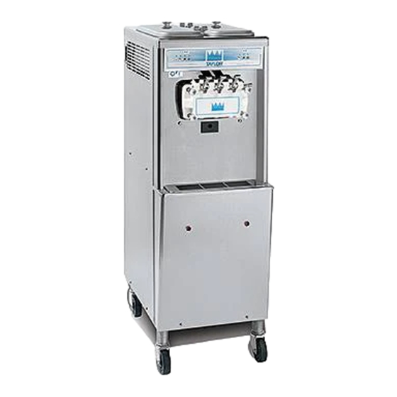
- Page 1 OPERATOR'S MANUAL Model 793 Chick-fil-A Soft Serve Freezer Original Operating Instructions 082304CFAM 6/25/13 (Original Publication) Updated 12/6/13...
- Page 2 Complete this page for quick reference when service is required: Taylor Distributor: Address: Phone: Service: Parts: Date of Installation: Information found on the data label: Model Number: Serial Number: Electrical Specs: Voltage Cycle Phase Maximum Fuse Size: Minimum Wire Ampacity: E 2013 Carrier Commercial Refrigeration, Inc.
-
Page 3: Table Of Contents
....... Model 793 ............ - Page 4 Statutory Damages of up to $250,000 (17 USC 504) for infringement, and may result in further civil and criminal penalties. All rights reserved. Taylor Company a division of Carrier Commercial Refrigeration, Inc. 750 N. Blackhawk Blvd. Rockton, IL 61072 Model 793 Table of Contents...
-
Page 5: To The Installer
Failure service of Taylor® equipment. to follow this instruction may result in electrocution. Only authorized Taylor service personnel should perform installation, maintenance, and repairs on Taylor equipment. This unit must be installed on a level surface Authorized service personnel should consult to avoid the hazard of tipping. - Page 6 If the supply cord is damaged, it must be Refer to the wiring diagram provided inside of the replaced by an authorized Taylor service electrical box for proper power connections. technician in order to avoid a hazard.
- Page 7 It is recommended that beater rotation be performed by an authorized Taylor service technician. Taylor reminds technicians to be aware of and in compliance with local government laws regarding refrigerant recovery, recycling, and Refrigerant reclaiming systems.
-
Page 8: To The Operator
Distributor. unit's refrigeration system, only the refrigerant specified on the affixed data label should be Note: Your Taylor warranty is valid only if the parts used. The unauthorized use of alternate refrigerants are authorized Taylor parts, purchased from the will void your Taylor compressor warranty. It is the... - Page 9 Should a new refrigerant alternate prove, refrigerant as it relates to your compressor warranty, through Taylor's testing, that it would be accepted as call Taylor or your local authorized Taylor distributor. a drop-in replacement for this unit, then the Be prepared to provide the Model/Serial Number of disclaimer in this “Compressor Warranty Disclaimer”...
-
Page 10: Safety
We, at Taylor Company, are concerned about the safety of the operator at all times when they are coming in contact with the unit and its parts. Taylor makes every effort to design and manufacture All repairs should be performed by an built-in safety features to protect both operators and authorized Taylor service technician. - Page 11 78 dB(A) when measured at a distance of safely move this unit. Failure to comply may result in 1.0 meter from the surface of the unit and at a personal injury or damage to the unit. height of 1.6 meters from the floor. Model 793 Safety...
-
Page 12: Operator Parts Identification
Section 4 Operator Parts Identification Model 793 Figure 1 Operator Parts Identification Model 793... - Page 13 793 Exploded View Parts Identification ITEM DESCRIPTION TAYLOR ITEM DESCRIPTION TAYLOR PART NO. PART NO. COVER-HOPPER-14 QT-GRAY 041682-GRY CASTER-4" SWV 5/8 STEM 034081 W/BRAKE O-RING-.643 OD X .077W 018572 PANEL-SERVICE 064000 TUBE-FEED-SS 081718-5 SHIELD-SPLASH 022765 PANEL-REAR 041855 TRAY-DRIP 021057 PANEL A.-SIDE RIGHT...
-
Page 14: Three Spout Door And Beater Assembly
BEARING-FRONT 050216 O-RING-1-1/16 OD X.139W 020571 BEATER A.- HELICORE X31761 O-RING-13/16 OD X .103W 019330 BLADE- SCRAPER 035174 NUT-STUD-SHORT 034383 SHAFT-BEATER 032564 NUT-STUD-LONG 034382 SEAL-DRIVE SHAFT 032560 HANDLE A.-DRAW NON-ADJ. X80916 CAP-DESIGN 1.010"ID-6 POINT 014218 Operator Parts Identification Model 793... -
Page 15: Accessories
PART NO. TOOL-CLEANING O-RING 048260 BRUSH-MIX PUMP BODY- 3" X 023316 REMOVAL 7" WHITE BRUSH-REAR BRG 1" OD X 2" X 013071 LUBRICANT-TAYLOR 4 OZ. 047518 14" PAIL-MIX 10 QT. 013163 BRUSH-DOUBLE ENDED 013072 KIT A.-AIR DEFLECTOR X80777 BRUSH-DRAW VALVE 1" OD X 013073 KIT A.-TUNE UP 3 SPOUT CFA... -
Page 16: Important: To The Operator
MIX REFRIGERATION KEY the words on many of our operator switches and keys have been replaced with symbols to indicate STANDBY KEY their functions. Your Taylor equipment is designed WASH KEY with these International symbols. AUTO KEY POWER ON/OFF TOGGLE... -
Page 17: Air Tube
Press the AUTO key on both sides of the unit to Per standard Chick-fil-A daily operating procedures, resume normal operation. If the unit shuts down the Standby feature is not used. again, contact an authorized Taylor service technician. Item #4 - WASH Mode Key Air Tube When the WASH key is pressed, the light comes on. -
Page 18: Operating Procedures
Section 6 Operating Procedures The Model 793 stores mix in a hopper. The mix flows by gravity through an air tube into the freezing cylinder. The unit has two 3.4 quart (3.2 liter) capacity freezing cylinders and two 14 quart (13.2 liter) mix hoppers. - Page 19 If this is the case, contact your authorized Taylor service technician. Repeat steps 1 - 5 for the other side of the unit.
- Page 20 Install the adjustable draw handles. Slide the o-ring into the groove on the pivot pin and lubricate. Step 9 Install the draw valves. Slide the two o-rings into the grooves on the draw valves and lubricate. Figure 12 Figure 14 Operating Procedures Model 793...
- Page 21 Snap the design cap over the end of the center door spout. Figure 18 Step 16 Slide two o-rings on one end of the air tube. Slide two o-rings on the other end of the air tube. Figure 16 Figure 19 Model 793 Operating Procedures...
-
Page 22: Sanitizing
Step 4 Step 2 Thoroughly clean the inside of the air tube. Pour the sanitizing solution into the hopper and allow it to flow into the freezing cylinder. Figure 20 Figure 22 Operating Procedures Model 793... - Page 23 Repeat steps 1 - 9 for the other side of the unit. Note: You have just sanitized the unit. Be sure your hands are sanitized before continuing these Figure 24 instructions. Model 793 Operating Procedures...
-
Page 24: Priming
100 - 200 be at serving viscosity. The MIX REF light will come on, indicating the mix refrigeration system is operating to maintain the mix in the mix hopper. Single service towels Operating Procedures Model 793... -
Page 25: Draining Product From The Freezing Cylinder
WASH key, cancelling the WASH mode. Step 2 Place a pail beneath the door spouts and press the WASH key. Repeat steps 1 - 7 for the other side of the unit. Model 793 Operating Procedures... -
Page 26: Disassembly
If there is more than one o-ring to be removed, always remove the rear o-ring first. This will allow the o-ring to slide over the forward rings without falling into the open grooves. Operating Procedures Model 793... -
Page 27: Important: Operator Checklist
The unit must be primed with FRESH mix. Afterward, during the day's operation, rerun j 5. Follow all lubricating procedures as outlined in can be combined with fresh mix in a ratio of the “Assembly” section. 140505 Model 793 Important: Operator Checklist... -
Page 28: Winter Storage
Failure to follow this instruction may result in electrocution. Your local authorized Taylor distributor can perform j 7. If your unit is equipped with an auxiliary this service for you. refrigeration system, check the auxiliary Wrap detachable parts of the unit with plastic wrap condenser for accumulation of dirt and lint. -
Page 29: Troubleshooting Guide
Contact authorized service technician. adjustment. - - - 4. The mix in the mix hopper a. The temperature is out of a. Call authorized service technician to adjust the is too cold. adjustment. mix hopper temperature. Model 793 Troubleshooting Guide... - Page 30 Inadequate lubrication of b. Lubricate properly. draw valve o-rings. c. Wrong type of lubricant is c. Use the proper lubricant (example: Taylor Lube). being used (example: petroleum base lubricant). 10. No freezer operation after a. The beater motor is out on a.
- Page 31 - - - c. The mix inlet hole is c. The mix hopper temperature needs frozen up. adjustment. Call authorized service technician. Model 793 Troubleshooting Guide...
-
Page 32: Parts Replacement Schedule
Necessary Black Bristle Brush, 1” x 2” Inspect & Replace Minimum if Necessary Double- Ended Brush Inspect & Replace Minimum if Necessary Refer to Parts List on page 34 when ordering the above parts. Parts Replacement Schedule Model 793... -
Page 33: Limited Warranty On Equipment
Taylor, through an authorized Taylor distributor or service agency, will provide a new or re-manufactured part, at Taylor’s option, to replace the failed defective part at no charge for the part. Except as otherwise stated herein, these are Taylor’s exclusive obligations under this limited warranty for a Product failure. - Page 34 LEGAL REMEDIES The owner must notify Taylor in writing, by certified or registered letter to the following address, of any defect or complaint with the Product, stating the defect or complaint and a specific request for repair, replacement, or other correction of the Product under warranty, mailed at least thirty (30) days before pursuing any legal rights or remedies.
- Page 35 Taylor warrants the Parts against failure due to defect in materials or workmanship under normal use and service as follows. All warranty periods begin on the date of original installation of the Part in the Taylor unit. If a Part fails due to defect during the applicable warranty period, Taylor, through an authorized Taylor distributor or service agency, will provide a new or re-manufactured Part, at Taylor’s option, to replace the failed defective Part at no...
- Page 36 Parts or the units in which they are installed repaired or altered in any way so as, in the judgment of Taylor, to adversely affect performance, or normal wear or deterioration.
- Page 37 LEGAL REMEDIES The owner must notify Taylor in writing, by certified or registered letter to the following address, of any defect or complaint with the Part, stating the defect or complaint and a specific request for repair, replacement, or other correction of the Part under warranty, mailed at least thirty (30) days before pursuing any legal rights or remedies.
- Page 38 Section 12 Parts List + Available Separately Parts List Model 793...
- Page 39 + Available Separately Model 793 Parts List...
- Page 40 + Available Separately Parts List Model 793...
- Page 41 + Available Separately Model 793 Parts List...
- Page 42 + Available Separately Parts List Model 793...
- Page 43 + Available Separately Model 793 Parts List...
- Page 44 + Available Separately Parts List Model 793...
- Page 45 + Available Separately Model 793 Parts List...
- Page 46 + Available Separately Parts List Model 793...
- Page 47 Model 793 082065-33 Rev. 6/13...
Need help?
Do you have a question about the 793 and is the answer not in the manual?
Questions and answers
On the Taylor 793 Icecream machine, does putting the machine in wash mode stop cooling on the side it was pressed, insuring it does not get any colder and freeze up. If it does, does it cause any damage to parts, specifically if left for up to an hour?
Yes, the wash mode on the Taylor 793 Ice Cream machine stops cooling on the selected side. However, there is no information in the provided context indicating that leaving the machine in wash mode for up to an hour will cause damage to any parts.
This answer is automatically generated