
Subscribe to Our Youtube Channel
Related Manuals for Taylor PH61


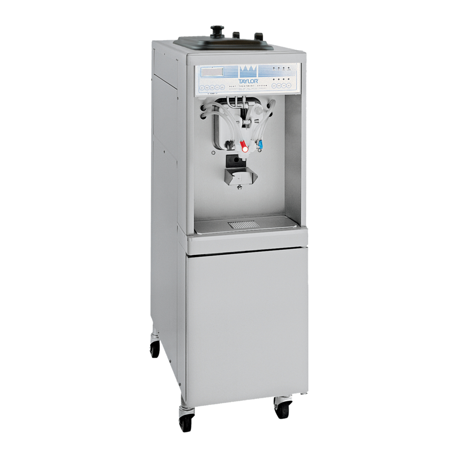
Summary of Contents for Taylor PH61
- Page 1 OPERATOR’S MANUAL Model PH61 Heat Treatment Shake Freezer Original Operating Instructions 8/1/07 (Original Publication) 048119-M (Updated 8/21/2020)
- Page 2 Note: Only instructions originating from the factory or its authorized translation representative(s) are considered to be the original set of instructions. © 2008 Taylor Company 048119-M Any unauthorized reproduction, disclosure, or distribution of copies by any person of any portion of this work may be...
-
Page 3: Table Of Contents
Model PH61 ........ - Page 4 Table of Contents Section 6: Operating Procedures Equipment Setup ........... . . 6-1 Freezing Cylinder Assembly .
-
Page 5: Section 1: To The Installer
Taylor distributor. All repairs must be performed by a Taylor service This machine is made using USA sizes of hardware. All technician. metric conversions are approximate and vary in size. -
Page 6: Air-Cooled Machines
device with a contact gap of at least 0.125 in. (3 mm) in the external installation. • Machines that are permanently connected to To the Installer Model PH61... -
Page 7: Beater Rotation
• If the supply cord is damaged, it must be replaced by a Taylor service technician to avoid CAUTION! Use only approved refrigerant a hazard. listed on the machine's data label or authorized through a •... - Page 8 TO THE INSTALLER Notes: To the Installer Model PH61...
-
Page 9: Section 2: To The Operator
Taylor distributor. The user is responsible for delivering the machine to the Note: Your Taylor warranty is valid only if the parts are appropriate collection facility, as specified by your local authorized Taylor parts, purchased from the local code. -
Page 10: Compressor Warranty Disclaimer
It should also be noted that Taylor does not warrant the refrigerant used in its equipment. For example, if the refrigerant is lost during the course of ordinary service to... -
Page 11: Section 3: Safety
Safety Section 3 We at Taylor Company are concerned about the safety of the operator at all times when they are coming in contact with the machine and its parts. Taylor makes every effort WARNING! This machine must NOT be... - Page 12 Failure to follow these instructions can result in personal injury or damage to the machine. Failure to follow these instructions may result in electrocution. Contact your local authorized Taylor distributor for service. WARNING! DO NOT attempt to draw product or disassemble the machine during the Heat Treatment cycle (if equipped).
- Page 13 Noise Level: Airborne noise emission does not exceed 78 dB(A) when measured at a distance of 39 in. (1.0 m) from the surface of the machine and at a height of 62 in. (1.6 m) from the floor. Safety Model PH61...
- Page 14 SAFETY Notes: Safety Model PH61...
-
Page 15: Model Ph61
Operator Parts Identification Section 4 Model PH61 Figure 4-1 Operator Parts Identification Model PH61... - Page 16 OPERATOR PARTS IDENTIFICATION Model PH61 Parts Identification Item Description Part No. Item Description Part No. Kit A.-Cover-Hopper X65369 Caster-4" SWV 5/8 Stem W/Brake 034081 Agitator A.-Mix Hopper-20 X44797 Door A.-Syrup Cabinet X45325 Pump A.-Mix Simplified Shake X57028-14 Tank-SYR-4·QT 045533 (See Page 4-5)
-
Page 17: Beater And Door Assembly
OPERATOR PARTS IDENTIFICATION Beater and Door Assembly Figure 4-2 Operator Parts Identification Model PH61... - Page 18 O-ring - Freezer Door 033493 Blade A.-Spinner X41895 Door A.-1 SPT-4 FLV-HT X55724-SER Cap-Restrictor 033107 Handscrew (Stud Nut) 034034 Beater A.-Shake X50958 O-ring - Pivot Pin 016272 Plug-Syrup Hole 026278 Pin A.-Pivot X22820 O-ring 024278 Handle-Draw Valve 034003 Operator Parts Identification Model PH61...
-
Page 19: X57028-14 Pump A.-Mix Simplified
O-ring-Pkg *25 per Bag* 008904 Cap-Valve Body Shake 056873-14 Clip-Retainer-Mix Pump 044641 Gasket-Simplified Pump Valve 086097 Tube A.-Feed-Hopper- Shake X56522 Adaptor-Mix Inlet-Shake- Blue 054944 Ring-Check-Feed-Tube 056524 O-ring Pkg 016132 Sleeve A.-Mix Pump X44761 Pin-Cotter-Hairpin-1/8 Dia 044731 Operator Parts Identification Model PH61... -
Page 20: Accessories
Kit A.-Parts Tray SIMPL PMP X58447 (Consists of 056525 & 044118 Lubricant-Taylor Hi-Perf. 048232 Trays - see parts list, page No Tag) Pail-10 Qt. 013163 Kit A.-Accessory PH61 X66408 Bottle A.-Squeeze X45080 Consists of: Tool-Shaft-Drive Pump HPR/LVB 047919 X44797 Agitator, X54704 Cap, ... -
Page 21: X44127 Brush A.-Package-Ht-Ss
Yellow Bristle Brush 039719 White Bristle Brush (1” x 2”) 013073 White Bristle Brush (3” x 7”) 023316-SS White Bristle Brush (1-1/2” x 3”) 014753 Brush-Pump Spout 054068 White Bristle Brush (1/2” x 3”) 033059 Operator Parts Identification Model PH61... -
Page 22: Syrup Tank
Tube-Dip Syrup Tank 015441-7 Valve A.-QD Plug 021081-2 O-ring .291 ID 018550 Insert-QD Plug Valve 021081-1 Washer-1/4 Flare 018595 Decal-Set of 4 Syrup Flav 021523 **Not used on chocolate. Decal-Syrup Tank 045533-1 Socket-QD C02 021524 Operator Parts Identification Model PH61... -
Page 23: Section 5: User Interface
To better communicate in the international arena, the words on many of our operator switches and buttons HEAT MODE CLEAN MANUALLY have symbols to indicate their functions. Your Taylor machine is designed with these international symbols. The following chart identifies the symbol definitions used CHOCOLATE STRAWBERRY on the operator switches. -
Page 24: Power Switch
During a soft Once the system has initialized, the SAFETY TIMEOUT lock condition, all four lights will stop flashing once the screen is displayed, and the alarm is turned on. machine has been placed in a heat cycle. User Interface Model PH61... - Page 25 The following information is given the machine is operating in the Wash and Pump modes, the ° ° temperature of the mix hopper is 40 F (4.4 C), and the machine needs to be brush-cleaned on October 31st. User Interface Model PH61...
- Page 26 All four LEDs on the front of the freezer will illuminate. Press the SEL keypad. The next display is the screen that will appear after the failure message. To comply with health codes, heat treatment system freezers must complete a heat User Interface Model PH61...
-
Page 27: Operator Menu
OFF position. Call a service technician. Once the freezer is unlocked by starting a heat treatment cycle, only the HEAT MODE LED will light. If the freezer is unlocked by brush-cleaning, the MIX LOW and MIX OUT LEDs will light. User Interface Model PH61... - Page 28 When the SEL key is pressed, the previous LCD screen will appear to allow for correction of the entry. The controller will not advance to the Daylight Saving Time screen until a valid date is entered. User Interface Model PH61...
- Page 29 Pressing the SEL key a third time displays the bill of material number and serial number for the machine. Pressing the SEL key from this screen returns the display Note: Draws are counted during the Auto mode of to the OPERATOR MENU. operation only. User Interface Model PH61...
- Page 30 Standby mode and returns to the was completed or terminated. OPERATOR MENU. Pressing the SEL key returns the display to the OPERATOR MENU. User Interface Model PH61...
-
Page 31: Section 6: Operating Procedures
When lubricating parts, use an approved food (HARD LOCK or SOFT LOCK, etc.) before performing grade lubricant (example: Taylor Lube HP). opening procedures. If all four LEDs on the front of the machine are lit, the machine is locked. (See Figure 6-1.) - Page 32 Tighten equally in a crisscross pattern to ensure the back of the beater assembly into the freezing cylinder door is secured. Do not overtighten. and connect the drive hole with the driveshaft. (See Figure 6-8.) (See Figure 6-6.) Operating Procedures Model PH61...
- Page 33 Important! Inspect to see that the spinner shaft seal is correctly installed in the groove. A worn, missing, or improperly installed spinner shaft seal will cause product leakage out the top of the draw valve. (See Figure 6-10.) Figure 6-12 Operating Procedures Model PH61...
- Page 34 The spinner blade must be aligned and engaged to the driven spinner at the bottom. This allows the spinner shaft to raise high enough to be engaged into the spinner coupling at the top. (See Figure 6-18.) Figure 6-15 Operating Procedures Model PH61...
-
Page 35: Mix Hopper Assembly
2. Assemble the piston. Slide the red O-ring into the groove of the piston. Do not lubricate the O-ring. (See Figure 6-22.) Figure 6-19 19. Snap the restrictor cap over the end of the door spout. (See Figure 6-20.) Figure 6-22 Figure 6-20 Operating Procedures Model PH61... - Page 36 5. Assemble the valve cap. Slide the red O-ring into the groove of the valve cap. Do not lubricate the O-ring. (See Figure 6-25.) Figure 6-28 Note: The adapter must be positioned into the notch Figure 6-25 located at the end of the pump cylinder. Operating Procedures Model PH61...
- Page 37 Thoroughly lubricate the O-rings and shaft. Do not lubricate the hex end of the shaft. (See Figure 6-33.) Figure 6-30 11. Install one red O-ring on each end of the mix feed tube, and thoroughly lubricate. (See Figure 6-31.) Figure 6-33 Operating Procedures Model PH61...
-
Page 38: Sanitizing
Secure the pump in place by slipping the pump clip over the collar of the pump, making sure the clip fits into the grooves in the collar. (See Figure 6-35.) Figure 6-36 Operating Procedures Model PH61... -
Page 39: Priming
Figure 6-38 Note: If the agitator paddle stops turning during normal operation, with sanitized hands, remove the agitator from the agitator driveshaft housing and brush-clean with sanitizing solution. Install the agitator back onto the agitator driveshaft housing. Operating Procedures Model PH61... -
Page 40: Daily Closing Procedures
5. Fill the hopper with fresh mix and place the mix 2. Remove the agitator from the mix hopper and the hopper cover in position. restrictor cap from the freezer door spout. Note: Use only fresh mix when priming the freezer. 6-10 Operating Procedures Model PH61... - Page 41 Figure 6-43 Important! If you do not install the agitator correctly, the Figure 6-45 machine will fail the heat cycle and will lock out in the morning. 11. Remove the syrup lines from the freezer door. 6-11 Operating Procedures Model PH61...
- Page 42 WASH key to place the freezer in the Off mode to allow a brush-clean of the machine. Figure 6-47 16. Install the syrup hole plugs in the syrup ports in the freezer door. (See Figure 6-48.) 6-12 Operating Procedures Model PH61...
-
Page 43: Daily Opening Procedures
Standby mode. Figure 6-51 2. Prepare a small amount of an approved 100 ppm ® sanitizing solution (example Kay-5 ). Use warm water and follow the manufacturer's specifications. 6-13 Operating Procedures Model PH61... -
Page 44: Syrup System
8. Using a clean, sanitized towel wipe down the freezer door and area around the bottom of the freezer door. 9. Install the shake cup holder, the front drip tray, and the splash shield. Figure 6-55 6-14 Operating Procedures Model PH61... - Page 45 (See Figure 6-59.) Figure 6-57 3. Remove the syrup tank from the compartment. Remove the syrup tank lid by lifting up on the locking Figure 6-59 lever. Fill the syrup tank with syrup to the indicating 6-15 Operating Procedures Model PH61...
- Page 46 (See Figure 6-65.) pockets from the syrup line. When a steady stream of syrup is flowing into the cup, press the CAL keypad to stop the syrup flow. Discard the syrup in the cup. (See Figure 6-63.) 6-16 Operating Procedures Model PH61...
-
Page 47: Closing Procedures
O-ring on each syrup line fitting. (See Figure 6-66.) Important! This procedure must be completed every 14 days. ALWAYS FOLLOW LOCAL HEALTH CODES. To disassemble the PH61, the following items will be needed: • Two pails for cleaning and sanitizing •... -
Page 48: Draining Product From The Freezing Cylinder
PUMP keys, canceling the Wash and Pump modes, machine is in the Wash mode. and close the draw valve. Discard this product. 2. With a pail beneath the door spout, press the WASH (See Figure 6-70.) key. (See Figure 6-72.) 6-18 Operating Procedures Model PH61... -
Page 49: Cleaning And Sanitizing
These criteria will be met when the machine is properly 7. Once the cleaning solution stops flowing from the brush-cleaned. door spout, close the draw valve and press the WASH key, canceling the Wash mode. 6-19 Operating Procedures Model PH61... - Page 50 O-ring(s) should 24-hours prior to a 14 day lockout. The four mode LEDs be replaced or properly lubricated. will return to their normal function when the unit is unlocked. 6-20 Operating Procedures Model PH61...
-
Page 51: Brush Cleaning
10. Wipe all exterior surfaces of the freezer with a clean, sanitized towel. Figure 6-77 5. Using the black brush, clean the drive hub opening in the rear wall of the mix hopper. (See Figure 6-78.) 6-21 Operating Procedures Model PH61... -
Page 52: Sanitizing The Syrup Systems
10. Repeat this procedure for all syrup lines. air-dry. 11. Place the power switch in the OFF position. 9. Repeat this procedure for all the syrup tanks. 6-22 Operating Procedures Model PH61... -
Page 53: Section 7: Operator Checklist
Too strong of a solution may damage maintenance purposes. Deteriorated or cracked the parts, and too weak of a solution will not do an water lines should be replaced only by a Taylor adequate job of cleaning or sanitizing. sevice technician. -
Page 54: Winter Storage
On water-cooled freezers, disconnect the water supply. Use air pressure to blow out any water remaining in the condensers. Your local Taylor distributor can perform this service for you. Wrap detachable parts of the freezer (such as beater assembly and freezer door) and place in a protected, dry place. -
Page 55: Section 8: Troubleshooting Guide
A barrel or hopper thermistor is a. Call a service technician. appears on the LCD. faulty. b. The freezer must be disassembled and b. More than 14-days since the last brush-cleaning. brush-cleaned every 14-days. Troubleshooting Guide Model PH61... - Page 56 Bad scraper blades. f. Replace the scraper blades. g. The viscosity control is set too g. Call a service technician. warm. h. Brush-clean the pump components and h. Air passage is blocked in the pump. re-assemble. Troubleshooting Guide Model PH61...
- Page 57 Clean the valve. 5 seconds. valve. c. Plugged syrup line fitting at freezer c. Clean the syrup line fitting. door connection. d. Verify that the proper syrup d. Make the proper syrup selection. selection was made. Troubleshooting Guide Model PH61...
- Page 58 26.Shakes have air a. Syrup valves are clogged. a. Disassemble and clean the syrup valves. bubbles in them. 27.Mix low and mix out a. Milkstone buildup in the hopper. a. Clean hoppers thoroughly. probes are not functioning. Troubleshooting Guide Model PH61...
- Page 59 Restrictor Cap-Shake Mix Feed Tube O-ring Pump O-Ring Mix Inlet Tube O-ring Mix Feed Tube Check Ring Air Inlet Fitting Seal Pump Driveshaft O-ring Pump Valve Gasket Brush A.-Package-HT-SS Inspect and replace when Minimum necessary. Parts Replacement Schedule Model PH61...
- Page 60 PARTS REPLACEMENT SCHEDULE Notes: Parts Replacement Schedule Model PH61...
- Page 61 In addition, during the one (1) year period commencing on the date of original installation of the Product, Taylor will also provide, through an authorized Taylor distributor or service agency, all service needed to replace the failed defective part at no charge for the service.
- Page 62 7. Failure, damage, or repairs due to faulty installation, misapplication, abuse, no or improper servicing, unauthorized alteration, or improper operation or use as indicated in the Taylor Operator’s Manual, including but not limited to the failure to use proper assembly and cleaning techniques, tools, or approved cleaning supplies.
- Page 63 LEGAL REMEDIES The owner must notify Taylor in writing, by certified or registered letter to the following address, of any defect or complaint with the Product, stating the defect or complaint and a specific request for repair, replacement, or other correction of the Product under warranty, mailed at least thirty (30) days before pursuing any legal rights or remedies.
- Page 64 LIMITED WARRANTY ON EQUIPMENT Notes: 10-4 Limited Warranty on Equipment Model PH61...
- Page 65 Taylor warrants the Parts against failure due to defect in materials or workmanship under normal use and service as follows. All warranty periods begin on the date of original installation of the Part in the Taylor unit. If a Part fails due to defect during the applicable warranty period, Taylor, through an authorized Taylor distributor or service agency, will provide a new or remanufactured Part, at Taylor’s option, to replace the failed defective Part at no charge for the Part.
- Page 66 Taylor. 5. Replacement of wear items designated as Class “000” Parts in the Taylor Operator’s Manual, as well as any release sheets and clips for the Product’s upper platen assembly.
- Page 67 LEGAL REMEDIES The owner must notify Taylor in writing, by certified or registered letter to the following address, of any defect or complaint with the Part, stating the defect or complaint and a specific request for repair, replacement, or other correction of the Part under warranty, mailed at least thirty (30) days before pursuing any legal rights or remedies.
- Page 68 LIMITED WARRANTY ON PARTS Notes: 11-4 Limited Warranty on Parts Model PH61...
Need help?
Do you have a question about the PH61 and is the answer not in the manual?
Questions and answers