Alpha ESS STORION-T30 Installation Manual
Energy storage system(ess) indoor,with m48112-s
Hide thumbs
Also See for STORION-T30:
- Installation, operation & maintenance manual (59 pages) ,
- Operation & maintenance manual (25 pages)
Table of Contents
Advertisement
Quick Links
@AlphaESS
@AlphaEnergyStorageSystem
Alpha ESS Co., Ltd.
+86 513 806 068 91
info@alpha-ess.com
www.alpha-ess.com
JiuHua Road 888, High-Tech Industrial Development
Zone 226300 Nantong City, Jiangsu Province
Alpha ESS Europe GmbH
+49 610 3459 1601
europe@alpha-ess.de
www.alpha-ess.de
Paul-Ehrlich-Straße 1a 63225 Langen
Alpha ESS Australia Pty. Ltd.
+61 1300 968 933
australia@alpha-ess.com
www.alpha-ess.com.au
Unit 1, 2 Ralph Street Alexandria NSW 2015
Alpha ESS UK Co., Ltd
uk@alpha-ess.com
Drake House, Long Street, Dursley, gl11 4hh
@alpha_ess
@AlphaESS
Alpha ESS Suzhou Co., Ltd.
+86 512 6828 7609
info@alpha-ess.com
www.alpha-ess.com
Building 10-A, Canal Town Industrial Park,
99 Taihu E Rd, Wuzhong District, Suzhou 215000
Alpha ESS Italy S.r.l.
+39 599 239 50
info@alpha-ess.it
www.alpha-ess.it
Via Loda,17-41013 Castelfranco Emilia(MO)
Alpha ESS Korea Co., Ltd
+82 64 721 2004
korea@alpha-ess.com
2F, 19-4, Nohyeong 11-gil, Jeju-si, Jeju-do,
Republic of Korea
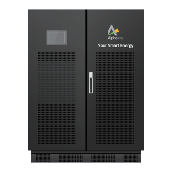
INSTALLATION MANUAL OF
ENERGY STORAGE SYSTEM(ESS)
STORION-T30 (INDOOR,WITH M48112-S)
V01
Advertisement
Table of Contents

Related Manuals for Alpha ESS STORION-T30


Summary of Contents for Alpha ESS STORION-T30
- Page 1 INSTALLATION MANUAL OF ENERGY STORAGE SYSTEM(ESS) @AlphaESS @alpha_ess @AlphaESS @AlphaEnergyStorageSystem STORION-T30 (INDOOR,WITH M48112-S) Alpha ESS Co., Ltd. Alpha ESS Suzhou Co., Ltd. +86 512 6828 7609 +86 513 806 068 91 info@alpha-ess.com info@alpha-ess.com www.alpha-ess.com www.alpha-ess.com JiuHua Road 888, High-Tech Industrial Development...
-
Page 2: Table Of Contents
CONTENT Copyright Statement This manual is under the copyright of Alpha ESS Co., Ltd, with all rights reserved. Please INTRODUCTION keep the manual properly and operate in strict accordance with all safety and operating 1.1 Brief Introduction instructions in this manual. Please do not operate the system before reading through the manual. -
Page 3: Start-Up And Operation
INTRODUCTION Introduction 4.4.4 Backup box (If available) 1.1 Brief Introduction 4.4.5 Meter Wiring This manual applies for Storion-T30 Li-ion battery energy storage system, mainly 4.4.6 AC Auxiliary Power Cable Connection includes: (1) Safety introduction START-UP AND OPERATION Introduces the product use, operating notes and qualification of operators of T30 Li-ion battery energy storage system. -
Page 4: Safety Instructions
SAFETY INSTRUCTIONS SAFETY INSTRUCTIONS 2.4 Setting of Warning Sign for Safety Safety Instructions While instructing, maintaining and repairing, in case of incorrect operation or accident caused by unrelated personnel nearby, the suggestions below should be followed: 2.1 Manual Keeping Obvious signs should be set at front switch and rear-level switch in case of accidents This manual contains important information about operating the system. -
Page 5: Minimum Personal Protective Equipment
For the safety of operators to the system, personal protective equipment are required. During the operation, following protective equipment are required: The AlphaESS Storion-T30 energy storage system is an on-grid system designed for self-consumption at certain periods or for load shifting. Since it is equipped with an energy storage inverter, the T30 can work in DC/AC mode. -
Page 6: Product Description
3.3.1 PCS 3.3.1.1 Product Instruction Storion-T30-INV is an energy storage inverter. There are three operation modes: grid-tied discharging, charging and off-grid discharging. When the battery voltage connected to T30-INV is within the preset normal voltage range, the inverter can operate under grid-tied discharging, charging and off-grid discharging. -
Page 7: Battery System
PRODUCT DESCRIPTION PRODUCT DESCRIPTION 3.3.1.3 Technical Parameters 3.3.2.1 M48112-S 450 mm Table 3 Inverter parameters Item Description Parameter Remark 165 mm 42 A Max. AC Input Current 400 V Nominal AC Input Voltage 200 ~ 750 V Battery Voltage Range 90 A Max. - Page 8 PRODUCT DESCRIPTION PRODUCT DESCRIPTION The DIP switch of M48112-S defines the serial number. Please see the detailed -20~45 ℃ Transportation/storage description in the following table. temperature range Operating temperature range -10~50 ℃ Table 6 DIP switch definition of M48112-S Communication mode Serial Serial Serial...
-
Page 9: T30 Cabinet
PRODUCT DESCRIPTION PRODUCT DESCRIPTION 3.3.3 T30 cabinet Table 8 HV900112 interface definition Description Description DC in+ AC input (auxiliary power) DC in- AC Air switch (auxiliary power) Grounding point x 4 BMU COM port (CAN) x 2 Moulded case circuit breaker LMU COM port (CAN) LED light Information label... -
Page 10: Installation
INSTALLATION INSTALLATION Installation 4.1 Installation Precautions The following sites are not allowed for installation: A.Sites which are salty and where humid air can penetrate. 411.00022-00 422.50001-00 640.00001-00 810.00035-00 B.Flooded areas. 4 X M12 Hex Nut 8 X M6 20 X Cable Tie 1 X Communication Cable C.Earthquake areas(additional security measures are required here). -
Page 11: Installation
INSTALLATION INSTALLATION Cabinet 1 x Installation manual 1 x Operation and maintenance manual 4.3 Installation Figure 4-2 Installation space 4.3.1 Cabinet Installation 4.3.1.1 Removal When removing the T30-cabinet, a forklift can be used to remove the whole case. Users “≥1,000mm, ensure that the front door of the cabinet can be fully opened. There can lift the device bottom with a forklift or remove the cabinet through the lifting hole on is sufficient space for cold air to enter. -
Page 12: Battery Installation
INSTALLATION INSTALLATION Screws Grounding Screw Figure 4-3 Pushed the baffle plate After opening the cabinet door, the bottom position of the cabinet is shown in Figure 4-3. Then, please loose the baffle plate, rotate the two screws clockwise and push the baffle plate to the direction as shown in the figure. - Page 13 INSTALLATION INSTALLATION 4.4.1.1 Communication Cables Connection Another COM port of HV900112 should be inserted with the terminal residence from system parts list. You can see the detailed information in Figure 4-10. Please refer to the following Take the terminal resistance in figure, connect the the HV900112 parts list and communication cables among...
-
Page 14: System Grounding
INSTALLATION INSTALLATION c.If you need dispatching functionality, you can connect the dispatching module in your own location as shown in Figure 4-11. Line sequence 3B6A of dispatching communication RJ45. RJ45 R J45 1 2 3 4 5 6 7 8 1 2 3 4 5 6 7 8 Pin1: Orange&white Pin2: Orange... -
Page 15: Ac Side-Wiring
INSTALLATION INSTALLATION 4.4.4 Backup box (If available) WARNING Rack and modules need to be grounded reliably! The grounding resistance should be less than Load 4Ω. L1 L2 L3 N 4.4.3 AC Side-Wiring RS485 L1 L2 L3 N Load T30-INV Grid Step 1: Use a phase-sequence meter for measurement, and ensure that the phase Grid Grid... -
Page 16: Object Name
INSTALLATION INSTALLATION Table 12 Ports Description Object Name Description General Load Connect to L1 Power port 1 Connect to L2 Power port 2 Power port 3 Connect to L3 Grid Power port N Connect to N N L3 L2 L1 Inverter Grid CT1 sampling cable wiring... - Page 17 START-UP AND OPERATION CONTACT Start-up and Operation Contact Please refer to the Operation Manual for details. If you have technical problems with our products, please contact the service hotline, contact information is under the IMPRINT catalog at the beginning of this manual. Please provide the following information to help you with the necessary assistance: A.Equipment model B.Serial number...
Need help?
Do you have a question about the STORION-T30 and is the answer not in the manual?
Questions and answers