Festo CPX Series Manual
Multi-axis interface
Hide thumbs
Also See for CPX Series:
- Manual (446 pages) ,
- Electronic manual (232 pages) ,
- Description (156 pages)

Subscribe to Our Youtube Channel
Related Manuals for Festo CPX Series


Summary of Contents for Festo CPX Series
- Page 1 CPX Terminal Manual electronics Multi−Axis Interface CPX−CMXX Manual 564 222 en 0910a [750 490]...
- Page 3 ....... . . 564 222 © (Festo AG & Co. KG, D 73726 Esslingen, Germany, 2009) Internet: http://www.festo.com E−Mail:...
- Page 4 Open DeviceNet Vendor Association. Inc. (ODVA) CC−Link ® is a registered trade mark of Mitsubishi Electric Corp. Interbus ® is a registered trade name of Phoenix Contact GmbH & Co. KG, Blomberg, Germany Festo P.BE−CPX−CMXX−E N en 0910a...
-
Page 5: Table Of Contents
..........2−7 Festo P.BE−CPX−CMXX−E N en 0910a... - Page 6 ......... . . 2−10 2.5.2 Connection with Festo CAN bus plug ......2−11 2.5.3...
- Page 7 ............B−1 Festo P.BE−CPX−CMXX−E N en 0910a...
- Page 8 Contents and general instructions Festo P.BE−CPX−CMXX−E N en 0910a...
-
Page 9: Intended Use
Contents and general instructions Intended use The CPX−CMXX multi−axis interface documented in this manual is intended exclusively for use in Festo CPX terminals for installation in a machine or an automation control system. The multi−axis interface CPX−CMXX permits coordination of... -
Page 10: Target Group
This description is intended exclusively for technicians trained in control and automation technology, who have experience in installing, commissioning, programming and diagnosing positioning systems. Service Please consult your local Festo Service agent if you have any technical problems. VIII Festo P.BE−CPX−CMXX−E N en 0910a... -
Page 11: Important User Instructions
... means that failure to observe this instruction may result in damage to property. The following pictogram marks passages in the text which describe activities with electrostatically sensitive devices: Electrostatically sensitive components: Improper handling can result in damage to components. Festo P.BE−CPX−CMXX−E N en 0910a... - Page 12 Recommendations, tips and references to other sources of information Accessories: Information about necessary or useful accessories for the Festo product. Environment: Information on the environmentally friendly use of Festo products. Text designations Bullet points indicate activities that may be carried out in · any order.
-
Page 13: Safety Instructions
Make sure that no persons are in the operating range of · the drive or any other connected actuators. Do not switch on the compressed air supply until the · system is correctly installed and parameterised. Festo P.BE−CPX−CMXX−E N en 0910a... - Page 14 Do not connect, disconnect or open pressurised tubing. · The tubing must always be vented before removal · (release compressed air). Use suitable protective equipment · (e.g. safety goggles, safety shoes, etc.). Festo P.BE−CPX−CMXX−E N en 0910a...
-
Page 15: Notes On This Description
Description of the configuration, CMXX parameterisation and commissioning of the multi−axis interface CPX−CMXX Description of the Festo Description of the Festo data handling and positioning profile profile FHPP−MAX, which is used for multi−axis movements for communication between (FHPP−MAX), controller and CPX−CMXX. - Page 16 General basic information on the mode of operation, mounting, installing and commissioning of CPX terminals can be found in the CPX system description, type P.BE−CPX−SYS−... Observe also the user documentation of the components used in the CPX terminal. Festo P.BE−CPX−CMXX−E N en 0910a...
-
Page 17: Glossary
Front−end controller as CPX module. Controller integrated into the CPX terminal. CPX module Collective term for the various modules which can be integrated in a CPX terminal. CPX terminal Complete system consisting of CPX modules. Functional earth Festo P.BE−CPX−CMXX−E N en 0910a... - Page 18 The synchronous point−to−point movement is a coordinated multi−axis movement movement with the following characteristics. The positioning times of the axes are adapted to the axis with the greatest positioning time. All axes end their movement simultaneously. Tab. 0/2: Terms and abbreviations Festo P.BE−CPX−CMXX−E N en 0910a...
-
Page 19: System Summary
System summary Chapter 1 1−1 Festo P.BE−CPX−CMXX−E N en 0910a... -
Page 20: Advantages
Connection and display components ....... 1−13 1−2 Festo P.BE−CPX−CMXX−E N en 0910a... - Page 21 CPX fieldbus node or through the CPX−FEC/CPX−CEC controller integrated into the CPX terminal. Communication to the CPX−CMXX is achieved through the Festo FHPP−MAX data profile. The Festo data profile is based on the Festo data profile FHPP, which was expanded for multi−axis operation.
-
Page 22: System Summary
Configuration of two axis groups with up to four axes each is possible. There are 1024 position sets available per axis group. Configuration with the Festo Configuration Tool (FCT). Simple input or teaching of positions in a specified record structure. -
Page 23: Mode Of Operation
CPX−CMXX via a CPX fieldbus node, or a CPX−FEC/CPX−CEC control the movement sequence via the Festo data profile FHPP−MAX. The controller can thereby either specify just the record numbers stored in the CPX−CMXX or separate values for position, velocity and acceleration for each axis. - Page 24 SFC−LAC 1.05 Tab. 1/1: Overview of supported motor controllers (Version: November 2009) A warning message is displayed with higher software versions, but this does not influence the function of the motor controllers. 1−6 Festo P.BE−CPX−CMXX−E N en 0910a...
-
Page 25: Control Possibilities
CPX−FEC or CPX−CEC Communication with the controller takes place with 16−byte input and output data, 8 bytes per axis group. Communication takes place over the Festo data profile FHPP−MAX, see description P.BE−CMXX−FHPP−MAX−SW−... 1−7 Festo P.BE−CPX−CMXX−E N en 0910a... - Page 26 Revision 02 Software status (SW) see type plate Tab. 1/2: Overview of CPX modules (Version: November 2009) Note Also observe the notes on the software version in the documentation for the respective CPX module. 1−8 Festo P.BE−CPX−CMXX−E N en 0910a...
- Page 27 Of which up to 3 gantry axes or up to 4 positioning axis One motor controller per axis One drive per axis One translatory or rotatory axis each Tab. 1/3: Design of a multi−axis system The possible system configurations are explained in chapter 1.5. 1−9 Festo P.BE−CPX−CMXX−E N en 0910a...
- Page 28 CPX−CMXX In this configuration, the sequence control of the CPX terminal is taken over by the CPX−FEC/CPX−CEC. Programming takes place over the Festo data profile FHPP−MAX. The CPX−CMXX takes over multi−axis control in combination with the CPX−FEC/CPX−CEC. Communication between the CPX−CMMX and CPX−FEC/CPX−CEC is carried out over the...
- Page 29 Fig. 1/2: Design of CPX terminal with higher−level controller In this configuration, the sequence control of the CPX terminal is taken over by a higher−level controller. Programming takes place over the Festo data profile FHPP−MAX. The CPX−CMXX takes over multi−axis control in combination with the higher−level controller.
- Page 30 In this configuration, the sequence control of the CPX terminal is taken over by the CPX−FEC/CPX−CEC. Programming takes place over the Festo data profile FHPP−MAX. The CPX−CMXX takes over multi−axis control in combination with the CPX−FEC/CPX−CEC. Communication between the CPX−CMMX and CPX−FEC/CPX−CEC is carried out over the...
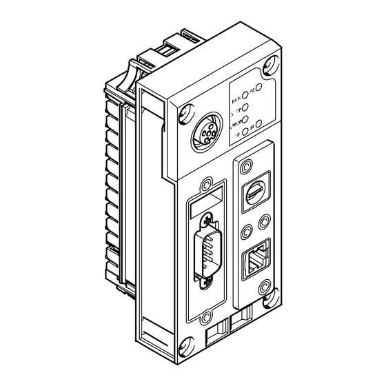
- Page 31 (Selection of the operating mode) RUN/STOP rotary switch DIL switch 2 Ethernet interface (CAN bus termination) (10/100BaseT, RJ45) Interface, reserved Control interface (CAN bus, 9−pin sub−D plug) Fig. 1/4: Connection and display elements on the CPX−CMXX 1−13 Festo P.BE−CPX−CMXX−E N en 0910a...
- Page 32 (yellow) ERROR Error (red) Ethernet connection (green) Control hierarchy is with (yellow) Power system (green) The LEDs RUN 1 and STOP 2 show the status of the RUN/STOP rotary switch. Fig. 1/5: Status LEDs 1−14 Festo P.BE−CPX−CMXX−E N en 0910a...
-
Page 33: Fitting And Installation
Fitting and installation Chapter 2 2−1 Festo P.BE−CPX−CMXX−E N en 0910a... - Page 34 ......... . . 2−10 2.5.2 Connection with Festo CAN bus plug ......2−11 2.5.3...
-
Page 35: General Installation Instructions
· sensitive devices. Information about mounting the CPX terminal can be found in the CPX system description (P.BE−CPX−SYS−...). Information on mounting the components of the multi−axis system can be found in the related components documentation. 2−3 Festo P.BE−CPX−CMXX−EN en 0910a... -
Page 36: Dismantling And Mounting
Dismantle the CPX−CMMX as follows: 1. Loosen the four screws of the CPX−CMXX with a Torx screwdriver of size T10. 2. Pull the CPX−CMXX carefully and without tilting away from the contact rails of the interlinking block. 2−4 Festo P.BE−CPX−CMXX−EN en 0910a... -
Page 37: Mounting
4. Place the screws so that the self−cutting threads can be used. Tighten the screws by hand. 5. Tighten the screws with a size T10 Torx screwdriver with a torque of 0.9 ... 1.1 Nm. 2−5 Festo P.BE−CPX−CMXX−EN en 0910a... -
Page 38: Setting The Switches
CPX−CMXX stopped The STOP LED lights up yellow. 1 ... F CPX−CMXX started. The switch positions 1 ... F have no further function. The RUN LED lights up green. Tab. 2/1: Setting the RUN/STOP rotary switch 2−6 Festo P.BE−CPX−CMXX−EN en 0910a... -
Page 39: Dil Switch
Tab. 2/2: Setting the operating mode Note Check that the setting of the DIL switch is correct before commissioning the CPX−CMXX. Modification to the switch setting is not recognized until the power supply is switched off, then on again. 2−7 Festo P.BE−CPX−CMXX−EN en 0910a... - Page 40 CAN bus termination switched on. DIL 2.1: ON DIL 2.2: OFF All further switch settings are reserved. Tab. 2/3: Setting the CAN bus termination Changes to DIL switch 2 have a direct effect on the CAN bus termination. 2−8 Festo P.BE−CPX−CMXX−EN en 0910a...
-
Page 41: Control Interface
If a motor controller with external voltage supply is connected, CAN Ground (optional), pin 6, on the CPX−CMXX must not be used. FE: Functional earth Tab. 2/4: Pin assignment of the control interface The CPX−CMXX does not provide any voltage for the connected CAN bus slaves via the control interface. 2−9 Festo P.BE−CPX−CMXX−EN en 0910a... -
Page 42: Connecting The Can Bus
Use a twisted, screened 4−core cable as CAN bus line. The CPX−CMXX communicates with the motor controllers via the CAN bus line. If the Festo CAN bus plug is used, a cable diameter of 5−8 mm or 7−10 mm is permitted. Note... -
Page 43: Connection With Festo Can Bus Plug 2−11
You can disconnect the plug from the node without interrupting the bus cable (T−TAP function). Note The clamp strap in the Festo CAN bus plug is connected only capacitively internally with the metal housing of the sub−D plug. This prevents equalizing currents from flowing via the screening of the CAN bus cable (Fig. - Page 44 Bus in Clamp strap for Bus out screening connection Protective cap if connection is not used CAN bus outgoing (OUT) CAN bus incoming (IN) Sub−D plug connected capacitively Fig. 2/2: CAN bus plug from Festo, FBS−SUB−9−BU−2x5POL−B 2−12 Festo P.BE−CPX−CMXX−EN en 0910a...
-
Page 45: Further Connection Possibilities For The Can Bus With Adapters
· interface. Connect the screen. · There are further possibilities to connect the CAN bus with adapters, which can be ordered separately from Festo. M12 adapter 5−pin (protection class IP65) FBA−2−M12−5POL Screw terminal adapter 5−pin (protection class IP20) FBA−1−SL−5POL 2−13... - Page 46 Note Use protective caps or blanking plugs to seal unused · connections. You will then comply with protection class IP65. Order this adapter from Festo (FBA−2−M12−5POL). M12 adapter Pin no. 1. Screening 2. 24 V DC bus (max. 4 A) 3.
- Page 47 CAN bus. The maximum permitted current at the terminals is 4 A. Use cables with a cross sectional area of min. 0.34 mm Order this adapter from Festo (FBA−1−SL−5POL) together with the terminal strip FBSD−KL−2x5POL. Screw terminal Pin no.
-
Page 48: Ethernet Interface
Shield Screening covering Tab. 2/5: Pin allocation for the Ethernet interface Seal an unused Ethernet interface with a suitable cover · (see chapter 2.7). Use suitable plugs for the Ethernet interface · (see chapter 2.7). 2−16 Festo P.BE−CPX−CMXX−EN en 0910a... -
Page 49: Ensuring Protection Classip65/Ip67
Plug Cover FBS−RJ45−8−GS AK−RJ45 Reserved Protective cap interface, M12 ISK−M12 Rotary switch Cover AK−RJ45 DIL switch if connection is not used included in scope of delivery Tab. 2/6: Connections and covers for protection class IP65/IP67 2−17 Festo P.BE−CPX−CMXX−EN en 0910a... - Page 50 2. Fitting and installation 2−18 Festo P.BE−CPX−CMXX−E N en 0910a...
-
Page 51: Commissioning
Commissioning Chapter 3 3−1 Festo P.BE−CPX−CMXX−E N en 0910a... - Page 52 ..........3−14 3.4.3 Configuring and parameterising CPX−CMXX ....3−16 3−2 Festo P.BE−CPX−CMXX−E N en 0910a...
-
Page 53: General Instructions On Commissioning
(e.g. when teaching positions, jogging and homing). Information about commissioning the CPX terminal can be found in the CPX system manual (P.BE−CPX−SYS−...). Information on commissioning the components of the multi−axis system can be found in the related components documentation. 3−3 Festo P.BE−CPX−CMXX−EN en 0910a... -
Page 54: Installing Fct And Fct Plug−Ins
3. Commissioning Preparing configuration and parameterisation To configure and parameterise the CPX−CMXX and motor controller, you need a PC on which the Festo Configuration Tool (FCT) and the respective FCT plug−ins are installed. 3.2.1 Installing FCT and FCT plug−ins Note Installation of the FCT plug−ins of the motor controller is... - Page 55 When installation is completed, you will find the FCT entry in the start menu under Festo Software". The CMXX plug−in is available for setting up new projects as Festo components and is activated automatically when an existing CMXX project is selected. 3−5...
- Page 56 3. Commissioning Deinstallation The CMXX plug−in and the FCT program are disconnected in each case with help of the Software" function in Windows System Control. Follow the instructions in your Windows manual. · 3−6 Festo P.BE−CPX−CMXX−EN en 0910a...
-
Page 57: Parameterisation Of The Connected Motor Controllers
If the CAN bus malfunctions (DIL2.1 termination OFF or separation of the connection), drives can continue to move and cause collisions with severe injuries. Make sure that no persons are in the operating range of · the drive or any other connected actuators. 3−7 Festo P.BE−CPX−CMXX−EN en 0910a... - Page 58 Communication between CPX−CMXX and the motor controllers takes place over the following interface: Parameter Setting Interface CANopen Data profile DS 402 Transmission rate 1 MBit/s CAN address see Tab. 3/2 Tab. 3/1: Parameters for communication 3−8 Festo P.BE−CPX−CMXX−EN en 0910a...
- Page 59 3. Commissioning The CAN address of the axes is established as follows: Axis group Axis CAN address Tab. 3/2: CAN addresses of the axes 3−9 Festo P.BE−CPX−CMXX−EN en 0910a...
-
Page 60: Specific Settings For Cmmx−Xx Motor Controller 3−10
With this setting, when parameterising the CPX−CMXX for all CMMx−xx motor controllers, the transmission factor must be set at 1000 increments/mm or 1000 increments/°, see Online Help for FCT plug−in CPX−CMXX. Tab. 3/3: Specific settings for CMMx−xx motor controller 3−10 Festo P.BE−CPX−CMXX−EN en 0910a... -
Page 61: Specific Settings For Mtr−Dci Motor Unit 3−11
Menu/Tab Parameter Value [Configuration] Controller type SFC−DC−...−CO [Controller] [Interface] CAN address CAN address of the axis, see Tab. 3/2 Bit rate 1 MBit/s Data profile DS 402 Tab. 3/5: Specific settings for SFC−DC motor controller 3−11 Festo P.BE−CPX−CMXX−EN en 0910a... -
Page 62: Specific Settings For Sfc−Lac Motor Controller 3−12
DS 402 Supply voltage only with external" option: An external power supply must be attached to the CAN bus plug; see section 2.4, Tab. 2/4 and P.BE−SFC−LAC−CO−... Tab. 3/6: Specific settings for SFC−LAC motor controller 3−12 Festo P.BE−CPX−CMXX−EN en 0910a... -
Page 63: Configuration Of The Cpx−Cmxx
To connect the PC directly to the CPX−CMXX, use alternatively a crossover cable with RJ45 plug. a patch cable with RJ45 plug. The Ethernet interface of the CPX−CMXX recognises which cable is connected and automatically switches over internally. 3−13 Festo P.BE−CPX−CMXX−EN en 0910a... -
Page 64: Prepare Pc
1. Select the command [Settings][Network connections] in the Windows start menu. The Network connections" window opens. 2. Double click in the Network connections" window on the network connection intended for connection of the CPX−CMXX. The dialog Status of <Your Connection>" opens. 3−14 Festo P.BE−CPX−CMXX−EN en 0910a... - Page 65 Fig. 3/1: Setting the IP address and subnetwork mask Note Write down the network settings of your PC before you change them. 5. Set the network properties of your PC in the dialogue Properties of Internet Protocol (TCP/IP)" and confirm with OK. 3−15 Festo P.BE−CPX−CMXX−EN en 0910a...
-
Page 66: Configuring And Parameterising Cpx−Cmxx 3−16
1. Change the network settings of your PC to the original values. 2. Disconnect the Ethernet connection to the CPX−CMXX. 3. Place a suitable protective cap (see chap. A.2) on the Ethernet interface to reestablish the protection class IP 65/67. 3−16 Festo P.BE−CPX−CMXX−EN en 0910a... -
Page 67: Diagnosis And Error Treatment
Diagnosis and error treatment Chapter 4 4−1 Festo P.BE−CPX−CMXX−E N en 0910a... - Page 68 Other diagnostic information ......4−21 4−2 Festo P.BE−CPX−CMXX−E N en 0910a...
-
Page 69: Overview Of Diagnostics Options
CPX master (CPX−FEC/CPX−CEC or I/O diagnostic CPX fieldbus node) interface or on the CPX−MMI handheld LED indicator The LEDs directly indicate error Fast on−the−spot" Section 4.3 states. recognition of errors Tab. 4/1: Diagnostics options 4−3 Festo P.BE−CPX−CMXX−E N en 0910a... -
Page 70: Errors And Warnings
The motor controllers of the axis group are not switched off. No new positioning task will be accepted. With disturbances of type 2 All motor controllers of the axis group are switched off. No new positioning task will be accepted. 4−4 Festo P.BE−CPX−CMXX−E N en 0910a... -
Page 71: Acknowledging Errors 4−5
Warning Speed cannot be achieved Check the position record · (Limit values of the axes are parameters and the axis incorrect or acceleration path is too parameterisation. short) 4−5 Festo P.BE−CPX−CMXX−E N en 0910a... - Page 72 Warning Warning: Recognised device is not The warning serves as information completely supported that possibly not all functions of the device are supported; operation is still possible. 4−6 Festo P.BE−CPX−CMXX−E N en 0910a...
- Page 73 Invalid product code recognised Check or change the · configuration. Close the device configured in the · FCT plug−in. Invalid firmware recognised Check or change the · configuration. Close the device configured in the · FCT plug−in. 4−7 Festo P.BE−CPX−CMXX−E N en 0910a...
- Page 74 · execution the axis. (Axis command could not be ended in the specified time) Command for inactive axis Check the triggering or · configuration. Command for inactive group Check the triggering or · configuration. 4−8 Festo P.BE−CPX−CMXX−E N en 0910a...
- Page 75 Start a valid position record. · (Number of the selected position record outside the range 1...1024) System error A (CPX error category 104, System_A) Position record memory not Please consult your local Festo · initialised service or (Position records could not be service_international@festo.com.
- Page 76 Error when resetting a node Check the CAN bus and the · configuration of the node involved. Internal error at node start Please consult your local Festo · service or service_international@festo.com. Serious internal error Please consult your local Festo ·...
- Page 77 Error during activation of the Check the motor controller. · "Interpolated position mode" Licence error (CPX error category 144, Licence Error) CoDeSys licence error Please consult your local Festo · service or service_international@festo.com. Tab. 4/2: Error messages of the CMXX 4−11...
-
Page 78: Diagnostics Via Leds
(RUN/STOP switch is in position 0). LED lights up CPX−CMXX not stopped Set the RUN/STOP · (RUN/STOP switch is in switch to 0. LED is off position 1 ... F). Tab. 4/4: LED STOP 4−12 Festo P.BE−CPX−CMXX−E N en 0910a... - Page 79 LED lights up Data transfer active None (LED flashes irregularly) LED flashes Ethernet connection to the Check: · parameterisation PC not OK the connection the IP address LED is off Tab. 4/6: LED TP 4−13 Festo P.BE−CPX−CMXX−E N en 0910a...
- Page 80 Power supply longer than Eliminate the low · 10 ms below the threshold voltage of 17 V. LED flashes Power supply is not on Check the · operating voltage connection. LED is off Tab. 4/8: LED PS 4−14 Festo P.BE−CPX−CMXX−E N en 0910a...
-
Page 81: Diagnosis At The Cpx Terminal
Tab. 4/9. The following sections contain the special features of the presentation for the CPX−specific diagnostics options. Status bits (see section 4.4.1) Diagnosis memory with CPX error categories (I/O diagnosis interface, see section 4.4.2) 4−15 Festo P.BE−CPX−CMXX−E N en 0910a... -
Page 82: Status Bits In The System Status Of The Cpx Terminal
I/O diagnostic interface and the diagnostic memory of the CPX terminal. Diagnostic memory data (I/O diagnostic interface) The specific representation of diagnostic messages of the CPX−CMXX in the diagnostic memory of the CPX terminal occurs as shown in Tab. 4/9. 4−16 Festo P.BE−CPX−CMXX−E N en 0910a... - Page 83 (diagnostic event) [NB] = 0 ... 39 ; most current diagnostic event = 0 Tab. 4/9: Diagnostic memory data of the CPX−CMXX Instructions on diagnosis with the I/O diagnostic interface can be found in the CPX system manual. 4−17 Festo P.BE−CPX−CMXX−E N en 0910a...
- Page 84 = module number (0 ... 47) Description CPX error category Bits 0 ... 7 Value range: 0 ... 255 Remark The CPX error categories of the CPX−CMXX are described in section 4.2. Tab. 4/11: Module error number 4−18 Festo P.BE−CPX−CMXX−E N en 0910a...
- Page 85 CPX−MMI handheld can determine for which axis in which axis group a malfunction is present. The following tables show the definition of the diagnosis channels Channel Axis group Axis number Input channel Tab. 4/12: Definition Diagnosis channels, part 1 4−19 Festo P.BE−CPX−CMXX−E N en 0910a...
- Page 86 4. Diagnosis and error treatment Channel Axis group Axis number Output channel channel Tab. 4/13: Definition of diagnostic channels, part 2 4−20 Festo P.BE−CPX−CMXX−E N en 0910a...
- Page 87 In byte 1 ... 3, each nibble contains one digit of the serial number (BCD encoded) Function no: 784 + m*4 + 0 784 + m*4 + 1 784 + m*4 + 2 784 + m*4 + 3 4−21 Festo P.BE−CPX−CMXX−E N en 0910a...
- Page 88 4. Diagnosis and error treatment 4−22 Festo P.BE−CPX−CMXX−E N en 0910a...
- Page 89 Technical appendix Appendix A A−1 Festo P.BE−CPX−CMXX−E N en 0910a...
- Page 90 ........... . A−5 Device−specific information on the CPX−MMI handheld ....A−6 A−2 Festo P.BE−CPX−CMXX−E N en 0910a...
- Page 91 General technical data of the CPX terminal See CPX system description: Description P.BE−CPX−SYS−... Intrinsic current consumption at nominal operating voltage typ. 85 mA Max. address capacity inputs 16 byte outputs 16 byte A−3 Festo P.BE−CPX−CMXX−E N en 0910a...
- Page 92 Protection class IP65/IP67 only in conjunction with plugs and covers in protection class IP65/IP67. Protocol FHPP−MAX (Festo handling and positioning profile for multi−axis movements) Supported kinematic systems 2−axis gantries (X−Z / Y−Z / X−Y) 3−axis gantries X−Y−Z Total number of axes A−4...
- Page 93 Accessories Please select the appropriate accessories from our catalogue www.festo.com/catalogue/cpx−cmxx. Information on accessories for the CPX terminal can be found in the CPX system description or in the description for the CPX modules used. A−5 Festo P.BE−CPX−CMXX−E N en 0910a...
- Page 94 Fail Safe (F) Warning Incorrect entries in the Force Mode or with the Fail safe function can cause undesired movements and severe personal injury and property damage! The Parameters (P) function is not supported. A−6 Festo P.BE−CPX−CMXX−E N en 0910a...
- Page 95 CPX−CMXX are displayed with the Diagnostics function. Channel fault CH1: Output The diagnostics channel gives the error location, Controller error see section 4.4.3 _____________________________________________________ The CPX error categories are described in section 4.2.3. Back A−7 Festo P.BE−CPX−CMXX−E N en 0910a...
- Page 96 IP Netmask: 255.255.0.0 IP address gateway: 0.0. Revision: 1 Startup: via saved IP par _____________________________________________________ Back Serial number 0x5001FFD1 IP address: 192.168.2.10 IP net mask: 255.255.0.0 IP address gateway: 0.0.0.0 Startup: via saved IP parameters A−8 Festo P.BE−CPX−CMXX−E N en 0910a...
- Page 97 First faulty module 1: CMXX Multi−axis interf Module position and designation Fault number: 107 Controller error Number of the CPX error category _____________________________________________________ Back Designation of the CPX error category A−9 Festo P.BE−CPX−CMXX−E N en 0910a...
- Page 98 Seconds: 57 Milliseconds: 13 Module designation _____________________________________________________ Back ßà Time stamp in the format Days:Hours:Minutes: Seconds: Milliseconds (Days:Hours:Minutes:Seconds: Milliseconds) since switch−on Note Further information on the MMI can be found in the documentation P.BE−CPX−MMI−1−... A−10 Festo P.BE−CPX−CMXX−E N en 0910a...
- Page 99 Index Appendix B B−1 Festo P.BE−CPX−CMXX−E N en 0910a...
- Page 100 ............B−1 B−2 Festo P.BE−CPX−CMXX−E N en 0910a...
- Page 101 ........2−4 B−3 Festo P.BE−CPX−CMXX−E N en 0910a...
- Page 102 XIII Operating mode ......2−7, 2−8 B−4 Festo P.BE−CPX−CMXX−E N en 0910a...
- Page 103 User instructions ....... . . B−5 Festo P.BE−CPX−CMXX−E N en 0910a...
- Page 104 B. Index B−6 Festo P.BE−CPX−CMXX−E N en 0910a...
Need help?
Do you have a question about the CPX Series and is the answer not in the manual?
Questions and answers