Festo CPX Series Brief Description
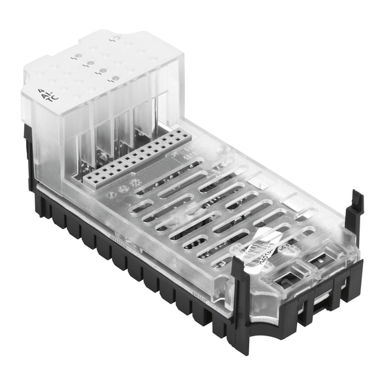
Terminal electrical interface
Hide thumbs
Also See for CPX Series:
- Manual (446 pages) ,
- Electronic manual (232 pages) ,
- Description (156 pages)
Advertisement
Quick Links
Download this manual
See also:
Manual
Advertisement

Subscribe to Our Youtube Channel
Related Manuals for Festo CPX Series


Summary of Contents for Festo CPX Series
- Page 1 Terminal CPX Brief description Electrical interface CPX-CTEL-4- M12-5POL – English 8101605 2018-11c [8101607]...
- Page 2 Translation of the original instructions Documentation on the product For all available product documentation è www.festo.com/pk Copyright: Festo AG & Co. Ruiter Straße 82 73734 Esslingen Germany Internet: http://www.festo.com E-Mail: service_international@festo.com Reproduction, distribution or sale of this document or communication of its contents to others without express authorization is prohibited.
-
Page 3: User Information
• Observe the requirements of IEC 60204-1 for PELV circuits. • Place only a completely mounted and wired CPX ter minal into operation. Note Electrostatically sensitive devices • Do not touch any components. • Observe the handling specifications for electrostatic ally sensitive devices. Festo CPX-CTEL-Z6 2018-11c English... -
Page 4: Connection And Display Components
Status LEDs I-Ports X1 … X4 CPX-specific LEDs Status I-Port X1 … X4 Power system (green) … (green/red) – Connection status OK Power load (green) – Device error – Configuration error or CPX peripheral error (red) compatibility error Festo CPX-CTEL-Z6 2018-11c English... - Page 5 – Illuminated red: CPX starting or CPX error – Off: CPX communication OK X1 … X4 – Illuminates green: device OK – Flashes green: diagnostics – Illuminated red: I-port error – Flashes red: configuration error – Off: no device detected Festo CPX-CTEL-Z6 2018-11c English...
-
Page 6: Installation Instructions
Injury caused by electric shock, damage to machine and to system • Switch supply power off before mounting work. Screws (tightening torque 0.9 … 1.1 Nm) Interlinking block (here with additional power supply, as an example) Electrical interface CPX-CTEL-4-M12-5POL (CTEL master module) Festo CPX-CTEL-Z6 2018-11c English... - Page 7 1. Check seal and sealing surfaces and put the module back on. 2. Tighten the screws by hand in diagonally opposite sequence (tightening torque 0.9 … 1.1 Nm). 3.2 Setting the DIL-switches DIL switch group 1 (I/O mode) DIL switch group 2 (I/O length) Festo CPX-CTEL-Z6 2018-11c English...
- Page 8 16 bytes I/O DIL 2.2: ON (4 bytes per I-Port) DIL 2.1: ON 24 bytes I/O DIL 2.2: OFF (6 bytes per I-Port) DIL 2.1: ON 32 bytes I/O DIL 2.2: ON (8 bytes per I-Port) Festo CPX-CTEL-Z6 2018-11c English...
- Page 9 VAL/OUT Note Operative malfunction due to impermissible cabling. • To connect the devices, use only I-Port connecting cables from the Festo catalogue (è www.festo.com/catalogue). • Comply with the maximum permissible length of 20 m for the I-Port connecting cables. To ensure degree of protection IP65/IP67, the unused I-Port interfaces must be sealed with cover caps.
-
Page 10: Technical Data
Note on materials RoHS-compliant Ambient temperature –5 … +50 °C Storage temperature –20 … +70 °C Moisture/heat 95 %/50 °C Connected devices may only satisfy a lower degree of protection or a smaller temperature range, etc. Festo CPX-CTEL-Z6 2018-11c English... - Page 11 General characteristics Vibration and shock (dependent on mounting) Vibration Wall mounting H-rail mounting Shock Wall mounting H-rail mounting Continuous shock resist Wall mounting ance, H-rail mounting SL = severity level Festo CPX-CTEL-Z6 2018-11c English...
- Page 12 From operating voltage supply 1.6 A (PS) EL/SEN From load voltage supply U (PL) 1.6 A Electrical isolation Between operating voltage supply Yes, with potential-isolated (PS) and load voltage supply supply EL/SEN (PL) Supply PS/PL between the I-Ports Festo CPX-CTEL-Z6 2018-11c English...
- Page 13 Power supply for devices (PS) and load Internal (electronic), supply (PL) separate for each I-port Behaviour after short circuit Dependent on parameter “Behaviour after I-Port short circuit” Reverse polarity protection Separate for each system and load voltage, not separated per I-Port Festo CPX-CTEL-Z6 2018-11c English...
- Page 14 Parameterisation Module parameter Diagnostic behaviour Fail safe (per channel) Forcing (per channel) Idle mode (per channel) Diagnostics Module-oriented diagnostics Undervoltage PS Undervoltage/short circuit of modules Undervoltage PL (via device) I-Port Communication error Short-circuit PS/PL Device error Festo CPX-CTEL-Z6 2018-11c English...
Need help?
Do you have a question about the CPX Series and is the answer not in the manual?
Questions and answers