
Related Manuals for Allied Telesis AT-GS950/8POE


Summary of Contents for Allied Telesis AT-GS950/8POE
-
Page 1: Installation Guide
◆ Installation Guide 613-000989 Rev. A WebSmart Switch AT-GS950/8POE... - Page 2 Allied Telesis, Inc. reserves the right to make changes in specifications and other information contained in this document without prior written notice. The information provided herein is subject to change without notice. In no event shall Allied Telesis, Inc. be liable for any incidental, special, indirect, or consequential damages whatsoever, including but not limited to lost profits, arising out of or related to this manual or the information contained herein, even if Allied Telesis, Inc.
-
Page 3: Electrical Safety And Emissions Standards
Electrical Safety and Emissions Standards This product meets the following standards. Radiated Energy Note: This equipment has been tested and found to comply with the limits for a Class A digital device pursuant to Part 15 of FCC Rules. These limits are designed to provide reasonable protection against harmful interference when the equipment is operated in a commercial environment. -
Page 4: Translated Safety Statements
Translated Safety Statements Important: The indicates that a translation of the safety statement is available in a PDF document titled “Translated Safety Statements” (613-000990) posted on the Allied Telesis website at www.alliedtelesis.com. -
Page 5: Table Of Contents
Product Documentation ... 12 Starting a Management Session ... 13 Safety Symbols Used in this Document ... 14 Where to Find Web-based Guides ... 15 Contacting Allied Telesis ... 16 Online Support ... 16 Email and Telephone Support... 16 Warranty... 16 Returning Products ... - Page 6 Contents Installing the Switch on a Wall ... 41 Resetting the Switch ... 43 Chapter 3: Cabling the Network Ports ... 45 Cable Specifications ... 46 Twisted Pair Cable Specifications ... 46 Optional Transceiver Cable Specifications... 47 Cabling the Switch ... 48 Connecting an RJ-45 Cable ...
- Page 7 Figures Figure 1: AT-GS950/8 POE Switch— Front and Back Panels ...18 Figure 2: SFP Transceiver...25 Figure 3: Port LEDs on an AT-GS950/8POE Switch ...26 Figure 4: Power Workgroup Topology ...30 Figure 5: Collapsed Backbone—Hub Topology...31 Figure 6: Attaching the Rubber Feet ...38 Figure 7: Removing the Feet ...39...
- Page 8 Figures...
- Page 9 Tables Table 1: Safety Symbols ...14 Table 2: IEEE 802.3af Class vs. Power Levels ...23 Table 3: PoE LEDs ...26 Table 4: Twisted Pair Port LEDs ...27 Table 5: SFP Slot LED ...27 Table 6: System LED ...28 Table 7: Twisted Pair Cabling and Distances ...46 Table 8: MDI Pin Signals - 10 or 100 Mbps ...65 Table 9: MDI-X Pin Signals - 10 or 100 Mbps ...65 Table 10: Pin Signals - 1000 Mbps ...66...
- Page 10 Tables...
-
Page 11: Preface
Preface This guide contains the installation instructions for the AT-GS950/8POE Gigabit Ethernet WebSmart Switch. This preface contains the following sections: “Product Documentation” on page 12 “Starting a Management Session” on page 13 “Safety Symbols Used in this Document” on page 14 “Where to Find Web-based Guides”... -
Page 12: Product Documentation
Preface Product Documentation For overview information about the software features of the AT-GS950/ 8POE Gigabit Ethernet WebSmart Switch, refer to the AT-S101 Management Software User’s Guide (P/N 613-000985). -
Page 13: Starting A Management Session
AT-GS950/8POE Gigabit Ethernet WebSmart Switch Installation Guide Starting a Management Session For instructions that describe how to start a web management session on an AT-GS950/8POE switch, refer to the AT-S101 Management Software User’s Guide. -
Page 14: Safety Symbols Used In This Document
Preface Safety Symbols Used in this Document This document uses the safety symbols defined in Table 1. Symbol Table 1. Safety Symbols Meaning Caution Performing or omitting a specific action may result in equipment damage or loss of data. Warning Performing or omitting a specific action may result in electrical shock. -
Page 15: Where To Find Web-Based Guides
AT-GS950/8POE Gigabit Ethernet WebSmart Switch Installation Guide Where to Find Web-based Guides The installation and user guides for all Allied Telesis products are available in portable document format (PDF) on our web site at www.alliedtelesis.com. You can view the documents online or download... -
Page 16: Contacting Allied Telesis
This section provides Allied Telesis contact information for technical support as well as sales and corporate information. Online Support You can request technical support online by accessing the Allied Telesis Knowledge Base: www.alliedtelesis.com/support/kb.aspx. You can use the Knowledge Base to submit questions to our technical support staff and review answers to previously asked questions. -
Page 17: Chapter 1: Overview
Chapter 1 Overview This chapter describes the AT-GS950/8POE switch. This chapter contains the following sections: “Introduction” on page 18 “10/100/1000Base-T Twisted Pair Ports” on page 20 “Power over Ethernet” on page 22 “Redundant Twisted Pair Ports” on page 24 “SFP Transceiver Slots” on page 25 “LEDs”... -
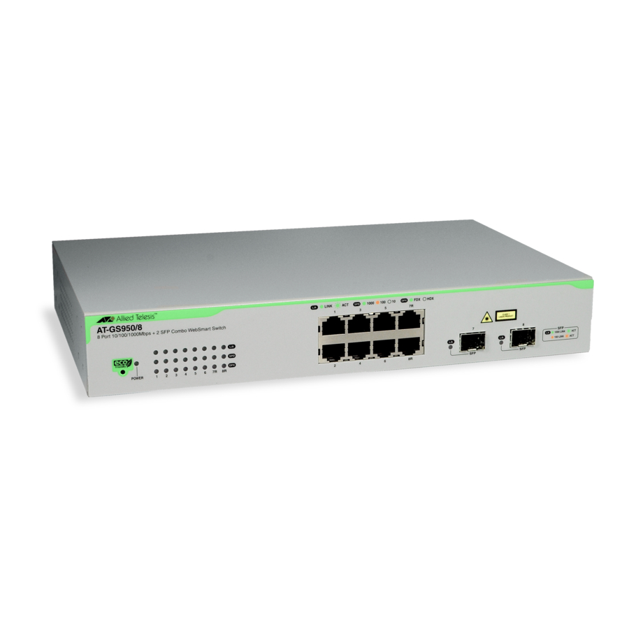
Page 18: Figure 1: At-Gs950/8 Poe Switch— Front And Back Panels
Gigabit ports. Figure 1 shows the front and back panels of the AT-GS950/8POE switch. This switch supports auto-negotiation and auto MDI/MDI-X on all local ports. The AT-GS950/8POE switch is a WebSmart switch that is available through a remote-web-based management session with a factory installed IP address. - Page 19 AT-GS950/8POE Gigabit Ethernet WebSmart Switch Installation Guide PoE feature conforms to IEEE802.3af Data Terminal Equipment (DTE) Supports backpressure flow control at half-duplex and IEEE802.3x at full-duplex Head of Line (HOL) blocking prevention Web management with a pre-assigned IP address of 192.168.1.1...
-
Page 20: 10/100/1000Base-T Twisted Pair Ports
Chapter 1: Overview 10/100/1000Base-T Twisted Pair Ports This section describes the twisted pair ports on the switches. Connector Type The ports are 8-pin RJ-45 connectors that use four pins at 10 or 100 Mbps and all eight pins at 1000 Mbps. For the pin assignments, refer to “RJ-45 Twisted Pair Port Pinouts”... -
Page 21: Cable Type
10 or 100 Mbps in the MDI configuration and Table 9 on page 65 for the MDI-X configuration. For port pinouts when a twisted pair port operates at 1000 Mbps, refer to Table 10 on page 66. AT-GS950/8POE Gigabit Ethernet WebSmart Switch Installation Guide... -
Page 22: Power Over Ethernet
Chapter 1: Overview Power over Ethernet The four of the twisted pair ports on the AT-GS950/8POE switch feature Power over Ethernet (PoE) which is a mechanism for supplying power to network devices over the same twisted pair cables used to carry network traffic. -
Page 23: Power Budgeting
Power Budgeting The AT-GS950/8POE switch provides a maximum of 15.4 W of power per port on four of the eight ports for a total power consumption of 62 W, while at the same time furnishing standard 10/100 Mbps Ethernet functionality. -
Page 24: Redundant Twisted Pair Ports
Chapter 1: Overview Redundant Twisted Pair Ports Two of the twisted pair ports on the AT-GS950/8POE switch are paired with SFP slots. The twisted pair ports are identified with the letter “R” for “Redundant” as part of their number on the faceplate of the unit. Ports 7 and 8 are the redundant ports. -
Page 25: Sfp Transceiver Slots
Ethernet SFP transceivers that interconnect network devices over large distances using fiber optic cable. Figure 2 illustrates an SFP transceiver. AT-GS950/8POE Gigabit Ethernet WebSmart Switch Installation Guide Figure 2. SFP Transceiver Note For a list of supported SFP transceivers, contact your Allied Telesis sales representative. -
Page 26: Leds
GS950/8 POE switch. PoE LEDs The AT-GS950/8POE switch has four PoE ports and four corresponding PoE LEDs. The PoE LEDs signal a connection to a powered device and if the port exceeds its power budget. The PoE LEDs apply to ports 1 through 4. -
Page 27: 10/100/1000Base-T Twisted Pair Port Leds
7R through 8R. Table 4 describes the LEDs for the 10/100/1000Base-T twisted pair ports. SFP LEDs Both SFP transceiver slots on the AT-GS950/8POE switch have one L/A (link/activity) LED which applies to ports 7 and 8. See Table 5 for a description. -
Page 28: System Led
Chapter 1: Overview System LED There is one system LED on the front panel of the switch. It is the POWER LED which indicates whether or not the switch is receiving power. See Table 6 for a description. POWER Table 6. System LED State The switch is not receiving power. -
Page 29: Power Supply
AT-GS950/8POE Gigabit Ethernet WebSmart Switch Installation Guide Power Supply The AT-GS950/8POE switch has an internal power supply with a single AC power supply socket on the back panel which features autoswitch AC inputs. To power the switch on or off, connect or disconnect the power cord provided with the switch. -
Page 30: Figure 4: Power Workgroup Topology
Legend 100 Mbps 1000 Mbps Collapsed In the topology illustrated in Figure 5 on page 31, the AT-GS950/8POE switch is connected to managed and unmanaged Ethernet switches to Backbone form a collapsed backbone topology. The AT-GS950/8POE switch functions as the focal point of the network by transferring Ethernet frames between switches. -
Page 31: Figure 5: Collapsed Backbone—Hub Topology
8 Port 10/100/1000Mbps + 2 SFP Combo WebSmart Switch PORT ACTIVITY 1000 LINK 100 LINK RESET POWER AT-GS900/16 Switch Legend 10 Mbps 100 Mbps 1000 Mbps AT-GS950/8POE Gigabit Ethernet WebSmart Switch Installation Guide AT-GS900/24 Switch Figure 5. Collapsed Backbone—Hub Topology CLASS 1 LASER PRODUCT 100/1000Base-X 1352 AT-GS900/8E Switch... - Page 32 Chapter 1: Overview...
-
Page 33: Chapter 2: Installing The Hardware
Chapter 2 Installing the Hardware This chapter provides procedures to install an AT-GS950/8POE switch on a desktop, in a rack, and on a wall as well as how to reset the switch. The chapter contains the following sections: “Reviewing Safety Precautions” on page 34 “Selecting a Site for the Switch”... -
Page 34: Reviewing Safety Precautions
Note indicates that a translation of the safety statement is available in a PDF document titled “Translated Safety Statements” (613-000990) posted on the Allied Telesis website at www.alliedtelesis.com. Warning: Class 1 Laser product. Warning: Do not stare into the laser beam. - Page 35 AT-GS950/8POE Gigabit Ethernet WebSmart Switch Installation Guide All Countries: Install product in accordance with local and National Electrical Codes. Circuit Overloading: Consideration should be given to the connection of the equipment to the supply circuit and the effect that overloading of circuits might have on overcurrent protection and supply wiring.
-
Page 36: Selecting A Site For The Switch
Chapter 2: Installing the Hardware Selecting a Site for the Switch Observe the following requirements when choosing a site for your switch: If you plan to install the switch in an equipment rack, ensure that the rack is secured safely and that it will not tip over. Devices in a rack should be installed starting at the bottom, with the heavier devices near the bottom of the rack. -
Page 37: Unpacking A Switch
2. Place the switch on a level, secure surface. 3. Make sure the following components are included in your switch package. If any item is missing or damaged, contact your Allied Telesis sales representative for assistance. AT-GS950/8POE Gigabit Ethernet WebSmart Switch Installation Guide Note Store the packaging material in a safe location. -
Page 38: Installing The Switch On A Desktop
Note For cabling information, see Chapter 3, “Cabling the Network Ports” on page 45. LINK LINK 1000 ACTIVITY PORT AT-GS950/8POE Switch WebSmart Combo 10/100/1000Mbps Port POWER RESET 1355... -
Page 39: Installing The Switch In An Equipment Rack
4. Attach a rack-mount bracket to one side of the switch using four of the screws that come with the switch, as shown in Figure 8 on page 40. AT-GS950/8POE Gigabit Ethernet WebSmart Switch Installation Guide Note Steps 1, 2, and 3 are optional. These steps provide instructions on how to remove the snap-on plastic feet from the bottom of a switch. -
Page 40: Figure 8: Attaching Rack-Mount Brackets
Chapter 2: Installing the Hardware 5. Install the second rack-mount bracket on the other side of the switch 6. Mount the switch in a 19-inch rack using standard screws (not Figure 8. Attaching Rack-Mount Brackets with the four remaining screws. provided), as shown in Figure 9. -
Page 41: Installing The Switch On A Wall
4. Attach the two rack-mounting brackets (provided) to the sides of the switch using the eight flathead Phillips screws (provided), as shown in Figure 10. AT-GS950/8POE Gigabit Ethernet WebSmart Switch Installation Guide Note Steps 1, 2, and 3 are optional. These steps provide instructions on how to remove the snap-on plastic feet from the bottom of a switch. -
Page 42: Figure 11: Attaching The Switch To The Wall
Chapter 2: Installing the Hardware 5. Place the switch on the wall. Then mount the switch using the four #10-32 Phillips screws which are shipped with the product as shown in Figure 11. Figure 11. Attaching the switch to the wall Note For cabling information, see Chapter 3, “Cabling the Network Ports”... -
Page 43: Resetting The Switch
You may need to reset the switch after upgrading the firmware or after you have made a configuration change that requires resetting the switch to activate the change. To reset the AT-GS950/8POE switch, perform the following procedure: 1. Locate the RESET button which is on the right hand side of the faceplate. - Page 44 Chapter 2: Installing the Hardware...
-
Page 45: Chapter 3: Cabling The Network Ports
Chapter 3 Cabling the Network Ports This chapter contains guidelines and instructions for attaching network cables to an AT-GS950/8POE switch. This chapter contains the following sections: “Cable Specifications” on page 46 “Cabling the Switch” on page 48 “Connecting an RJ-45 Cable” on page 49 “Installing Optional Transceivers”... -
Page 46: Cable Specifications
Chapter 3: Cabling the Network Ports Cable Specifications This section provides information about the twisted pair and SFP cables. Twisted Pair Table 7 lists the cabling specifications for the 10/100/1000Base-T twisted pair ports. Cable Specifications 10 Mbps 100 Mbps 1000 Mbps Table 7. -
Page 47: Optional Transceiver Cable Specifications
1000 Mbps. Optional The cable specifications for an optional SFP transceiver can be found in the transceiver’s installation guide that is shipped with the device. Transceiver Cable Specifications AT-GS950/8POE Gigabit Ethernet WebSmart Switch Installation Guide... -
Page 48: Cabling The Switch
Chapter 3: Cabling the Network Ports Cabling the Switch Observe the following guidelines when connecting a twisted pair or fiber optic cables to ports on the switch: The connector on the cable should fit snugly into the port on the switch. -
Page 49: Connecting An Rj-45 Cable
Connecting an RJ-45 Cable There are eight RJ-45 ports on the AT-GS950/8POE switch. Ports 1 through 4 are PoE ports To connect an RJ-45 cable to the switch, perform the following procedure: 1. Connect an RJ-45 cable to a twisted-pair port. See Figure 13. -
Page 50: Installing Optional Transceivers
Review the following guidelines before installing an optional SFP transceiver in a switch: Installing an SFP To install an SFP transceiver in an AT-GS950/8POE switch, perform the following procedure: Transceiver 1. Remove the dust plug from a transceiver slot on the switch, as shown A transceiver can be hot-swapped;... -
Page 51: Figure 15: Installing An Sfp Transceiver
AT-GS950/8POE Gigabit Ethernet WebSmart Switch Installation Guide 2. Remove the transceiver from its shipping container and store the packaging material in a safe location. 3. Position the transceiver with the label facing up. 4. Slide the transceiver into the slot until it clicks into place. See Figure 15. -
Page 52: Figure 17: Inserting The Fiber Optic Cable
Chapter 3: Cabling the Network Ports 7. Insert the fiber optic cable into the SFP transceiver. See Figure 17. 8. Repeat this procedure to install another SFP transceiver. Figure 17. Inserting the Fiber Optic Cable For SFP optical and cabling specifications, consult the documentation shipped with the module. -
Page 53: Powering On A Switch
The switch is now powered on and ready for network operations. For information about how to manage the switch, see the AT-S101 Management Software User’s Guide. AT-GS950/8POE Gigabit Ethernet WebSmart Switch Installation Guide Figure 18. Connecting the AC Power Cord Warning: Power cord is used as a disconnection device. To de- energize equipment, disconnect the power cord. - Page 54 Chapter 3: Cabling the Network Ports...
-
Page 55: Chapter 4: Troubleshooting
“Switch Functions Intermittently” on page 62 Note If you are unable to resolve the problem after following the instructions in this chapter, contact Allied Telesis Technical Support for assistance. Refer to “Contacting Allied Telesis” on page 16 for contact information. -
Page 56: Power Led Is Off
Chapter 4: Troubleshooting Power LED is Off Check the PWR LED on the front of the switch. If the LED is off, indicating that the unit is not receiving power, do the following: Make sure the power cord is securely connected to the power source and to the AC connector on the back panel of the switch. -
Page 57: Twisted Pair Port Link Led Is Off
If the switch detects a bad cable on a port, it does not establish a link on that port. In this situation, replace the cable. AT-GS950/8POE Gigabit Ethernet WebSmart Switch Installation Guide Note A 1000Base-T connection can take from five to ten seconds to... -
Page 58: Port Poe Led Is Not Solid Green
Chapter 4: Troubleshooting Port PoE LED is not Solid Green On those ports that are supplying PoE power to another device, verify that the port PoE LED is solid green. If the LED is not solid green, do the following: Verify that the connected device is no more than 100 feet from the switch. -
Page 59: Port Poe Led Is Off
Verify that the twisted pair cable is securely connected to the port on the switch and to the port on the connected device; and Verify that the connected device conforms to IEEE 802.1af AT-GS950/8POE Gigabit Ethernet WebSmart Switch Installation Guide Note A 1000Base-T connection may require five to ten seconds to... -
Page 60: Sfp Led Is Off
Chapter 4: Troubleshooting SFP LED is Off When a fiber optic port on the switch is connected to a properly operating end node, the Link LED for the port should be on. If a Link LED is off, do the following: Verify that the end node connected to the port is powered ON and is operating properly. -
Page 61: Transceiver Is Installed But The Status Is "Not Present
Verify that the transceiver is completely inserted in the slot on the front of the switch. AT-GS950/8POE Gigabit Ethernet WebSmart Switch Installation Guide Note The uplink status does not reflect whether a fiber optic cable is... -
Page 62: Switch Functions Intermittently
Chapter 4: Troubleshooting Switch Functions Intermittently If a switch functions intermittently, check the system hardware status through the management interface: Note the current voltage for the power supply compared to the optimum rating. Verify that the system temperature is within the operating range. -
Page 63: Appendix A: Technical Specifications
Appendix A Technical Specifications Physical Specifications Dimensions (H x W x D): Weight: Recommended Minimum Ventilation on All Sides: Environmental Specifications Operating Temperature: Storage Temperature: Operating Humidity: Storage Humidity: Maximum Operating Altitude: Maximum Nonoperating Altitude: Power Specifications Input Voltage: Maximum Power Consumption: 77.3 W Available PoE IEEE 802.3af Class 3 (15.4 W) IEEE 802.3af Class 2 (7.3 W) -
Page 64: Certifications
Appendix A: Technical Specifications Certifications EMI (Emissions): EMC (Immunity): Electrical and Laser Safety: Quality and Reliability (MTBF): 100,000 hrs. Compliance Marks: FCC Class A, ICES-003 Class A, EN55022 Class A, EN61000-3-2, EN61000-3-3, C-TICK, CE EN55024 EN60950-1 (TUV), UL 60950-1 ( CSA-C22-2 No. -
Page 65: Rj-45 Twisted Pair Port Pinouts
The MDI/MDI-X setting is established automatically when a port is set to Auto-Negotiation. If a port’s speed and duplex are set manually, the MDI/ MDI-X setting defaults to the MDI-X setting. AT-GS950/8POE Gigabit Ethernet WebSmart Switch Installation Guide Pin 1 Figure 19. RJ-45 Connector and Port Pin Layout Table 8. - Page 66 Appendix A: Technical Specifications Table 10 lists the pin signals when a port operating at 1000 Mbps. Table 10. Pin Signals - 1000 Mbps Pinout Pair Pair 1 + Pair 1 - Pair 2 + Pair 3 + Pair 3 - Pair 2 - Pair 4 + Pair 4 -...
-
Page 67: Rj-45 Style Serial Terminal Port Pinouts
RJ-45 Style Serial Terminal Port Pinouts Table 11 lists the pin signals on the RJ-45 style serial terminal port. AT-GS950/8POE Gigabit Ethernet WebSmart Switch Installation Guide Table 11. RJ-45 Style Serial Terminal Port Pin Signals Signal Data Carrier Detect Transmit Data... - Page 68 Appendix A: Technical Specifications...
Need help?
Do you have a question about the AT-GS950/8POE and is the answer not in the manual?
Questions and answers