Fronius TransTig 2200 Operating Instructions Manual
Tig
Hide thumbs
Also See for TransTig 2200:
- Operating instructions manual (287 pages) ,
- Operating instructions manual (124 pages) ,
- Operating instructions manual (220 pages)
Table of Contents
Advertisement
Quick Links
/ Perfect Charging /
Perfect Welding
TransTig 2200
TransTig 2500 / 3000
TransTig 4000 / 5000
MagicWave 1700 / 2200
MagicWave 2500 / 3000
MagicWave 4000 / 5000
42,0426,0027,EN 019-18122019
Fronius prints on elemental chlorine free paper (ECF) sourced from certified sustainable forests (FSC).
/ Solar Energy
Operating Instructions
TIG Power source
Advertisement
Table of Contents
Troubleshooting

Related Manuals for Fronius TransTig 2200


Summary of Contents for Fronius TransTig 2200
- Page 1 TransTig 2200 TIG Power source TransTig 2500 / 3000 TransTig 4000 / 5000 MagicWave 1700 / 2200 MagicWave 2500 / 3000 MagicWave 4000 / 5000 42,0426,0027,EN 019-18122019 Fronius prints on elemental chlorine free paper (ECF) sourced from certified sustainable forests (FSC).
-
Page 3: Table Of Contents
Key combinations - special functions ......................General ..............................Displaying the software version, operating time and coolant flow ............Connections, switches and mechanical components ................MagicWave1700 / 2200 ........................MagicWave2500 / 3000 ........................MagicWave4000 / 5000 ........................TransTig 2200............................TransTig2500 / 3000.......................... - Page 4 TransTig4000 / 5000..........................Installation and commissioning Minimum equipment needed for welding task.................... General ..............................TIG AC welding............................. TIG DC welding............................. MMA welding ............................Before installation and commissioning....................... Safety..............................Utilisation for intended purpose ......................Setup regulations ..........................Mains connection ..........................Generator-powered operation (MW 1700 / 2200, TT2200)..............Connecting up the mains cable on US power sources ................
- Page 5 Overview ............................... Shielding gas setup menu.......................... General ..............................Opening the Protective gas shield set-up menu ................... Changing welding parameters ......................Exiting the set-up menu ........................Welding parameters in the Protective gas shield set-up menu............. TIG setup menu ............................Opening the TIG set-up menu ......................Changing welding parameters ......................
-
Page 7: Safety Rules
Safety rules Explanation of DANGER! safety notices Indicates immediate danger. ► If not avoided, death or serious injury will result. WARNING! Indicates a potentially hazardous situation. ► If not avoided, death or serious injury may result. CAUTION! Indicates a situation where damage or injury could occur. ►... -
Page 8: Environmental Conditions
The device is intended solely for the welding processes specified on the rating plate. Any use above and beyond this purpose is deemed improper. The manufacturer shall not be held liable for any damage arising from such usage. Proper use includes: carefully reading and following all the instructions given in the operating instructions studying and obeying all safety and danger notices carefully performing all stipulated inspection and maintenance work. -
Page 9: Protecting Yourself And Others
This may affect a number device types in terms of: Connection restrictions Criteria with regard to the maximum permissible mains impedance Criteria with regard to the minimum short-circuit power requirement at the interface with the public grid see "Technical data" In this case, the plant operator or the person using the device should check whether the device may be connected, where appropriate by discussing the matter with the power sup- ply company. -
Page 10: Danger From Toxic Gases And Vapours
Danger from toxic The fumes produced during welding contain harmful gases and vapours. gases and va- Welding fumes contain substances that can cause cancer, as stated in Monograph 118 of pours the International Agency for Research on Cancer. Use at-source extraction and a room extraction system. If necessary, use a welding torch with an integrated extraction device. -
Page 11: Meandering Welding Currents
Always set the wirefeeder up on a sufficiently insulated surface or use a suitable, insulated wirefeeder holder. Make sure that you and others are protected with an adequately insulated, dry temporary backing or cover for the earth or ground potential. This temporary backing or cover must extend over the entire area between the body and the earth or ground potential. -
Page 12: Emc Device Classifications
If the floor is electrically conductive, the device must be set up with sufficient insulating ma- terial to insulate it from the floor. If distribution boards, twin-head mounts, etc., are being used, note the following: The elec- trode of the welding torch / electrode holder that is not used is also live. Make sure that the welding torch / electrode holder that is not used is kept sufficiently insulated. -
Page 13: Emf Measures
EMF measures Electromagnetic fields may pose as yet unknown risks to health: effects on the health of others in the vicinity, e.g. wearers of pacemakers and hearing aids wearers of pacemakers must seek advice from their doctor before approaching the de- vice or any welding that is in progress for safety reasons, keep distances between the welding cables and the welder's head/ torso as large as possible... -
Page 14: Requirement For The Shielding Gas
If the wire-feed unit is attached to a crane holder during welding, always use a suitable, insulated wirefeeder hoisting attachment (MIG/MAG and TIG devices). If the device has a carrying strap or handle, this is intended solely for carrying by hand. The carrying strap is not to be used if transporting with a crane, counterbalanced lift truck or other mechanical hoist. -
Page 15: Safety Measures At The Installation Location And During Transport
Shielding gas is colourless and odourless and, in the event of a leak, can displace the ox- ygen in the ambient air. Ensure an adequate supply of fresh air with a ventilation rate of at least 20 m³/hour. Observe safety and maintenance instructions on the shielding gas cylinder or the main gas supply. -
Page 16: Commissioning, Maintenance And Repair
Only the manufacturer's original coolant is suitable for use with our devices due to its prop- erties (electrical conductibility, anti-freeze agent, material compatibility, flammability, etc.). Only use suitable original coolant from the manufacturer. Do not mix the manufacturer's original coolant with other coolants. Only connect the manufacturer's system components to the cooling circuit. -
Page 17: Safety Symbols
(e.g. relevant product standards of the EN 60 974 se- ries). Fronius International GmbH hereby declares that the device is compliant with Directive 2014/53/EU. The full text on the EU Declaration of Conformity can be found at the following address: http://www.fronius.com... -
Page 19: General Information
General information... -
Page 21: General
A standardised LocalNet interface makes it easy to connect digital system add-ons (e.g. TransTig 2200 Job, MagicWave 1700 Job and JobMaster TIG welding torches, robot weld- MagicWave 2200 Job with cooling unit ing torches, remote control units, etc.). -
Page 22: Functional Principle
Functional princi- The central control and regulation unit of the power sources is coupled with a digital signal processor. The central control and regulation unit and signal processor control the entire welding process. During the welding process, the actual data is measured continuously and the device re- sponds immediately to any changes. -
Page 23: Warning Notices On The Device
Warning notices US power sources come with extra warning notices affixed to the device. The warning no- on the device tices must NOT be removed or painted over. US version of power source with additional warning notices, e.g. MagicWave 2200... -
Page 24: System Components
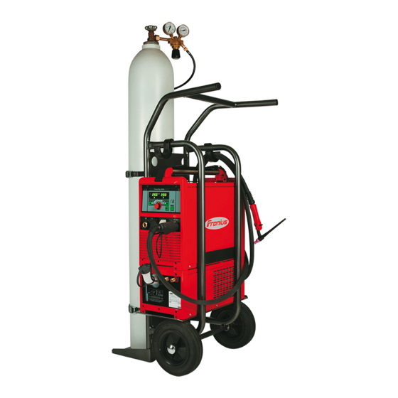
System components General The TransTig and MagicWave power sources can be used with a wide variety of system add-ons and options. Overview System add-ons and options Item Description Power sources Cooling units Trolley with gas cylinder holder Pedal remote control unit TIG welding torch Standard / Up/Down JobMaster TIG welding torch JobMaster TIG welding torch functions in conjunction with power sources:... -
Page 25: Control Elements And Connections
Control elements and connections... -
Page 27: Description Of The Control Panels
Description of the control panels General The key feature of the control panel is the logical way in which the control elements are arranged. All the main welding parameters needed for day-to-day working can easily be: selected using the buttons altered with the adjusting dial shown during welding on the digital display. -
Page 28: Overview
Overview "Description of the control panels" is composed of the following sections: MagicWave control panel TransTig control panel Key combinations - special functions MagicWave control panels: TransTig control panels: MW 1700 / 2200 TT 2200 MW 2500 / 3000 TT 2500 / 3000 MW 4000 / 5000 TT 4000 / 5000... -
Page 29: Magicwave Control Panel
MagicWave control panel MagicWave con- trol panel (15) (14) (13) (12) (11) (10) No. Function Left digital display HOLD indicator at the end of each welding operation, the actual values for the welding current and voltage are stored and the Hold indicator lights up. The Hold indicator refers to the last value reached by the main current I . - Page 30 No. Function Welding voltage indicator lights up when parameter I is selected. During welding the current actual value for the welding voltage is shown on the right-hand digital display. Before welding, the following appears on the right digital display: 0.0 if a TIG welding mode is selected 50 V if an MMA welding mode is selected (after a delay of 3 seconds;...
- Page 31 No. Function Gas-test button to set the required shielding gas flow rate on the pressure regulator After pressing this button, shielding gas flows for 30 seconds. Press the button again to stop the gas flow prematurely. (10) Welding parameters overview The welding parameters overview contains the most important welding parameters to be used when welding.
- Page 32 No. Function (12) Welding current indicator for indicating the welding current for the welding parameters Starting current I Welding current I Final current I Before welding commences, the left-hand digital display shows the set value. For and I , the right-hand digital display also shows the respective percentage of the welding current I After welding begins, the welding parameter I is automatically selected.
-
Page 33: Transtig Control Panel
TransTig control panel TransTig control panel (14) (13) (12) (11) (10) No. Function Left digital display HOLD indicator at the end of each welding operation, the actual values for the welding current and voltage are stored and the Hold indicator lights up. The Hold indicator refers to the last value reached by the main current I . - Page 34 No. Function Welding voltage indicator lights up when parameter I is selected. During welding the current actual value for the welding voltage is shown on the right-hand digital display. Before welding, the following appears on the right digital display: 0.0 if a TIG welding mode is selected 50 V if an MMA welding mode is selected (after a delay of 3 seconds;...
- Page 35 No. Function Welding parameters overview The welding parameters overview contains the most important welding parameters to be used when welding. The sequence of welding parameters follows a clothes- line structure. Use the left and right welding parameter selection buttons to navigate within the welding parameters overview.
- Page 36 No. Function (12) Left parameter selection button for selecting welding parameters within the welding parameters overview (9) When a welding parameter is selected, the LED on the relevant parameter symbol lights up. (13) HF (high frequency) ignition indicator lights up when the HFt setup parameter has been set to an interval for the high fre- quency pulses (14) Overtemperature indicator lights up if the power source overheats (e.g.
-
Page 37: Key Combinations - Special Functions
Key combinations - special functions General The following functions can be called up by pressing buttons simultaneously or repeatedly on the MagicWave and TransTig control panels. Displaying the Display software version: software version, while pressing and holding the Mode button, press the left parameter operating time selection button. -
Page 38: Connections, Switches And Mechanical Components
Connections, switches and mechanical components MagicWave 1700 / 2200 MagicWave 1700 / 2200 - front MagicWave 1700 / 2200 - rear No. Function Welding torch connection for connecting: the TIG welding torch the electrode cable for manual metal arc welding LocalNet connection standardised connection socket for system add-ons (e.g. -
Page 39: Magicwave2500 / 3000
MagicWave 2500 / 3000 MagicWave 2500 / 3000 - front MagicWave 2500 / 3000 - rear No. Function Grounding (earthing) cable connection for connecting the grounding (earthing) cable LocalNet connection standardised connection socket for system add-ons (e.g. remote control, JobMas- ter TIG welding torch, etc.) Handle Torch control connection... -
Page 40: Magicwave4000 / 5000
MagicWave 4000 / 5000 (5) (4) (3) MagicWave 4000 / 5000 - front MagicWave 4000 / 5000 - rear No. Function Mains switch for switching the power source on and off Welding torch connection for connecting the TIG welding torch Electrode holder connection for connecting the electrode cable for manual metal arc welding Torch control connection... -
Page 41: Transtig 2200
TransTig 2200 TransTig 800 / 2200 - front TransTig 800 / 2200 - rear No. Function (+) current socket with bayonet latch for connecting the grounding (earthing) cable when TIG welding the electrode cable or grounding (earthing) cable during MMA welding (de-... -
Page 42: Transtig2500 / 3000
TransTig 2500 / 3000 TransTig 2500 / 3000 - front TransTig 2500 / 3000 - rear No. Function (+) current socket with bayonet latch for connecting the grounding (earthing) cable when TIG welding the electrode cable or grounding (earthing) cable during MMA welding (de- pending on the type of electrode) LocalNet connection standardised connection socket for system add-ons (e.g. -
Page 43: Transtig4000 / 5000
TransTig 4000 / 5000 TransTig 4000 / 5000 - front TransTig 4000 / 5000 - rear No. Function (+) current socket with bayonet latch for connecting the grounding (earthing) cable when TIG welding the electrode cable or grounding (earthing) cable during MMA welding (de- pending on the type of electrode) LocalNet connection standardised connection socket for system add-ons (e.g. -
Page 45: Installation And Commissioning
Installation and commissioning... -
Page 47: Minimum Equipment Needed For Welding Task
Minimum equipment needed for welding task General Depending on which welding process you intend to use, a certain minimum equipment lev- el will be needed in order to work with the power source. The welding processes and the minimum equipment levels required for the welding task are then described. -
Page 48: Before Installation And Commissioning
Before installation and commissioning Safety WARNING! Danger due to incorrect operation and incorrectly performed work. This can result in severe personal injury and damage to property. ► All the work and functions described in this document must only be carried out and used by trained and qualified personnel. -
Page 49: Generator-Powered Operation (Mw 1700 / 2200, Tt2200)
CAUTION! An inadequately dimensioned electrical installation can cause serious damage. ► The mains lead and its fuse must be dimensioned to suit the local power supply. The technical data shown on the rating plate applies. Generator-pow- The MW 1700/2200 and TT 2200 power sources are generator-compatible, provided that ered operation the maximum apparent power delivered by the generator is at least 10 kVA. -
Page 50: Connecting Up The Mains Cable On Us Power Sources
Connecting up the mains cable on US power sourc- General The US power sources are supplied without a mains cable. A mains cable appropriate for the connection voltage must be fitted prior to commissioning. A strain-relief device for a cable cross-section AWG 10 is installed on the power source. Strain-relief devices for larger cable cross-sections must be designed accordingly. -
Page 51: Replacing The Strain-Relief Device
Undo the screws (2 x) and clamping nut (size 30) on the strain-relief device Insert the mains cable into the strain- relief device NOTE! Push the mains cable in far enough to make it possible to connect the ground conductor and the phase conductors to the block terminal properly. - Page 52 Insert the hexagon nut (size 50 mm) into the holding plate NOTE! To ensure a reliable earth connection to the housing of the power source, the points on the hexagon nut must be fa- cing the holding plate. Screw the front of the large strain-relief device into the hexagon nut (size 50 mm).
-
Page 53: Start-Up
Start-up Safety WARNING! An electric shock can be fatal. If the device is plugged into the mains during installation, there is a high risk of very serious injury and damage. ► Only carry out work on the device if the mains switch is in the "O" position. ►... -
Page 54: Establishing A Ground (Earth) Connection To The Workpiece
Take the protective cap off the gas cylinder Briefly open the gas cylinder valve to remove any dust or dirt Check the seal on the pressure regulator Screw the pressure regulator onto the gas cylinder and tighten it When using a TIG welding torch with an integral gas connector: Use the gas hose to connect the pressure regulator to the shielding gas connection on the rear of the power source Tighten the union nut on the gas hose... -
Page 55: Welding
Welding... -
Page 57: Tig Modes
TIG modes Safety WARNING! Danger from incorrect operation. Possible serious injury and damage to property. ► Do not use the functions described here until you have read and completely under- stood these Operating Instructions. ► Do not use the functions described here until you have fully read and understood all of the Operating Instructions for the system components, in particular the safety rules! See the "The Setup menu"... -
Page 58: 2-Step Mode
Main current phase (welding-current Reduced current phase: intermediate low- phase): uniform thermal input into the ering of the welding current in order to pre- base material, whose temperature is vent any local overheating of the base raised by the advancing heat material Gas post-flow time at maximum welding Gas post-flow time at minimum welding... -
Page 60: 4-Step Mode
4-step mode Welding start-up with starting current I : Pull back and hold the torch trigger Welding with main current I : Release the torch trigger Lowering to final current I : Pull back and hold the torch trigger End of welding: Release the torch trigger down 4-step mode Intermediate lowering... -
Page 62: Special 4-Step Mode: Variant 4
Special 4-step Variant 4 of the special 4-step mode is activated when the SFS set-up parameter is set to mode: "4". variant 4 Welding start-up and welding: briefly pull back and release the torch trigger - the weld- ing current will rise at the specified upslope value from the starting current I until it reaches the main current value I Push forward and hold the torch trigger for intermediate lowering... -
Page 63: Cap Shaping And Cap Overloading
Cap shaping and cap overloading Cap-shaping On MagicWave power sources, an auto- matic cap-shaping function is available for the TIG AC welding process: When the TIG AC welding process is selected, activate automatic cap- shaping The ideal cap for the specified diame- ter of the tungsten electrode is formed during welding start-up. -
Page 64: Tig Welding
TIG welding Safety WARNING! Danger from incorrect operation. Possible serious injury and damage to property. ► Do not use the functions described here until you have read and completely under- stood these Operating Instructions. ► Do not use the functions described here until you have fully read and understood all of the Operating Instructions for the system components, in particular the safety rules! WARNING! An electric shock can be fatal. -
Page 65: Preparation
DownSlope t down Unit Setting range 0.0 - 9.9 Factory setting The DownSlope t is saved separately for 2-step and 4-step modes. down Final current I Unit % (of main current I Setting range 0 - 100 Factory setting Balance (only on MagicWave for TIG AC welding process) Unit Setting range -5 to +5... - Page 66 AC welding process AC welding process with automatic cap-shaping function DC welding process Use the left or right parameter selection button to select the relevant welding param- eters in the welding parameters overview Use the adjusting dial to set the selected welding parameter to the required value All welding parameter set values that have been set using the adjusting dial remain stored until the next time they are changed.
-
Page 67: Igniting The Arc
Risk of injury due to shock caused by electric shock (HF ignition) Although Fronius devices comply with all relevant standards, high-frequency ignition can transmit a harmless but noticeable electric shock under certain circumstances. ► Use prescribed protective clothing, especially gloves! ►... -
Page 68: Touchdown Ignition
Increase the tilt angle of the torch and actuate the torch trigger according to the mode you have selected The arc ignites without the electrode touching down on the workpiece. Tilt the torch back into the normal posi- tion Carry out welding Touchdown igni- If the HFt setup parameter is set to OFF, HF ignition is deactivated. -
Page 69: End Of Welding
Actuate the torch trigger Shielding gas flows. Gradually tilt the welding torch up until the tungsten electrode touches the workpiece Raise the welding torch and move it into its normal position The arc ignites. Carry out welding End of welding Depending on the set mode, finish welding by releasing the torch trigger Wait for the set gas post-flow and hold welding torch in position over the end of the weld seam... -
Page 70: Special Functions And Options
Special functions and options Arc break watch- If the arc breaks and the current does not start to flow again within the time specified in the dog function set-up menu, the power source cuts out automatically. The service code "no | Arc" appears on the control panel. - Page 71 IMPORTANT The following points apply to the pulsed welding current: The power source automatically regulates the pulsing parameters as a function of the pre- set main current I The pulsed welding current begins: after the end of the starting-current phase I with the upslope phase UPS Depending on what tAC time has been set, the pulsed welding current may continue up to and including the final current phase I...
-
Page 72: Mma Welding
MMA welding Safety WARNING! Danger from incorrect operation. Possible serious injury and damage to property. ► Do not use the functions described here until you have read and completely under- stood these Operating Instructions. ► Do not use the functions described here until you have fully read and understood all of the Operating Instructions for the system components, in particular the safety rules! WARNING! An electric shock can be fatal. -
Page 73: Hotstart Function
NOTE! If the MMA welding mode is selected, the welding voltage will only be available after a 3-second delay. Only for MagicWave: press the process button to select the required welding process: MMA AC welding process MMA DC- welding process MMA DC+ welding process NOTE! The TransTig power source has no switchover facility between the MMA DC- and... -
Page 74: Anti-Stick Function
Legend I (A) Hot-current time, 0-2 s, factory setting: 0.5 s HotStart current, 0-200%, factory setting 150% Main current = set welding current Function: during the specified hot-current time (Hti), the welding current I is increased to the HotStart current HCU. t (s) To activate the hotstart function, the Hot- Start current HCU must be >... -
Page 75: Setup Settings
Setup settings... -
Page 77: The Setup Menu
The Setup menu General The set-up menu provides easy access to the knowledge base in the power source and to additional functions. The set-up menu can be used to make simple adjustments of the welding parameters to suit the various job settings. The following can be found in the set-up menu: Set-up parameters that have an immediate effect on the welding process Set-up parameters needed for making the preliminary settings on the welding system... -
Page 78: Shielding Gas Setup Menu
Shielding gas setup menu General The Protective gas shield set-up menu provides easy access to the protective gas shield settings. Opening the Pro- Press and hold the "Mode" button tective gas shield set-up menu Press the Gas test button The power source is now in the Protective gas shield set-up menu. The last welding parameter selected is displayed. - Page 79 Factory setting The value set for G-H only applies if the maximum welding current actually has been set. The actual value is derived from the present welding current. For a medium welding cur- rent, for example, the actual value will be half of the value set for G-H. IMPORTANT! The values set for the G-L and G-H set-up parameters are added together.
-
Page 80: Tig Setup Menu
TIG setup menu Opening the TIG Press the Mode button to select 2-step mode or 4-step mode set-up menu Press and hold the "Mode" button Press the right parameter selection button The power source is now in the TIG set-up menu. The last welding param- eter selected is displayed. - Page 81 In this case, welding starts with touchdown ignition. CAUTION! Risk of injury due to shock caused by electric shock Although Fronius devices comply with all relevant standards, high-frequency ignition can transmit a harmless but noticeable electric shock under certain circumstances. ► Use prescribed protective clothing, especially gloves! ►...
- Page 82 Pre Ignition - delayed ignition with immediate high frequency start Unit Setting range OFF / 0.1 - 1 Factory setting If a time value is set for the parameter Pri, the welding arc is ignited with a delay corre- sponding to this value: Press the torch trigger - high frequency is activated for the speci- fied duration - the welding arc is ignited Reduced current - Intermediate lowering of the welding current in order to prevent any local overheating of the base material (4-step mode).
-
Page 83: Rod Electrode Setup Menu
Rod electrode setup menu Open the rod Press the Mode button to select the MMA welding mode electrode set-up menu Press and hold the "Mode" button Press the right parameter selection button The power source is now in the rod electrode set-up menu. The last weld- ing parameter selected is displayed. - Page 84 dYn - arc force dynamic correction Unit Setting range 0 - 100 Factory setting soft, low-spatter arc harder, more stable arc To obtain optimum welding results, it will sometimes be necessary to adjust the arc-force dynamic. Functional principle: at the instant of droplet transfer or when a short circuit occurs, there is a momentary rise in amperage.
-
Page 85: Rod Electrode Setup Menu: Level 2
Rod electrode setup menu: level 2 Opening the rod Open the rod electrode set-up menu electrode set-up Select "2nd" welding parameter menu level 2 Press and hold the "Mode" button Press the right parameter selection button The power source is now in the rod electrode set-up menu - level 2. The last welding parameter selected is displayed. - Page 86 Load line for rod electrode Load line for rod electrode where arc length is in- con - 20 A / V U (V) creased Load line for rod electrode where arc length is re- duced Characteristic where "CON" parameter is select- ed (constant welding current) Characteristic where "0.1 - 20"...
- Page 87 Load line for rod electrode Load line for rod electrode where arc length is in- creased U (V) Load line for rod electrode where arc length is re- duced Characteristic where "CON" parameter is select- ed (constant welding current) Characteristic where "0.1 - 20" parameter is se- lected (drooping characteristic with adjustable slope) Characteristic where "P"...
-
Page 89: Troubleshooting And Maintenance
Troubleshooting and maintenance... -
Page 91: Troubleshooting
Troubleshooting General The digital power sources are equipped with an intelligent safety system. This means that apart from the fuse for the coolant pump, it has been possible to dispense with fuses en- tirely. After a possible malfunction or error has been remedied, the power source can be put back into normal operation again without any fuses having to be replaced. - Page 92 tP2 | xxx Note: xxx stands for a temperature value Cause: Overtemperature in the primary circuit of the power source Remedy: Allow power source to cool down tP3 | xxx Note: xxx stands for a temperature value Cause: Overtemperature in the primary circuit of the power source Remedy: Allow power source to cool down tP4 | xxx...
- Page 93 Err | 051 Cause: Mains undervoltage: The mains voltage has dropped below the lower limit of the tolerance range (see section "Technical data") Remedy: Check the mains voltage Err | 052 Cause: Mains overvoltage: The mains voltage has exceeded the upper limit of the tol- erance range (see section "Technical data") Remedy: Check the mains voltage...
-
Page 94: Power Source - Troubleshooting
no | H2O Cause: Cooling unit flow watchdog has been triggered Remedy: Check the cooling unit; if necessary, top up the coolant or bleed the system as described in "Putting the cooling unit into service" hot | H2O Cause: Thermostat on cooling unit has tripped Remedy: Wait until the end of the cooling phase, i.e. - Page 95 Nothing happens when the torch trigger is pressed Mains switch is on, indicators are lit up Cause: The control plug is not plugged in Remedy: Plug in the control plug Cause: Welding torch or welding torch control line is faulty Remedy: Replace welding torch No protective gas shield...
-
Page 96: Care, Maintenance And Disposal
Care, maintenance and disposal General Under normal operating conditions, the power source requires only a minimum of care and maintenance. However, it is vital to observe some important points to ensure it remains in a usable condition for many years. Safety WARNING! Work that is carried out incorrectly may result in serious injury or damage to prop-... -
Page 97: Every 6 Months
Every 6 months CAUTION! Danger due to the effect of compressed air. This can result in damage to property. ► Do not bring the air nozzle too close to electronic components. Dismantle device side panels and clean inside of device with dry, reduced com- pressed air If a lot of dust has accumulated, clean the cooling air ducts WARNING! -
Page 99: Appendix
Appendix... -
Page 101: Technical Data
Technical data Special voltages CAUTION! An inadequately dimensioned electrical installation can cause serious damage. ► The mains lead and its fuse must be dimensioned accordingly. The technical data shown on the rating plate applies. MagicWave MW 1700 MW 2200 1700 / 2200 Mains voltage 230 V 230 V... -
Page 102: Magicwave2500 / 3000
MagicWave MW 2500 MW 3000 2500 / 3000 Mains voltage 3 x 400 V 3 x 400 V Mains voltage tolerance ± 15 % ± 15 % Mains frequency 50/60 Hz 50/60 Hz Mains fuse protection (slow-blow) 16 A 16 A Mains connection at PCC at PCC... -
Page 103: Magicwave4000 / 5000
MW 2500 MV MW 3000 MV Primary continuous power (100% d.c. 3 x 400 - 460 V 4.8 kVA 5.1 kVA 3 x 200 - 240 V 4.4 kVA 4.9 kVA 1 x 200 - 240 V 3.9 kVA 4.3 kVA Cos phi 0,99 0,99... -
Page 104: Magicwave 4000 / 5000 Mv
MW 4000 MW 5000 Mains fuse protection (slow-blow) 35 A 35 A Mains connection Restrictions possible Restrictions possible Primary continuous power (100% d.c. 15.5 kVA 17.9 kVA Cos phi 0,99 0,99 Welding current range 3 - 400 A 3 - 500 A Electrode 10 - 400 A 10 - 440 A... -
Page 105: Transtig 800 / 2200
MW 4000 MV MW 5000 MV Welding current at 10 min/40 °C (104 °F) 40% d.c. 500 A 10 min/40 °C (104 °F) 45% d.c. 400 A 10 min/40 °C (104 °F) 60% d.c. 360 A 440 A 10 min/40 °C (104 °F) 100% d.c. 300 A 350 A Open circuit voltage... -
Page 106: Transtig2500 / 3000
Striking voltage (U 9.0 kV 9.5 kV The arc striking voltage is suitable for manual operation. Degree of protection IP 23 IP 23 Type of cooling Insulation class EMC device class (in accordance with EN/IEC 60974-10) Dimensions L x W x H (with handle) 485/180/344 mm 485/180/390 mm 19.1/7.1/13.5 in. -
Page 107: Transtig 2500 / 3000 Mv
TT 2500 TT 3000 Weight 24.2 kg 24.2 kg 53.35 lb. 53.35 lb. Mark of conformity S, CE S, CE TransTig TT 2500 MV TT 3000 MV 2500 / 3000 MV Mains voltage 3 x 200 - 240 V 3 x 200 - 240 V 3 x 400 - 460 V 3 x 400 - 460 V 1 x 200 - 240 V... -
Page 108: Transtig4000 / 5000
TT 2500 MV TT 3000 MV Degree of protection IP 23 IP 23 Type of cooling Insulation class EMC emission class (in accordance with EN/IEC 60974-10) Dimensions L x W x H (with handle) 560 / 250 / 435 mm 560 / 250 / 435 mm 22.0 / 9.8 / 17.1 in. -
Page 109: Transtig 4000 / 5000 Mv
TransTig TT 4000 MV TT 5000 MV 4000 / 5000 MV Mains voltage 3 x 200 - 240 V 3 x 200 - 240 V 3 x 380 - 460 V 3 x 380 - 460 V Mains voltage tolerance ±... -
Page 110: Terms And Abbreviations Used
Terms and abbreviations used General The terms and abbreviations listed here are used in connection with functions that are ei- ther included in the standard scope of supply or that are available as optional extras. Terms and abbre- viations A - F AC frequency Cooling unit control dynamic... -
Page 111: Terms And Abbreviations I - U
Terms and abbre- viations I - U Reduced current (4-step mode with intermediate lowering) Phase Adjustment Phase adjustment of the mains connection of two power sources for simultaneous AC welding Pre Ignition - delayed high frequency ignition Tacking function UpSlope The starting current is continuously increased until it reaches the welding current... - Page 112 FRONIUS INTERNATIONAL GMBH Froniusstraße 1, A-4643 Pettenbach, Austria E-Mail: sales@fronius.com www.fronius.com Under www.fronius.com/contact you will find the addresses of all Fronius Sales & Service Partners and locations...
Need help?
Do you have a question about the TransTig 2200 and is the answer not in the manual?
Questions and answers