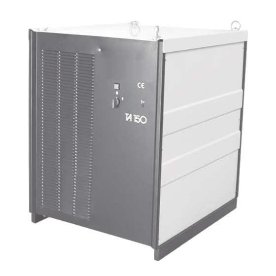
Summary of Contents for Fronius TransArc 150 Leybold
- Page 1 Bedienungsanleitung Ersatzteillisten Plasma-Stromquelle Operating Instructions TransArc 150 Leybold Spare Parts List Plasma power source 42,0410,0326 011998...
-
Page 3: Table Of Contents
Haftung. Für Instandhaltungs- und Überholungsarbeiten verwenden Sie Always use only original FRONIUS spare parts for maintenance nur Original- FRONIUS Ersatzteile. Unser Kundendienst, welcher and overhaul work. Our after-sales service department - with its über fachmännisch geschultes Personal, geeignete Mittel und highly trained staff and specialist resources and facilities - will be Einrichtungen verfügt, steht Ihnen selbstverständlich gerne zur... -
Page 4: Beschreibung Der Bedienungselemente
BESCHREIBUNG DER BEDIENUNGSELEMENTE Netzleuchte Über-Unterspannungs-LED Diese Leuchtdiode leuchtet, wenn die Netzspannung außerhalb des Bereiches von +/- 10 % liegt Netzhauptschalter Abb. 1... -
Page 5: Inbetriebnahme Allgemein
INBETRIEBNAHME ALLGEMEIN Die Stromquelle ist serienmäßig für eine Netzspannung von 3x400V / 50Hz ausgelegt. Bei Sonderspannungen (z.B. 500V) muß ein Fronius-Vorschalttrafo verwendet werden. Die Pha- senfolge ist beim Anschluß nicht zu beachten. Achtung! Montage des Netzsteckers sowie andere elektri- sche Eingriffe dürfen nur von einem ELEKTRO-FACHMANN durchgeführt werden. -
Page 6: Technische Daten
TECHNISCHE DATEN READY Diese drei potentialfreien Kontakte schließen nach dem Netzspannung 3x400 V / 50-60 Hz (+/- 10%) Einschalten des Gerätes (etwa 2 Sekunden anzugverzö- 51 A Max. Stromaufnahme gert). Folgende Bedingungen müssen dabei erfüllt werden: Absicherung 63 A 1. Hauptschalter in Stellung "1" Schutzart IP 21 2. -
Page 7: Einstellanleitung Pli3
4. KONTROLLE DER LEISTUNGSTEILE 1. Gerät ca. 10 min. warmlaufen lassen Die Leistungsteile werden im spannungsfreien Zustand ge- 2. OFFSETEINSTELLUNG messen. Meßgerät am TP 63 / GND -> RTR Print anschließen und mit Achtung! Ca. 5 min. warten bis Netzelkos entladen sind. dem mit Offset bezeichneten Einstellregler am HP4 0V +/-3mV Dazu schaltet man das Meßgerät auf Diodenmeßbereich einstellen. -
Page 8: Änderung Der Netzspannung Auf 380 / 415V
Anlauframpe Zeit: 3 Jumper Bezeichnung AZ0 - AZ2 0,25 s 0,5 s 0,75 s 1,0 s 1,25 s 1,5 s 1,75 s Anlauframpe Spannung: 3 Jumper Bezeichnung AS0 - AS2 7,5 V 15,0 V 22,5 V 30 V 37,5 V 45 V 52,5 V 60 V... -
Page 9: Operating Instructions
OPERATING INSTRUCTIONS... -
Page 11: Description Of Operating Elements
DESCRIPTION OF OPERATING ELEMENTS Mains indicator Over-undervoltage-LED This LED lights up when the mains - voltage is out of a range from +/- 10 Mains switch Fig. 1... -
Page 12: Commissioning - General Details
The standard power source is designed for a mains voltage of 3x400V / 50Hz. For unusual voltages (for example 500V) a Fronius ancillary autotransformer must be used. There is no need to take the phase sequence into account when wiring... -
Page 13: Technical Data
PLASMA TECHNICAL DATA This signal is generated by a make-contact which closes Mains voltage 3x400 V / 50-60 Hz (+/- 10%) when the plasmacurrent flows. Max. current consumption 51 A Relay contact datas: 24V/500mA Fuse protection 63 A READY Protection class IP 21 This 3 potential-free contacts are closing if the mains supply is present ->... -
Page 14: Adjusting Manual Pli3
4. CHECK OF POWER MODULES 3. GAIN ADJUSTMENT The power modules will be measured in dead condition. Specify a command value of 75A and set 0.75 V on the TP63 Attention! Wait 5 minutes after switching off (-RTR) with the P1 PLI3 board. Now adjust the output current Set your measurements to diode check range and check to 75A (as measured with the current measuring rod), using the on the primary rectifiers V1 and V21. -
Page 15: Changing Of Mains Voltage Range To 380 / 415V
Start-up ramp time: 3 jumpers Designation AZ0 - AZ2 0.25 s 0.5 s 0.75 s 1.0 s 1.25 s 1.5 s 1.75 s Start-up ramp voltage: 3 jumpers Designation AS0 - AS2 7.5 V 15.0 V 22.5 V 30 V 37.5 V 45 V 52.5 V... -
Page 17: Ersatzteilliste
Ersatzteilliste Spare Parts List Liste de pièces de rechange Lista parti di ricambio Lista de repuestos Lista de peças sobresselentes Onderdelenlijst Reservdelsliste Seznam náhradních dílů Ñïèñîê çàïàñíûõ ÷àñòåé ud_fr_st_tb_00150 012002... - Page 18 61-63,65 10,11 56-57 27 20 22 23 68,69 42-45 28 24 26 25 34,39 59,60 19,21 TA 150 PLASMA 4,075,043,590 Ersatzteilliste / Spare parts list / Listes de pièces de rechange / Lista de repuestos / Lista de pecas sobresselentes / Lista dei Ricambi el_fr_st_pl_00169 012000...
- Page 19 POS. BENENNUNG ARTICLE DENOMINATION DRUCK VORDERFR. TA150 PL. FRONT PANEL TA150 PL. BE PANNEAU FRONTAL TA150 PL. 46.0750.0457 SEITENT.L/R.GR TA150 PLASMA SIDE PANEL L/R.GR TA150 PLASMA PANNEAU LATERAL TA150 PL BE BB2.0200.5019 DECKEL GR TA150 PLASMA LEYBOLD COVER GR.TA150 PLASMA LEYBOLD COUVERCLE TA150 PLASMA LEYBOLD BB2.0200.5017 LEUCHTDIODE 1.5...
- Page 20 POS. BENENNUNG ARTICLE DENOMINATION WIDVAR 1K3 10 VARISTOR 1K3 10 385 VARISTANCE 1K3 10 385 41.0001.0602 RINGMUTTER 582 M 12 VZ LIFTING EYE M12 DIN 582 ETRIER PORTEUR 42.0400.0097 NETZFILTER 63A MAINS-INTERFERENCE TA150 CABLE INTERFERENCES TA150 43.0001.1024 FUNKENTSTÖRDROSSEL 10MM² INTERFERENCE SUPPRESSION 10MM² INTERFERENCE SUPPRESIONE 43.0010.0207 TRANSI 450 500 44 TO227 SC...
- Page 21 FRONIUS INTERNATIONAL GMBH Buxbaumstraße 2, A-4600 Wels, Austria Tel: +43 (0)7242 241-0, Fax: +43 (0)7242 241-3940 E-Mail: sales@fronius.com www.fronius.com www.fronius.com/addresses Under http://www.fronius.com/addresses you will find all addresses of our Sales & service partners and Locations. ud_fr_st_so_00082 012008...


Need help?
Do you have a question about the TransArc 150 Leybold and is the answer not in the manual?
Questions and answers