Table of Contents
Advertisement
Quick Links
/ Perfect Charging / Perfect Welding / Solar Energy
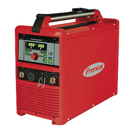
TransTig 2200 / 2500 Comfort
TransTig 3000 / 4000 Comfort
TransTig 5000 Comfort
MagicWave 2200 / 2500 Comfort
MagicWave 3000 / 4000 Comfort
MagicWave 5000 Comfort
42,0426,0063,EN 022-18122020
Fronius prints on elemental chlorine free paper (ECF) sourced from certified sustainable forests (FSC).
Operating instructions
TIG power source
Advertisement
Table of Contents
Troubleshooting

Related Manuals for Fronius TransTig 5000 Comfort


Summary of Contents for Fronius TransTig 5000 Comfort
- Page 1 TransTig 3000 / 4000 Comfort TIG power source TransTig 5000 Comfort MagicWave 2200 / 2500 Comfort MagicWave 3000 / 4000 Comfort MagicWave 5000 Comfort 42,0426,0063,EN 022-18122020 Fronius prints on elemental chlorine free paper (ECF) sourced from certified sustainable forests (FSC).
-
Page 3: Table Of Contents
Contents Safety rules Explanation of safety notices General Proper use Environmental conditions Obligations of the operator Obligations of personnel Mains connection Protecting yourself and others Noise emission values Danger from toxic gases and vapours Danger from flying sparks Risks from mains current and welding current Meandering welding currents EMC Device Classifications EMC measures... - Page 4 Automated TIG welding MMA welding Before installation and commissioning Safety Utilisation for intended purpose Setup regulations Mains connection Start-up Safety Remarks on the cooling unit General Connecting the gas cylinder Establishing a ground (earth) connection to the workpiece Connecting the welding torch Welding TIG modes Safety...
- Page 5 Welding job Finishing the welding job Saving settings as a job General Preparation Saving settings as a job Finish saving job Setup settings The Setup menu General Overview TIG setup Opening the TIG setup Changing welding parameters Exiting TIG setup Welding parameters in the TIG setup TIG setup 2nd Opening the TIG setup 2nd...
- Page 6 AC setup (for rod electrodes) General Opening the AC setup Changing welding parameters Exiting AC setup Welding parameters in AC setup General Opening the Job set-up menu Save / retrieve Overview Optimising a job Optimising a job Renaming a job Finish optimising job Adjustable TIG parameters Adjustable rod electrode parameters...
- Page 7 MagicWave 5000 Comfort MagicWave 5000 Comfort MV TransTig2200 Comfort TransTig 2500 Comfort TransTig 3000 Comfort TransTig 2500 Comfort MV TransTig 3000 Comfort MV TransTig 4000 Comfort TransTig 4000 Comfort MV TransTig 5000 Comfort TransTig 5000 Comfort MV Explanation of footnotes...
-
Page 8: Safety Rules
Safety rules Explanation of DANGER! safety notices Indicates immediate danger. ▶ If not avoided, death or serious injury will result. WARNING! Indicates a potentially hazardous situation. ▶ If not avoided, death or serious injury may result. CAUTION! Indicates a situation where damage or injury could occur. ▶... -
Page 9: Environmental Conditions
The device is intended solely for the welding processes specified on the rating plate. Any use above and beyond this purpose is deemed improper. The manufacturer shall not be held liable for any damage arising from such usage. Proper use includes: carefully reading and following all the instructions given in the operating instructions studying and obeying all safety and danger notices carefully performing all stipulated inspection and maintenance work. -
Page 10: Protecting Yourself And Others
This may affect a number device types in terms of: Connection restrictions Criteria with regard to the maximum permissible mains impedance Criteria with regard to the minimum short-circuit power requirement at the interface with the public grid see "Technical data" In this case, the plant operator or the person using the device should check whether the device may be connected, where appropriate by discussing the matter with the power supply company. -
Page 11: Danger From Toxic Gases And Vapours
Danger from The fumes produced during welding contain harmful gases and vapours. toxic gases and Welding fumes contain substances that cause cancer, as stated in Monograph 118 of the vapours International Agency for Research on Cancer. Use at-source extraction and a room extraction system. If necessary, use a welding torch with an integrated extraction device. -
Page 12: Risks From Mains Current And Welding Current
Risks from mains An electric shock is potentially life threatening and can be fatal. current and weld- Do not touch live parts either inside or outside the device. ing current During MIG/MAG welding and TIG welding, the welding wire, the wirespool, the feed rollers and all pieces of metal that are in contact with the welding wire are live. -
Page 13: Meandering Welding Currents
Meandering weld- If the following instructions are ignored, meandering welding currents can develop with ing currents the following consequences: Fire hazard Overheating of parts connected to the workpiece Irreparable damage to ground conductors Damage to device and other electrical equipment Ensure that the workpiece is held securely by the workpiece clamp. -
Page 14: Emf Measures
Shielding, if necessary Shield off other nearby devices Shield off entire welding installation EMF measures Electromagnetic fields may pose as yet unknown risks to health: effects on the health of others in the vicinity, e.g. wearers of pacemakers and hear- ing aids wearers of pacemakers must seek advice from their doctor before approaching the device or any welding that is in progress... -
Page 15: Requirement For The Shielding Gas
Hook chains and/or ropes onto all suspension points provided on the load-carrying equipment. Chains and ropes must be at the smallest angle possible to the vertical. Remove gas cylinder and wire-feed unit (MIG/MAG and TIG devices). If the wire-feed unit is attached to a crane holder during welding, always use a suitable, insulated wirefeeder hoisting attachment (MIG/MAG and TIG devices). -
Page 16: Danger From Escaping Shielding Gas
The manufacturer's instructions must be observed as well as applicable national and international regulations for shielding gas cylinders and accessories. Danger from Risk of suffocation from the uncontrolled escape of shielding gas escaping shield- Shielding gas is colourless and odourless and, in the event of a leak, can displace the ing gas oxygen in the ambient air. -
Page 17: Commissioning, Maintenance And Repair
Before switching on the device, ensure that no one is likely to be endangered. Check the device at least once a week for obvious damage and proper functioning of safety devices. Always fasten the shielding gas cylinder securely and remove it beforehand if the device is to be transported by crane. -
Page 18: Disposal
(e.g. relevant product standards of the EN 60 974 series). Fronius International GmbH hereby declares that the device is compliant with Directive 2014/53/EU. The full text on the EU Declaration of Conformity can be found at the follow- ing address: http://www.fronius.com... -
Page 19: General Information
General information... -
Page 21: General
General Device concept The MagicWave (MW) 2200 / 2500 / 3000 / 4000 / 5000 Comfort and TransTig (TT) 2200 / 2500 / 3000 / 4000 / 5000 Comfort TIG power sources are com- pletely digitised, microprocessor-controlled inverter power sources. Their modular design and potential for sys- tem add-ons ensure a high degree of flex- ibility. -
Page 22: System Components
System components General The TransTig and MagicWave power sources can be used with a wide variety of system add-ons and options. Overview (10) (11) System add-ons and options Item Description TIG robot welding torch Cold wire feeders with wire drive Power sources Cooling units Trolley with gas cylinder holder... -
Page 23: Control Elements And Connections
Control elements and connections... -
Page 25: Description Of The Control Panels
Description of the control panels General NOTE! Due to software updates, you may find that your device has certain functions that are not described in these operating instructions or vice versa. Individual illustrations may also differ slightly from the actual controls on your device, but these controls function in exactly the same way. - Page 26 Function Tacking indicator lights up when the tAC set-up parameter has been set to a period of time Electrode overload indicator lights up if the tungsten electrode is overloaded See section on TIG welding in Chapter "Welding mode" for more informa- tion on the electrode overload indicator.
-
Page 27: Transtig Comfort Control Panel
Function (15) HF (high frequency) ignition indicator lights up when the HF ignition welding parameter has been set to an inter- val for the high frequency pulses TransTig Comfort control panel (14) (13) (12) (11) (10) Function Pulse indicator lights up when the F-P set-up parameter has been set to a pulse frequency Spot welding indicator lights up when the SPt set-up parameter has been set to a spot welding time... - Page 28 Function When a mode is selected, the LED on the relevant symbol lights up. (10) Gas test button for setting the required shielding gas flow rate on the gas pressure regulator After pressing this button, gas flows for 30 seconds. Press the button again to stop the gas flow prematurely.
-
Page 29: Connections, Switches And Mechanical Components
Connections, switches and mechanical compon- ents MagicWave 2200 Comfort MagicWave 2200 Comfort - front MagicWave 2200 Comfort - rear Function Welding torch connection for connecting: the TIG welding torch the electrode cable for manual metal arc welding LocalNet connection standardised connection socket for system add-ons (e.g. remote control, Job- Master TIG welding torch, etc.) Handle Torch control connection... -
Page 30: Magicwave2500 / 3000 Comfort
MagicWave 2500 / 3000 Com- fort MagicWave 2500 / 3000 Comfort - front MagicWave 2500 / 3000 Comfort - rear Function Grounding (earthing) cable connection for connecting the grounding (earthing) cable LocalNet connection standardised connection socket for system add-ons (e.g. remote control, Job- Master TIG welding torch, etc.) Handle Torch control connection... -
Page 31: Magicwave4000 / 5000 Comfort
MagicWave 4000 / 5000 Com- fort MagicWave 4000 MagicWave 4000 / 5000 Comfort - front MagicWave 4000 / 5000 Comfort - rear Function Mains switch to switch the power source on and off Welding torch connection for connecting the TIG welding torch Electrode holder connection for connecting the electrode cable for manual metal arc welding Torch control connection... -
Page 32: Transtig2200 Comfort
TransTig 2200 Comfort TransTig 2200 Comfort - front TransTig 2200 Comfort - rear Function (+) current socket with bayonet latch for connecting the grounding (earthing) cable when TIG welding the electrode cable or grounding (earthing) cable during MMA welding (depending on the type of electrode) LocalNet connection standardised connection socket for system add-ons (e.g. -
Page 33: Transtig2500 / 3000 Comfort
TransTig 2500 / 3000 Com- fort TransTig 2500 / 3000 Comfort - front TransTig 2500 / 3000 Comfort - rear Function (+) current socket with bayonet latch for connecting the grounding (earthing) cable when TIG welding the electrode cable or grounding (earthing) cable during MMA welding (depending on electrode type) LocalNet connection standardised connection socket for system add-ons (e.g. -
Page 34: Transtig4000 / 5000 Comfort
TransTig 4000 / 5000 Com- fort TransTig 4000 TransTig 4000 / 5000 Comfort - front TransTig 4000 / 5000 Comfort - rear Function (+) current socket with bayonet latch for connecting the grounding cable when TIG welding the electrode cable or grounding cable during MMA welding (depending on the type of electrode) LocalNet connection standardised connection socket for system add-ons (e.g. -
Page 35: Installation And Commissioning
Installation and commissioning... -
Page 37: Minimum Equipment Needed For Welding Task
Minimum equipment needed for welding task General Depending on which welding process you intend to use, a certain minimum equipment level will be needed in order to work with the power source. The welding processes and the minimum equipment levels required for the welding task are then described. -
Page 38: Before Installation And Commissioning
Before installation and commissioning Safety WARNING! Danger due to incorrect operation and incorrectly performed work. This can result in severe personal injury and damage to property. ▶ All the work and functions described in this document must only be carried out and used by trained and qualified personnel. - Page 39 CAUTION! An inadequately dimensioned electrical installation can cause serious damage. ▶ The mains lead and its fuse must be dimensioned to suit the local power supply. The technical data shown on the rating plate applies.
-
Page 40: Start-Up
Start-up Safety WARNING! An electric shock can be fatal. If the device is plugged into the mains during installation, there is a high risk of very seri- ous injury and damage. ▶ Only carry out work on the device if the mains switch is in the "O" position. ▶... -
Page 41: Establishing A Ground (Earth) Connection To The Workpiece
Secure the gas cylinder Take the protective cap off the gas cylinder Briefly open the gas cylinder valve to remove any dust or dirt Check the seal on the pressure regulator Screw the pressure regulator onto the gas cylinder and tighten it When using a TIG welding torch with an integral gas connector: Use the gas hose to connect the pressure regulator to the shielding gas connection on the rear of the power source... -
Page 43: Welding
Welding... -
Page 45: Tig Modes
TIG modes Safety WARNING! Danger from incorrect operation. Possible serious injury and damage to property. ▶ Do not use the functions described here until you have read and completely under- stood these Operating Instructions. ▶ Do not use the functions described here until you have fully read and understood all of the Operating Instructions for the system components, in particular the safety rules! See the "The Setup menu"... -
Page 46: 2-Step Mode
2-step mode Welding: Pull back and hold the torch trigger End of welding: Release the torch trigger NOTE! To work in 2-step mode after it has been selected, the SPt setup parameter must be set to "OFF" and the spot welding indicator on the control panel must not light G-L / G-H down 2-step mode... -
Page 47: 4-Step Mode
down Spot welding 4-step mode Start of welding with starting current I : Pull back and hold the torch trigger Welding with main current I : Release the torch trigger Lowering to final current I : Pull back and hold the torch trigger End of welding: Release the torch trigger NOTE! For 4-step mode, the special 4‑step (SFS) setup parameter must be set to "OFF". -
Page 48: Special 4-Step Mode: Variant
Briefly pull back the torch trigger to start intermediate lowering to the specified reduced current I . Briefly pull back the torch trigger a second time, to restore the main current I down Special 4-step mode: Variant 1 Special 4-step Variant 2 of the special 4-step mode is activated when the special 4-step SFS set-up mode: parameter ‑is set to "2“. - Page 49 When the torch trigger is pulled back, welding ends immediately without downslope and final current. G-L / G-H Special 4-step mode: Variant 3 Special 4-step Variant 4 of the special 4-step mode is activated when the SFS set-up parameter is set to mode: "4".
-
Page 50: Cap Shaping And Cap Overloading
Cap shaping and cap overloading Cap-shaping On MagicWave power sources, an automatic cap-shaping function is available for the TIG AC welding pro- cess: When the TIG AC welding process is selected, activate automatic cap-shaping The ideal cap for the specified dia- meter of the tungsten electrode is formed during welding start-up. -
Page 51: Tig Welding
TIG welding Safety WARNING! Danger from incorrect operation. Possible serious injury and damage to property. ▶ Do not use the functions described here until you have read and completely under- stood these Operating Instructions. ▶ Do not use the functions described here until you have fully read and understood all of the Operating Instructions for the system components, in particular the safety rules! WARNING! - Page 52 UpSlope, 2-step mode UpSlope, 4-step mode Unit Setting range 0.0 - 9.9 Factory setting IMPORTANT! The UpSlope is saved separately for 2-step and 4-step modes. Main current, 2-step mode Main current, 4-step mode Unit Setting range MW 2200 Comfort 3-220 TT 2200 Comfort 3 - 220 MW 2500 Comfort 3-250 TT 2500 Comfort 3 - 250...
- Page 53 DownSlope, 2-step mode DownSlope, 4-step mode Unit Setting range 0.0 - 9.9 Factory setting IMPORTANT! The DownSlope is saved separately for 2-step and 4-step modes. Final current, 2-step mode Final current, 4-step mode Unit % (of main current) Setting range 0 - 100 Factory setting only with MagicWave for the TIG AC welding process...
-
Page 54: Preparation
Ensure that the tungsten electrode does not touch any persons or electrically con- ductive or earthed parts (e.g. housing, etc.). Move the mains switch to the "I" position The starting sequence with the Fronius logo, current firmware version and Fronius internet address is displayed for approx. 1 second: TIG welding... - Page 55 Only with MagicWave: Press the Mode button to select the required TIG mode: AC welding process AC welding process with automatic cap-shaping function DC welding process Use the right arrow key to select the relevant welding parameters Use the adjusting dial to set the selected welding parameter to the required value If necessary, additional welding parameters can be set in the Setup menu: Press the Menu key The relevant menu is displayed:...
-
Page 56: Igniting The Arc
Risk of injury due to shock caused by electric shock (HF ignition) Although Fronius devices comply with all relevant standards, high-frequency ignition can transmit a harmless but noticeable electric shock under certain circumstances. ▶ Use prescribed protective clothing, especially gloves! ▶... -
Page 57: Touchdown Ignition
Increase the tilt angle of the torch and actuate the torch trigger according to the mode you have selected The arc ignites without the electrode touching down on the workpiece. Tilt the torch back into the normal pos- ition Carry out welding Touchdown igni- If the HFt setup parameter is set to OFF, HF ignition is deactivated. -
Page 58: End Of Welding
Actuate the torch trigger Shielding gas flows. Gradually tilt the welding torch up until the tungsten electrode touches the workpiece Raise the welding torch and move it into its normal position The arc ignites. Carry out welding End of welding Depending on the set mode, finish welding by releasing the torch trigger Wait for the set gas post-flow and hold welding torch in position over the end of the weld seam... -
Page 59: Special Functions And Options
Special functions and options Arc break watch- If the arc breaks and the current does not start to flow again within the time specified in dog function the set-up menu, the power source cuts out automatically. The service code "no | Arc" appears on the control panel. -
Page 60: Tacking Function
Mode of operation of TIG pulsing when TIG DC welding is selected: 1/F-P down TIG pulsing - welding current curve Legend: Starting current Pulse frequency *) Final current Duty cycle Upslope Ground current Downslope Main current Down *) (1/F-P = time interval between two pulses) Tacking function The tacking function is available for the TIG DC welding process. -
Page 61: Tig Cold-Wire Welding
Legend: Duration of pulsed welding current for the tacking process Starting current Final current UpSlope DownSlope Down Main current NOTE! The following points apply to the pulsed welding current: ▶ The power source automatically regulates the pulsing parameters as a function of the specified main current I ▶... - Page 62 1/F-P down Legend: Starting current Duty cycle Final current Ground current Upslope Main current Downslope Pulse frequency Down Fd.1 Wire feed speed 1 Fd.2 Wire feed speed 2 Delay in the start of wirefeeding Delay in the end of wirefeeding from the beginning of main cur- from the end of main current rent phase I...
-
Page 63: Mma Welding
MMA welding Safety WARNING! Danger from incorrect operation. Possible serious injury and damage to property. ▶ Do not use the functions described here until you have read and completely under- stood these Operating Instructions. ▶ Do not use the functions described here until you have fully read and understood all of the Operating Instructions for the system components, in particular the safety rules! WARNING! -
Page 64: Welding Parameters For Rod Electrodes
Welding paramet- ers for rod elec- trodes Starting current: starting current < main current ("Soft- Starting current: starting current = main current Start") Starting current: starting current > main current ("Hot- Start") Unit % (of main current) Setting range 0 - 200 Factory setting Main current: starting current <... -
Page 65: Preparation
To obtain optimum welding results, it will sometimes be necessary to adjust the arc- force dynamic. Unit % (of main current) Setting range 0 - 100 Factory setting soft, low-spatter arc harder, more stable arc Functional principle: at the instant of droplet transfer or in the event of a short circuit, there is a momentary rise in amperage. -
Page 66: Mma Welding
Make sure that the rod electrode does not touch any persons or electrically conduct- ive or earthed parts (e.g. the housing, etc.). Move the mains switch to the "I" position The starting sequence with the Fronius logo, current firmware version and Fronius internet address is displayed for approx. 1 second: MMA welding... - Page 67 (e.g. the housing, etc.) Move the mains switch to the "I" position The starting sequence with the Fronius logo, current firmware version and Fronius internet address is displayed for approx. 1 second: Use the right arrow key to select the relevant welding parameters...
-
Page 68: Hotstart Function
Hotstart function To obtain optimum welding results, it will sometimes be necessary to adjust the hotstart function. Benefits Improved ignition, even when using electrodes with poor ignition properties Better fusion of the base material in the start-up phase, meaning fewer cold-shut defects Largely prevents slag inclusions For details on setting the available welding parameters, please refer to the "Rod elect. - Page 69 Electrode burn-out is prevented by activating the anti-stick function. If the rod electrode begins to stick, the power source immediately switches the welding current off. After the rod electrode has been detached from the workpiece, the welding process can be contin- ued without any problems.
-
Page 70: Welding Job
Welding job Safety WARNING! Danger from incorrect operation. Possible serious injury and damage to property. ▶ Do not use the functions described here until you have read and completely under- stood these Operating Instructions. ▶ Do not use the functions described here until you have fully read and understood all of the Operating Instructions for the system components, in particular the safety rules! WARNING! - Page 71 UpSlope, 2-step mode UpSlope, 4-step mode Unit Setting range 0.0 - 9.9 Factory setting IMPORTANT! The UpSlope is saved separately for 2-step and 4-step modes. Main current, 2-step mode Main current, 4-step mode Unit Setting range MW 2200 Comfort 3-220 TT 2200 Comfort 3 - 220 MW 2500 Comfort 3-250 TT 2500 Comfort 3 - 250...
- Page 72 DownSlope, 2-step mode DownSlope, 4-step mode Unit Setting range 0.0 - 9.9 Factory setting IMPORTANT! The DownSlope is saved separately for 2-step and 4-step modes. Final current, 2-step mode Final current, 4-step mode Unit % (of main current) Setting range 0 - 100 Factory setting only with MagicWave for the TIG AC welding process...
-
Page 73: Welding Parameters For Rod Electrodes
Unit Setting range OFF - max. OFF - max. Factory setting Welding paramet- ers for rod elec- trodes Starting current: starting current < main current ("Soft- Starting current: starting current = main current Start") Starting current: starting current > main current ("Hot- Start") Unit % (of main current) - Page 74 Main current: starting current < main current ("Soft- Main current: starting current = main current Start") Main current: starting current > main current ("HotStart") Unit Setting range MW 2200 Comfort 10 - 180 TT 2200 Comfort 10 - 180 MW 2500 Comfort 10 - 250 TT 2500 Comfort 10 - 250 MW 3000 Comfort 10 - 300 TT 3000 Comfort 10 - 300...
-
Page 75: Preparation
Ensure that the tungsten electrode does not touch any persons or electrically con- ductive or earthed parts (e.g. housing, etc.). Move the mains switch to the "I" position The starting sequence with the Fronius logo, current firmware version and Fronius internet address is displayed for approx. 1 second:... -
Page 76: Welding Job
Welding job Press Menu key The relevant main menu appears, e.g.: Use the adjusting dial to select "job" (turn the adjusting dial) Press the adjusting dial The menu items for the job will now appear: Use the adjusting dial to select 'Retrieve' (turn the adjusting dial) - Page 77 Press the adjusting dial The display now shows the last job that was selected: A free memory location is indicated as follows: Use the adjusting dial to select the desired job (turn the adjusting dial) To change welding parameters according to the job correction stored in the job: Use left and right arrow keys to select welding parameters Press the adjusting dial...
-
Page 78: Finishing The Welding Job
Press the adjusting dial The adjusted value of the selected welding parameter is applied Start welding Finishing the Finish welding welding job Press Menu key The main menu for the welding job appears: Use the adjusting dial to select "job" (turn the adjusting dial) Press the adjusting dial The menu items for an active job will now appear: Use the adjusting dial to select "Finish"... - Page 79 Press the adjusting dial The welding parameters are shown for the most recently selected method, e.g.: Starting current 2-step mode...
-
Page 80: Saving Settings As A Job
Saving settings as a job General In the individual welding processes, settings and welding parameters can be stored in 100 jobs (job numbers 0 to 99). Preparation Select the mode to be saved using the Mode button: TIG 2-step mode TIG 4-step mode Manual metal arc welding mode The relevant image for the welding parameters is displayed, e.g.:... -
Page 81: Saving Settings As A Job
Use the adjusting dial to select a welding parameter To change a welding parameter press the adjusting dial Change the welding parameter value using the adjusting dial Press the adjusting dial Press Menu key The latest menu appears, e.g.: Saving settings NOTE! as a job When settings are saved as a job, all the settings are stored in the welding para-... - Page 82 Press the adjusting dial The first "Save job" screen will appear: Turn the adjusting dial to select the job number under which the settings are to be stored Press the adjusting dial If there is memory available, then the settings will be stored under the selected job number.
- Page 83 Then press the adjusting dial in order to enter these letters / numbers: In order to delete letters / numbers, turn the adjusting dial and select 'Del': Press the adjusting dial to delete the last character: Press the button on the right (OK) in order to accept the name The settings will be stored and the third 'Save job' screen will appear:...
- Page 84 Press the button on the right (OK) The job numbers overview appears: Allocated memory: A warning prompt will appear: Press the button on the left or right: Left button (No): Do not overwrite job, return to job numbers overview Right button (Yes): Store settings under the chosen job number: The "Name job"...
- Page 85 Turn the adjusting dial to select the desired letters / numbers: Then press the adjusting dial in order to enter these letters / numbers: Press the button on the right (OK) in order to accept the name The settings will be stored and the "Job saved" screen will appear: Press the button on the right (OK) The job numbers overview appears:...
-
Page 86: Finish Saving Job
Finish saving job Press Menu key Select the arrow symbol by turning the adjusting dial Press the adjusting dial The menu items for the job will now appear: Press Menu key Select the arrow symbol by turning the adjusting dial Press the adjusting dial The current set-up menu is displayed:... - Page 87 Press Menu key Select the arrow symbol by turning the adjusting dial The current welding parameters are displayed e.g.: TIG welding parameters for 2-step mode (main current welding parameter selected)
-
Page 89: Setup Settings
Setup settings... -
Page 91: The Setup Menu
The Setup menu General The set-up menu provides easy access to the knowledge base in the power source and to additional functions. The set-up menu can be used to make simple adjustments of the welding parameters to suit the various job settings. The set-up menu contains all the set-up parameters that have an immediate effect on the welding process. -
Page 92: Tig Setup
TIG setup Opening the TIG Press the Mode button to select 2-step mode or 4-step mode setup The image for the TIG welding parameter is shown on the display: TIG welding parameters for 2-step mode TIG welding parameters for 4-step mode Press Menu key The main menu appears: Use the adjusting dial to select "TIG setup"... -
Page 93: Changing Welding Parameters
Changing weld- Select the desired welding parameter by turning the adjusting dial: ing parameters To set the welding parameter, press the adjusting dial The value of the selected welding parameter can now be changed: Change the welding parameter value by turning the adjusting dial: To apply the welding parameter value press the adjusting dial... -
Page 94: Exiting Tig Setup
Exiting TIG setup Press Menu key Select the arrow symbol by turning the adjusting dial Press the adjusting dial The main menu appears: Press Menu key Select the arrow symbol by turning the adjusting dial Press the adjusting dial The image for the TIG welding parameter is shown:... -
Page 95: Welding Parameters In The Tig Setup
TIG welding parameters for 2-step mode TIG welding parameters for 4-step mode Welding paramet- "Minimum" and "maximum" are used for setting ranges that differ according to power ers in the TIG source, wire-feed unit, welding program, etc. setup Spot welding time Unit Setting range OFF / 0.05 - 25.0... - Page 96 Pulse frequency Unit Hz / kHz Setting range OFF / 0.20 Hz - 2.00 kHz Factory setting The selected pulse frequency is also used for the reduced current I IMPORTANT!If the pulse frequency is set to "OFF": then the welding parameters Duty Cycle, Ground Current and Wirefeed spd2 (from cold wire setup) are not available the wire feed speed set on the control panel is used for constant wirefeed at a constant welding current.
- Page 97 down 2-step mode: Starting and final current time Legend: Main current Downslope Gas pre-flow time down Starting current Final current Starting current time Final current time UpSlope TIG-Setup 2nd Second level of the TIG setup...
-
Page 98: Tig Setup 2Nd
TIG setup 2nd Opening the TIG Opening the TIG setup setup 2nd Select the 'TIG setup 2nd' parameter Press the adjusting dial The TIG setup 2nd parameters are shown: The power source is now in TIG setup 2nd Changing weld- Select the desired welding parameter by turning the adjusting dial: ing parameters To set the welding parameter, press the adjusting dial... -
Page 99: Exiting Tig Setup 2Nd
Change the welding parameter value by turning the adjusting dial: To apply the welding parameter value press the adjusting dial Exiting TIG setup Press Menu key Select the arrow symbol by turning the adjusting dial Press the adjusting dial The TIG setup parameters are shown:... - Page 100 Press Menu key Select the arrow symbol by turning the adjusting dial Press the adjusting dial The main menu appears: Press Menu key Select the arrow symbol by turning the adjusting dial Press the adjusting dial The image for the TIG welding parameter is shown:...
-
Page 101: Welding Parameters In The Tig Setup 2Nd
TIG welding parameters for 2-step mode TIG welding parameters for 4-step mode Welding paramet- "Minimum" and "maximum" are used for setting ranges that differ according to power ers in the TIG source, wirefeeder, welding program, etc. setup 2nd Spec. 4-step Special 4-step mode Unit Setting range... - Page 102 In this case, welding starts with touchdown ignition. CAUTION! Risk of injury due to shock caused by electric shock Although Fronius devices comply with all relevant standards, high-frequency ignition can transmit a harmless but noticeable electric shock under certain circumstances. ▶...
- Page 103 L/R alignment L (inductivity) - welding circuit inductivity (in microhenry) R (resistance) - welding circuit resistance (in mOhm) See the "L/R alignment" section for further details. Ignition time-out Time until safety cut-out is triggered after abortive ignition attempt Unit Setting range 0.1 - 9.9 Factory setting IMPORTANT! "Ignition Time-Out"...
- Page 104 Special 2-step Special 2-step mode for HF ignition after touching the workpiece Unit Setting range OFF / 1 Factory setting Ignition sequence, when the STS parameter is set to 1: Touch the workpiece with the tungsten electrode The short circuit detection on the power source is triggered Lift the tungsten electrode off After 300 ms the gas pre-flow time begins HF ignition is initiated...
-
Page 105: Ac Setup
AC setup General This setup is only available with MagicWave power sources. Open the AC Press the Mode button to select 2-step mode or 4-step mode setup The image for the TIG welding parameter is shown on the display: TIG welding parameters for 2-step mode TIG welding parameters for 4-step mode Press Menu key The main menu appears:... -
Page 106: Changing Welding Parameters
Press the adjusting dial The AC setup parameters are shown: The power source is now in AC setup. Changing weld- Select the desired welding parameter by turning the adjusting dial: ing parameters To set the welding parameter, press the adjusting dial The value of the selected welding parameter can now be changed: Change the welding parameter value by turning the adjusting dial: To apply the welding parameter value press the adjusting dial... -
Page 107: Exiting Ac Setup
Exiting AC setup Press Menu key Select the arrow symbol by turning the adjusting dial Press the adjusting dial The main menu appears: Press Menu key Select the arrow symbol by turning the adjusting dial Press the adjusting dial The image for the TIG welding parameter is shown:... -
Page 108: Welding Parameters In Ac Setup
TIG welding parameters for 2-step mode TIG welding parameters for 4-step mode Welding paramet- "Minimum" and "maximum" are used for setting ranges that differ according to power ers in AC setup source, wire-feed unit, welding program, etc. AC frequency Unit Setting range Syn / 40 - 250 Factory setting... - Page 109 Balance I (A) AC frequency AC current offset t (s) Factory setting: 20% shift to the negative I (A) t (s) 60 Hz 120 Hz I (A) t (s) +70% -70% Effect of the AC parameters on the waveshape...
-
Page 110: Ac Setup 2Nd
AC setup 2nd General This setup is only available with MagicWave power sources. Opening the AC Open the AC setup setup 2nd Select the 'AC setup 2nd' parameter Press the adjusting dial The AC setup 2nd parameters are shown: The power source is now in AC setup 2nd. Changing weld- Select the desired welding parameter by turning the adjusting dial: ing parameters... - Page 111 To set the welding parameter, press the adjusting dial The value of the selected welding parameter can now be changed: Change the welding parameter value by turning the adjusting dial: To apply the welding parameter value press the adjusting dial...
-
Page 112: Exiting Ac Setup 2Nd
Exiting AC setup Press Menu key Select the arrow symbol by turning the adjusting dial Press the adjusting dial The AC setup parameters are shown: Press Menu key Select the arrow symbol by turning the adjusting dial Press the adjusting dial The main menu appears:... -
Page 113: Welding Parameters In Ac Setup 2Nd
Press Menu key Select the arrow symbol by turning the adjusting dial Press the adjusting dial The image for the TIG welding parameter is shown: TIG welding parameters for 2-step mode TIG welding parameters for 4-step mode Welding paramet- "Minimum" and "maximum" are used for setting ranges that differ according to power ers in AC setup source, wire-feed unit, welding program, etc. - Page 114 Neg. half-wave Negative half-wave Unit Setting range Tri / Sin / Rec / Off Factory setting Triangular waveform Sine ... sinusoidal waveform (standard setting for a low-noise, stable arc) Rectangular waveform with decreased edge steepness, for reducing noise levels compared to those that occur with the 100% rectangular waveform 100% rectangular waveform (stable but loud arc) Phase sync.
-
Page 115: Gas Setup
Gas setup General The gas setup offers easy access to the protective gas shield settings. Opening the gas Press the Mode button to select 2-step mode or 4-step mode setup The image for the TIG welding parameter is shown on the display: TIG welding parameters for 2-step mode TIG welding parameters for 4-step mode Press Menu key... -
Page 116: Changing Welding Parameters
Press the adjusting dial The gas setup parameters are shown: The power source is now in gas setup. Changing weld- Select the desired welding parameter by turning the adjusting dial: ing parameters To set the welding parameter, press the adjusting dial The value of the selected welding parameter can now be changed: Change the welding parameter value by turning the adjusting dial: To apply the welding parameter value press the adjusting dial... -
Page 117: Exiting Gas Setup
Exiting gas setup Press Menu key Select the arrow symbol by turning the adjusting dial Press the adjusting dial The main menu appears: Press Menu key Select the arrow symbol by turning the adjusting dial Press the adjusting dial The image for the TIG welding parameter is shown:... -
Page 118: Gas Setup Parameters
TIG welding parameters for 2-step mode TIG welding parameters for 4-step mode Gas setup para- "Minimum" and "maximum" are used for setting ranges that differ according to power meters source, wire-feed unit, welding program, etc. Pre-flow Gas pre-flow time Unit Setting range 0,0 - 9,9 Factory setting... - Page 119 IMPORTANT! The values set for the 'post-flow lmin' and 'post-flow lmax' welding para- meters are added together. For example, if both welding parameters are at maximum (25 s / 40 s), the gas post-flow will last: 25 s at minimum welding current 65 s at maximum welding current 37.5 s if the welding current is exactly half the maximum, etc.
- Page 120 Gas flushing Purging of protective gas shield Unit Setting range OFF / 0.1 - 10.0 Factory setting Purging of the protective gas shield begins as soon as "gas flushing" is allocated a value. For safety reasons, purging of the shielding gas cannot be restarted until a new gas flushing value is entered.
-
Page 121: Cold Wire Setup
Cold wire setup General The cold wire setup is only available if a cold wire feeder is connected to the power source. Opening the AC Press the Mode button to select 2-step mode or 4-step mode setup The image for the TIG welding parameter is shown on the display: TIG welding parameters for 2-step mode TIG welding parameters for 4-step mode Press Menu key... -
Page 122: Changing Welding Parameters
Press the adjusting dial The cold wire setup welding parameters are shown: The power source is now in the cold wire setup. Changing weld- Select the desired welding parameter by turning the adjusting dial: ing parameters To set the welding parameter, press the adjusting dial The value of the selected welding parameter can now be changed: Change the welding parameter value by turning the adjusting dial: To apply the welding parameter value press the adjusting dial... -
Page 123: Exiting The Cold Wire Setup
Exiting the cold Press Menu key wire setup Select the arrow symbol by turning the adjusting dial Press the adjusting dial The main menu appears: Press Menu key Select the arrow symbol by turning the adjusting dial Press the adjusting dial The image for the TIG welding parameter is shown:... -
Page 124: Welding Parameters In The Cold Wire Setup
TIG welding parameters for 2-step mode TIG welding parameters for 4-step mode Welding paramet- "Minimum" and "maximum" are used for setting ranges that differ according to power ers in the cold source, cold wire-feed unit, welding program, etc. wire setup Wirefeed spd2 Wire feed speed 2 Unit... - Page 125 Wire wdraw Unit Setting range OFF / 1 - 50 OFF / 0.04 - 1.97 Factory setting IMPORTANT!Wire withdrawal prevents the welding wire from burning at the end. Before the welding current is switched off, the wire is withdrawn to the set value. A pre- requisite for this function is that the arc has ignited.
-
Page 126: Calibrating Push-Pull Unit
Calibrating push-pull unit General The push-pull unit must be calibrated before it is started up for the first time and whenever the wire feed software is updated. If the push-pull unit is not calibrated, stand- ard welding parameters will be used - which may lead to an unsatisfactory welding result. Calibrating the For an overview of the service codes used during calibration of the push-pull unit, please push-pull unit... - Page 127 Use the adjusting dial to select the corresponding push-pull unit: Press the right arrow key The third push-pull calibration screen is shown: Follow the instructions shown CAUTION! Risk of injury from rotating cogs and drive parts. ▶ Keep hands away from rotating cogs and the wire drive parts. Press the right arrow key The fourth push-pull calibration screen is shown: Follow the instructions shown...
-
Page 128: General
30 m/min or 1181 ipm Fronius VR 1530 KD Fronius Robacta KD Drive 10 m/min or 394 ipm Fronius Robacta Plasma KD Drive Fronius Robacta Laser KD Drive Fronius Robacta KD Drive 22 m/min or 866 ipm Fronius Robacta Plasma KD Drive... -
Page 129: Service Codes During Calibration Of The Push-Pull Unit
Service codes The following abbreviations are used for the service codes shown during calibration of during calibration the push-pull unit: of the push-pull = Cold wire-feed unit unit = Push-pull unit vDmin = minimum wire feed speed vDma = maximum wire feed speed Service codes when the drive units are disengaged (open-circuit calibration) Cause: Incorrect measurement during... - Page 130 Cause: At maximum wire feed speed, the motor of the push-pull unit does not deliver any actual rota- tional speed value. Remedy: Repeat the push-pull calibra- tion. If the error message re- appears: Contact After-Sales Service. Cause: Push-pull calibration was inter- rupted: Quick-stop was activ- ated by pressing the torch trig- ger.
- Page 131 Cause: At minimum wire feed speed, the motor current of the wire- feed unit motor is outside the permitted range. Possible reas- ons are disengaged wire-feed unit motors or wire feed prob- lems. Remedy: Engage the drive units of both wirefeeder motors, arrange the hosepack in as straight a line as possible;...
- Page 132 Cause: At maximum wire feed speed, the motor current of the wire- feed unit motor is outside the permitted range. Possible reas- ons are disengaged wire-feed unit motors or wire feed prob- lems. Remedy: Engage the drive units of both wire-feed unit motors, arrange the hosep- ack in as straight a line as possible;...
-
Page 133: Rod Elec. Setup (Rod Electrode Setup)
Rod elec. setup (rod electrode setup) Open the rod Press the Mode button to select the MMA welding mode electrode setup The image for the rod electrode welding parameter is shown on the display, e.g.: Press Menu key The main menu appears: Use the adjusting dial to select "Rod elec. -
Page 134: Changing Welding Parameters
Changing weld- Select the desired welding parameter by turning the adjusting dial: ing parameters To set the welding parameter, press the adjusting dial The value of the selected welding parameter can now be changed: Change the welding parameter value by turning the adjusting dial: To apply the welding parameter value press the adjusting dial... -
Page 135: Exiting Rod Electrode-Setup
Exiting rod elec- Press Menu key trode-setup Select the arrow symbol by turning the adjusting dial Press the adjusting dial The main menu appears: Press Menu key Select the arrow symbol by turning the adjusting dial Press the adjusting dial The image for the rod electrode welding parameter is shown: Rod electrode "Minimum"... - Page 136 HotStart time Unit Setting range 0 - 2,0 Factory setting To obtain optimum welding results, it will sometimes be necessary to adjust the hot- start function. Advantages: Improved ignition, even when using electrodes with poor ignition properties Better fusion of the base material in the start-up phase, meaning fewer cold-shut defects Largely prevents slag inclusions Rod elec.
-
Page 137: Rod Elec. Setup 2Nd (Rod Electrode Setup 2Nd)
Rod elec. setup 2nd (rod electrode setup 2nd) Opening the rod Open the rod electrode setup electrode setup Select the 'rod electrode setup 2nd' parameter Press the adjusting dial The parameters for rod electrode setup 2nd are shown: The power source is now in rod electrode setup 2nd Changing weld- Select the desired welding parameter by turning the adjusting dial: ing parameters... -
Page 138: Exiting Rod Electrode Setup 2Nd
Change the welding parameter value by turning the adjusting dial: To apply the welding parameter value press the adjusting dial Exiting rod elec- Press Menu key trode setup 2nd Select the arrow symbol by turning the adjusting dial Press the adjusting dial The rod electrode setup parameters are shown:... - Page 139 Press Menu key Select the arrow symbol by turning the adjusting dial Press the adjusting dial The main menu appears: Press Menu key Select the arrow symbol by turning the adjusting dial Press the adjusting dial The image for the TIG welding parameter is shown:...
-
Page 140: Rod Electrode Setup 2Nd Welding Parameters
Rod electrode "Minimum" and "maximum" are used for setting ranges that differ according to power setup 2nd weld- source, wirefeeder, welding program, etc. ing parameters Anti-stick Unit Setting range ON / OFF Factory setting As the arc becomes shorter, the welding voltage may drop so far that the rod electrode will tend to stick. - Page 141 Parameter "0.1 - 20" (drooping characteristic with adjustable slope) Parameter "0.1 - 20" is used to set a drooping characteristic (5). The setting range extends from 0.1 A / V (very steep) to 20 A / V (very flat). Setting a flat characteristic (5) is only advisable for cellulose electrodes. NOTE! When setting a flat characteristic (5), set the arc-force dynamic to a higher value.
- Page 142 Where the welding current (I ) is permanently set, the operating point may migrate along the characteristics (4), (5) and (6) depending on the welding voltage at that moment in time. The welding voltage U is dependent upon the arc length. If the arc length changes, e.g.
-
Page 143: Ac Setup (For Rod Electrodes)
AC setup (for rod electrodes) General This setup is only available with MagicWave power sources. Opening the AC Press the Mode button to select the MMA welding mode setup The image for the rod electrode welding parameter is shown on the display, e.g.: Press Menu key The main menu appears:... -
Page 144: Changing Welding Parameters
Changing weld- Select the desired welding parameter by turning the adjusting dial: ing parameters To set the welding parameter, press the adjusting dial The value of the selected welding parameter can now be changed: Change the welding parameter value by turning the adjusting dial: To apply the welding parameter value press the adjusting dial... -
Page 145: Exiting Ac Setup
Exiting AC setup Press Menu key Select the arrow symbol by turning the adjusting dial Press the adjusting dial The main menu appears: Press Menu key Select the arrow symbol by turning the adjusting dial Press the adjusting dial The image for the rod electrode welding parameter is shown: Welding paramet- "Minimum"... - Page 146 AC frequency Unit Setting range Syn / 40 - 250 Factory setting for mains synchronisation of two power sources for simultan- eous AC welding.
-
Page 147: Job
General The following actions can be performed in the Job set-up menu: Save: Save settings as a job Retrieve: Retrieve jobs for the welding job Retrieve: Adjust and modify stored jobs Delete: Delete stored jobs Opening the Job Press Menu key set-up menu The main menu appears, e.g.: Use the adjusting dial to select "job"... -
Page 148: Overview
Overview The Job set-up menu comprises the following sections: Optimise job Delete a job... -
Page 149: Optimising A Job
Optimising a job Optimising a job Use the adjusting dial to select '"optimise" (turn the adjusting dial) Press the adjusting dial The first "Optimise job" screen or the last job to be selected or saved appears: Example job Press the adjusting dial to select the job The job to be optimised can now be selected:... - Page 150 Use the adjusting dial to select the number of the job to be optimised (turn the adjusting dial) Press the adjusting dial The welding parameters for the job to be optimised appear: Turn the adjusting dial to select the welding parameters to be modified, e.g.: Press the adjusting dial The value of the selected welding parameter can now be changed:...
-
Page 151: Renaming A Job
Change the welding parameter value by turning the adjusting dial: To apply the welding parameter value press the adjusting dial Renaming a job In the "Optimise job" menu item, turn the adjusting dial to select "Job name" Press the adjusting dial The "Name job"... - Page 152 If you press the adjusting dial the last character will be deleted: Turn the adjusting dial to select the desired letters / numbers: Then press the adjusting dial in order to enter these letters / numbers: Press the button on the right (OK) in order to accept the name The new job name is applied and the "Optimise job"...
-
Page 153: Finish Optimising Job
Finish optimising Press Menu key Select the arrow symbol by turning the adjusting dial Press the adjusting dial The menu items for the job appear: Press Menu key Select the arrow symbol by turning the adjusting dial Press the adjusting dial The current set-up menu is displayed:... -
Page 154: Adjustable Tig Parameters
Press Menu key Select the arrow symbol by turning the adjusting dial Press the adjusting dial The current welding parameters will appear, e.g.: TIG welding parameters for 2-step mode (main current welding parameter selected) Adjustable TIG Electrode diam. parameters Electrode diameter Unit Setting range Off / 0.1 - 4.8... - Page 155 DownSlope Unit Setting range 0.0 - 9.9 Final current Unit % (of main current) Setting range 0 - 100 Jobslope For changing to another job during welding. Jobslope is the time that it takes for the welding current to adjust seamlessly from the present job to the next. Unit Setting range Off / 0.1 - 9.9...
- Page 156 Legend: (1)..Gas post-flow time at any given moment (2)..Welding current at any given moment G-H..Post-flow Imax G-L ..Post-flow Imin Gas post-flow time as a function of the welding current If Aut is selected, the gas post-flow time is calculated automatically. This takes the selected welding process (AC or DC welding) into account.
- Page 157 Base current Unit % (of main current I Setting range 0 - 100 Polarity Unit Setting range AC (only MagicWave) / DC- / DC+ AC frequency only with MagicWave for the TIG AC welding process Unit Setting range Syn / 40 - 250 for mains synchronisation of two power sources for simultan- eous AC welding.
- Page 158 Final current time Unit Setting range OFF / 0.01 - 9.9 The final current time t-E specifies the duration of the final current phase I IMPORTANT! The final current time only applies in 2-step mode. In 4-step mode, the duration of the final current phase I is controlled with the torch trigger (see: "TIG oper- ating modes").
-
Page 159: Adjustable Rod Electrode Parameters
Wire withdrawal Unit Setting range OFF / 1 - 50 OFF / 0.04 - 1.97 IMPORTANT! Wire withdrawal prevents the welding wire from burning at the end of welding. Before the welding current is switched off, the wire is withdrawn by the set value. - Page 160 Starting current time Unit Setting range OFF / 0.01 - 9.9 The starting current time t-S specifies the duration of the starting-current phase I Char. To select characteristics Unit Setting range con or 0.1 - 20 or P Factory setting con - 20 A / V U (V) Load line for rod electrode...
- Page 161 NOTE! If there are problems with a rod electrode tending to "stick", set the arc-force dynamic to a higher value. Load line for rod electrode U (V) Load line for rod electrode where arc length is increased Load line for rod electrode where arc length is reduced Characteristic where "CON"...
- Page 162 Polarity Unit Setting range AC (only MagicWave) / DC- / DC+ AC frequency only with MagicWave for the TIG AC welding process Unit Setting range Syn / 40 - 250 for mains synchronisation of two power sources for simultan- eous AC welding. IMPORTANT! If using the "Syn"...
-
Page 163: Deleting A Job
Deleting a job Deleting a job Use the adjusting dial to select "Delete" (turn the adjusting dial) Press the adjusting dial The first "Delete job" screen is displayed: Turn the adjusting dial to select the job for deletion: Press the right button The second "Delete job"... - Page 164 The third "Delete job" screen is displayed: Press the right button The menu items for the job appear: Press Menu key Select the arrow symbol by turning the adjusting dial Press the adjusting dial The current set-up menu is displayed:...
- Page 165 Press Menu key Select the arrow symbol by turning the adjusting dial Press the adjusting dial The current welding parameters are displayed e.g.: TIG welding parameters for 2-step mode (main current welding parameter selected)
-
Page 166: Basic Setting
Basic setting General The basic settings can be called up in the menu when TIG 2-step mode, TIG 4-step mode or manual metal arc welding mode is selected. Opening the Press Menu key basic settings The main menu appears: TIG main menu Rod electrode main menu Use the adjusting dial to select "Basic setting"... -
Page 167: Changing Welding Parameters
Changing weld- Select the desired welding parameter by turning the adjusting dial: ing parameters To set the welding parameter, press the adjusting dial The value of the selected welding parameter can now be changed: Change the welding parameter value by turning the adjusting dial: To apply the welding parameter value press the adjusting dial... -
Page 168: Exiting Basic Settings
Exiting basic set- Press Menu key tings Select the arrow symbol by turning the adjusting dial Press the adjusting dial The relevant main menu appears: TIG main menu Rod electrode main menu Press Menu key Select the arrow symbol by turning the adjusting dial... -
Page 169: Basic Setting Parameters
Press the adjusting dial The image for the currently selected mode is shown, e.g.: TIG welding parameters for 2-step mode Basic setting "Minimum" and "maximum" are used for setting ranges that differ according to power parameters source, cold wire-feed unit, welding program, etc. Language Unit Setting range... -
Page 170: Info
Info General The info screen can be called up in the menu when TIG 2-step mode, TIG 4-step mode or rod electrode welding mode is selected. Calling up the Press Menu key info screen The main menu appears: TIG main menu Rod electrode main menu Use the adjusting dial to select "Info"... -
Page 171: Exiting The Info Screen
Exiting the info Press Menu key screen Select the arrow symbol by turning the adjusting dial Press the adjusting dial The relevant main menu appears: TIG main menu Rod electrode main menu Press Menu key Select the arrow symbol by turning the adjusting dial... -
Page 172: Entries On The Info Screen
Press the adjusting dial The image for the currently selected mode is shown, e.g.: TIG welding parameters for 2-step mode Entries on the Firmware info screen Current display/control panel firmware UST Software Current software of the power source control board UST Arc burn time Arc time Actual total arc burn time since using for the first time... -
Page 173: Lock Keys
Lock keys General To prevent welding parameters or settings from being changed either intentionally or unintentionally, the 'Lock keys' function can be activated on the power source. Lock keys Press Menu key The main menu appears: TIG main menu Rod electrode main menu Use the adjusting dial to select "Lock keys"... -
Page 174: Unlock Keys Again
Unlock keys Press Menu key again The 'Lock/unlock keys' screen appears: Press the key on the right (OK) within 3 seconds The keys are unlocked and the image for the currently selected mode is shown, e.g.: TIG welding parameters for 2-step mode (main current welding parameter selected) -
Page 175: Factory - For Resetting The Welding Machine
Factory - for resetting the welding machine General The welding machine can be reset in the menu when TIG 2‑step mode, TIG 4-step mode or rod electrode welding mode is selected. NOTE! When the welding machine is reset, all the personal settings in the set-up menu are lost. - Page 176 If you press the button on the right the basic settings will appear:...
-
Page 177: L/R Alignment
L/R alignment L = Welding circuit inductivity, mH (Microhenry) Abbreviations R = Welding circuit inductivity, mOhm (Milliohm) General informa- The way that the hosepack is arranged has a very significant effect on the weld proper- tion on welding ties. Particularly with pulsed-arc welding and AC welding, a high welding circuit inductiv- circuit inductivity ity may occur, depending on the length of the hosepack and on the way that it is arranged. - Page 178 Select "L/R align." by turning the adjusting dial: Press the adjusting dial The first L/R alignment screen is displayed: In the following L/R alignment screens, pressing the left button takes you back to the previous screen. Press the right arrow key The second L/R alignment screen is displayed: Follow the instructions shown IMPORTANT! Make sure that the contact between the earthing clamp and...
- Page 179 Press the right arrow key After R/L alignment, a confirmation and the current welding circuit resist- ance will be shown: Press the right arrow key Depending on the mode selected, TIG setup 2nd or rod electrode setup 2nd is displayed:...
-
Page 181: Troubleshooting And Maintenance
Troubleshooting and maintenance... -
Page 183: Troubleshooting
Troubleshooting General The digital power sources are equipped with an intelligent safety system. This means that apart from the fuse for the coolant pump, it has been possible to dispense with fuses entirely. After a possible malfunction or error has been remedied, the power source can be put back into normal operation again without any fuses having to be replaced. - Page 184 Cause: No preconfigured program has been selected Remedy: Select a configured program E2 - E4 Cause: Overtemperature in the second- ary circuit of the power source Remedy: Allow power source to cool down E5 - E10 Cause: Overtemperature in the primary circuit of the power source Remedy: Allow power source to cool...
- Page 185 When using power sources with a cold wire- feed unit Cause: Fault in cold wire-feed unit Remedy: Check cold wire-feed unit Cause: Overtemperature in the control circuit Remedy: Allow power source to cool down If the power source is being used with a robot interface or a field bus Cause: Robot not ready...
- Page 186 Cause: Mains undervoltage: The mains voltage has dropped below the lower limit of the tolerance range (see section "Technical data") Remedy: Check the mains voltage Cause: Mains overvoltage: The mains voltage has exceeded the upper limit of the tolerance range (see section "Technical data") Remedy: Check the mains voltage...
- Page 187 Cause: Arc break Remedy: Press the torch trigger repeatedly; clean the surface of the workpiece Cause: Secondary overvoltage: safety cut-out has tripped. Remedy: Contact After-Sales Service Cause: Overtemperature on TP 08 remote control Remedy: Allow TP 08 remote control to cool down Cause: Interface fault...
- Page 188 Cause: The upper current limit was exceeded Remedy: Check welding parameters Cause: The current dropped below the lower limit Remedy: Check welding parameters Cause: The upper voltage limit was exceeded Remedy: Check welding parameters Cause: The voltage dropped below the lower limit Remedy: Check welding parameters...
-
Page 189: Service Codes Displayed In Conjunction With The Digital Gas Control Option
Cause: Emergency Stop - safety circuit is open Remedy: Contact After-Sales Service Cause: The VRD (Voltage Reduction Device) function has interrupted the welding process Remedy: Contact After-Sales Service Service codes Cause: The gas watchdog option has displayed in con- detected that there is no gas junction with the pressure digital gas con-... -
Page 190: Power Source - Troubleshooting
Cause: The external supply voltage has dropped below the tolerance limit Remedy: Check the external supply voltage Cause: No actual speed value from the wire-feed unit motor Remedy: Check actual value and leads, if the error persists contact After- Sales Service Cause: No actual speed value from the wire-feed unit motor... - Page 191 No welding current Mains switch is on, indicators are lit up Cause: Grounding (earthing) connection is incorrect Remedy: Check the grounding (earthing) connection and terminal for correct polarity Cause: There is a break in the current cable in the welding torch Remedy: Replace welding torch Nothing happens when the torch trigger is pressed...
- Page 192 The welding torch becomes very hot Cause: The dimensions of the welding torch are inadequate Remedy: Observe the duty cycle and loading limits Cause: Only on water-cooled machines: water flow rate is insufficient Remedy: Check the water level, water flow rate, cleanliness, etc. If the coolant pump is blocked: use a screwdriver - placed on the bushing - to turn the coolant pump shaft Cause:...
-
Page 193: Care, Maintenance And Disposal
Care, maintenance and disposal General Under normal operating conditions, the power source requires only a minimum of care and maintenance. However, it is vital to observe some important points to ensure it remains in a usable condition for many years. Safety WARNING! Work that is carried out incorrectly may result in serious injury or damage to prop-... -
Page 194: Every 6 Months
Every 6 months CAUTION! Danger due to the effect of compressed air. This can result in damage to property. ▶ Do not bring the air nozzle too close to electronic components. Dismantle device side panels and clean inside of device with dry, reduced com- pressed air If a lot of dust has accumulated, clean the cooling air ducts WARNING! -
Page 195: Appendix
Appendix... -
Page 197: Average Consumption Values During Welding
Average consumption values during welding Average wire Average wire electrode consumption at a wire speed of 5 m/min electrode con- 1.0 mm wire 1.2 mm wire 1.6 mm wire sumption during electrode dia- electrode dia- electrode dia- MIG/MAG welding meter meter meter Steel wire electrode... -
Page 198: Technical Data
An overview of which critical raw materials are contained in this device can be found at materials, year of the following Internet address. production of the www.fronius.com/en/about-fronius/sustainability. device To calculate the year of production of the device: Each device is provided with a serial number... -
Page 199: Magicwave 2500 Comfort
Working voltage 10.1 - 18.8 V Electrode 20.4 - 27.2 V Striking voltage (U 9.5 kV The arc striking voltage is suitable for manual operation. Degree of protection IP 23 Type of cooling Insulation class EMC device class (in accordance with EN/IEC 60974-10) Dimensions L/W/H (with handle) 485 / 180 / 390 mm 19.1 / 7.1 / 15.4 in. -
Page 200: Magicwave 3000 Comfort
The arc striking voltage is suitable for manual operation. Degree of protection IP 23 Type of cooling Insulation class Dimensions L/W/H (with handle) 560 / 250 / 435 mm 22.0 / 9.8 / 17.1 in. Weight 26.6 kg 58.64 lb. Mark of conformity S, CE Idle state power consumption at 400 V... -
Page 201: Magicwave 2500 Comfort Mv
Mark of conformity S, CE Idle state power consumption at 400 V 50.0 W Power source efficiency at 300 A / 32.0 V MagicWave 2500 Mains voltage 3 x 200 - 240 V Comfort MV 3 x 400 - 460 V 1 x 200 - 240 V Mains voltage tolerance ±... -
Page 202: Magicwave 3000 Comfort Mv
Working voltage 10.1 - 20.0 V Electrode 20.4 - 30.0 V Striking voltage (U 10 kV The arc striking voltage is suitable for manual operation. Degree of protection IP 23 Type of cooling Insulation class EMC device class (in accordance with EN/IEC 60974-10) Dimensions L/W/H (with handle) 560 / 250 / 435 mm 22.0 / 9.8 / 17.1 in. -
Page 203: Magicwave 4000 Comfort
Welding current at 3 x 400 - 460 V 300 A 10 min/40 °C (104 °F) 35% D.C. 10 min/40 °C (104 °F) 40% D.C. 190 A 10 min/40 °C (104 °F) 100% D.C. Welding current at 3 x 200 - 240 V 300 A 10 min/40 °C (104 °F) 30% D.C. -
Page 204: Magicwave 4000 Comfort Mv
Welding current range 3 - 400 A Electrode 10 - 400 A Welding current at 10 min/40 °C (104 °F) 40% D.C. 400 A 10 min/40 °C (104 °F) 45% D.C. 365 A 10 min/40 °C (104 °F) 60% D.C. 310 A 10 min/40 °C (104 °F) 100% D.C. -
Page 205: Magicwave 5000 Comfort
Welding current at 10 min/40 °C (104 °F) 40% D.C. 400 A 10 min/40 °C (104 °F) 45% D.C. 360 A 10 min/40 °C (104 °F) 60% D.C. 300 A 10 min/40 °C (104 °F) 100% D.C. Open circuit voltage 90 V Working voltage 10.1 - 26.0 V... -
Page 206: Magicwave 5000 Comfort Mv
Welding current at 500 A 10 min/40 °C (104 °F) 40% D.C. 10 min/40 °C (104 °F) 45% D.C. 440 A 10 min/40 °C (104 °F) 60% D.C. 350 A 10 min/40 °C (104 °F) 100% D.C. Open circuit voltage 90 V Working voltage 10.1 - 30.0 V... -
Page 207: Transtig2200 Comfort
Welding current at 500 A 10 min/40 °C (104 °F) 40% D.C. 10 min/40 °C (104 °F) 45% D.C. 440 A 10 min/40 °C (104 °F) 60% D.C. 350 A 10 min/40 °C (104 °F) 100% D.C. Open circuit voltage 90 V Working voltage 10.1 - 30.0 V... -
Page 208: Transtig 2500 Comfort
Welding current at 220 A 10 min/25 °C (77 °F) 50% D.C. 200 A 10 min/25 °C (77 °F) 60% D.C. 170 A 10 min/25 °C (77 °F) 100% D.C. 220 A 10 min/40 °C (104 °F) 40% D.C. 180 A 10 min/40 °C (104 °F) 60% D.C. -
Page 209: Transtig 3000 Comfort
Welding current at 10 min/40 °C (104 °F) 45% D.C. 250 A 10 min/40 °C (104 °F) 50% D.C. 240 A 10 min/40 °C (104 °F) 60% D.C. 210 A 10 min/40 °C (104 °F) 100% D.C. Open circuit voltage 85 V Working voltage 10.1 - 20.0 V... -
Page 210: Transtig 2500 Comfort Mv
Working voltage 10.1 - 22.0 V Electrode 20.1 - 32.0 V Striking voltage (U 10 kV The arc striking voltage is suitable for manual operation. Degree of protection IP 23 Type of cooling Insulation class Dimensions L/W/H (with handle) 560 / 250 / 435 mm 22.0 / 9.8 / 17.1 in. -
Page 211: Transtig 3000 Comfort Mv
Welding current at 3 x 400 - 460 V 10 min/40 °C (104 °F) 45% D.C. 250 A 10 min/40 °C (104 °F) 50% D.C. 200 A 10 min/40 °C (104 °F) 100% D.C. Welding current at 3 x 200 - 240 V 10 min/40 °C (104 °F) 35% D.C. - Page 212 Mains connection on PCC = 97 mOhm Primary continuous power (100% D.C. 3 x 400 - 460 V 5.9 kVA 3 x 200 - 240 V 5.0 kVA 1 x 200 - 240 V 4.3 kVA Cos phi 0.99 Welding current range (3-phase) 3 - 300 A Electrode 10 - 300 A...
-
Page 213: Transtig 4000 Comfort
Idle state power consumption at 400 V 43.0 W Power source efficiency at 300 A / 32.0 V TransTig 4000 Mains voltage 3 x 400 V Comfort Mains voltage tolerance ± 15% Grid frequency 50/60 Hz Mains fuse protection (slow-blow) 35 A Restrictions possible Mains connection... -
Page 214: Transtig 4000 Comfort Mv
TransTig 4000 Mains voltage 3 x 200 - 240 V Comfort MV 3 x 380 - 460 V Mains voltage tolerance ± 10% Grid frequency 50/60 Hz Mains fuse protection (slow-blow) 63 / 35 A Restrictions possible Mains connection 11.5 kVA Primary continuous power (100% D.C. -
Page 215: Transtig 5000 Comfort Mv
Mains fuse protection (slow-blow) 35 A Restrictions possible Mains connection 15.1 kVA Primary continuous power (100% D.C. Cos phi 0.99 Welding current range 3 - 500 A Electrode 10 - 500 A Welding current at 500 A 10 min/40 °C (104 °F) 40% D.C. 10 min/40 °C (104 °F) 45% D.C. -
Page 216: Explanation Of Footnotes
Welding current range 3 - 500 A Electrode 10 - 500 A Welding current at 500 A 10 min/40 °C (104 °F) 40% D.C. 10 min/40 °C (104 °F) 45% D.C. 440 A 10 min/40 °C (104 °F) 60% D.C. 350 A 10 min/40 °C (104 °F) 100% D.C. - Page 220 FRONIUS INTERNATIONAL GMBH Froniusstraße 1 A-4643 Pettenbach AUSTRIA contact@fronius.com www.fronius.com Under www.fronius.com/contact you will find the addresses of all Fronius Sales & Service Partners and locations...
Need help?
Do you have a question about the TransTig 5000 Comfort and is the answer not in the manual?
Questions and answers