Sign In
Upload
Manuals
Brands
Fronius Manuals
Welding System
MagicWave 3000
Fronius MagicWave 3000 Manuals
Manuals and User Guides for Fronius MagicWave 3000. We have
6
Fronius MagicWave 3000 manuals available for free PDF download: Operating Instructions Manual, Operating Instructions/Spare Parts List, Manual
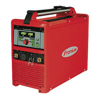
Fronius MagicWave 3000 Operating Instructions Manual (220 pages)
TIG power source
Brand:
Fronius
| Category:
Portable Generator
| Size: 4 MB
Table of Contents
Special 4-Step Mode: Variant
2
Table of Contents
3
Safety Rules
8
Explanation of Safety Notices
8
General
8
Proper Use
8
Environmental Conditions
9
Obligations of the Operator
9
Obligations of Personnel
9
Mains Connection
9
Protecting Yourself and Others
10
Noise Emission Values
10
Danger from Toxic Gases and Vapours
11
Danger from Flying Sparks
11
Risks from Mains Current and Welding Current
12
Meandering Welding Currents
13
EMC Device Classifications
13
EMC Measures
13
EMF Measures
14
Specific Hazards
14
Requirement for the Shielding Gas
15
Danger from Shielding Gas Cylinders
15
Danger from Escaping Shielding Gas
16
Safety Measures at the Installation Location and During Transport
16
Safety Measures in Normal Operation
16
Commissioning, Maintenance and Repair
17
Safety Inspection
17
Disposal
18
Safety Symbols
18
Data Protection
18
Copyright
18
General Information
19
General
21
Device Concept
21
Functional Principle
21
Application Areas
21
System Components
22
General
22
Overview
22
Control Elements and Connections
23
Description of the Control Panels
25
General
25
Safety
25
Magicwave Comfort Control Panel
25
Transtig Comfort Control Panel
27
Connections, Switches and Mechanical Components
29
Magicwave2200 Comfort
29
Magicwave2500 / 3000 Comfort
30
Magicwave4000 / 5000 Comfort
31
Transtig2200 Comfort
32
Transtig2500 / 3000 Comfort
33
Transtig4000 / 5000 Comfort
34
Installation and Commissioning
35
Minimum Equipment Needed for Welding Task
37
General
37
TIG AC Welding
37
TIG DC Welding
37
Automated TIG Welding
37
MMA Welding
37
Before Installation and Commissioning
38
Safety
38
Utilisation for Intended Purpose
38
Setup Regulations
38
Mains Connection
38
Start-Up
40
Safety
40
Remarks on the Cooling Unit
40
General
40
Connecting the Gas Cylinder
40
Establishing a Ground (Earth) Connection to the Workpiece
41
Connecting the Welding Torch
41
Welding
43
TIG Modes
45
Safety
45
Symbols and Their Explanations
45
2-Step Mode
46
Spot Welding
46
4-Step Mode
47
Special 4-Step Mode: Variant
47
Special 4-Step Mode: Variant
48
Cap Shaping and Cap Overloading
50
Cap-Shaping
50
Cap Overloading
50
TIG Welding
51
Safety
51
Welding Parameters: Display and Navigation
51
Welding Parameters for TIG
51
Preparation
54
TIG Welding
54
Igniting the Arc
56
General
56
Igniting the Arc Using High Frequency(HF Ignition)
56
Touchdown Ignition
57
End of Welding
58
Special Functions and Options
59
Arc Break Watchdog Function
59
Ignition Time-Out Function
59
TIG Pulsing
59
Tacking Function
60
TIG Cold-Wire Welding
61
MMA Welding
63
Safety
63
Welding Parameters: Display and Navigation
63
Welding Parameters for Rod Electrodes
64
Preparation
65
MMA Welding
66
Hotstart Function
68
Starting Current < 100 % (Softstart)
68
Anti-Stick Function
68
Welding Job
70
Safety
70
Welding Parameters: Display and Navigation
70
Welding Parameters for TIG
70
Welding Parameters for Rod Electrodes
73
Preparation
75
Welding Job
76
Finishing the Welding Job
78
Saving Settings as a Job
80
General
80
Preparation
80
Saving Settings as a Job
81
Finish Saving Job
86
Setup Settings
89
The Setup Menu
91
General
91
Overview
91
TIG Setup
92
Opening the TIG Setup
92
Changing Welding Parameters
93
Exiting TIG Setup
94
Welding Parameters in the TIG Setup
95
TIG Setup 2Nd
98
Opening the TIG Setup 2Nd
98
Changing Welding Parameters
98
Exiting TIG Setup 2Nd
99
Welding Parameters in the TIG Setup 2Nd
101
AC Setup
105
General
105
Open the AC Setup
105
Changing Welding Parameters
106
Exiting AC Setup
107
Welding Parameters in AC Setup
108
AC Setup 2Nd
110
General
110
Opening the AC Setup 2Nd
110
Changing Welding Parameters
110
Exiting AC Setup 2Nd
112
Welding Parameters in AC Setup 2Nd
113
Gas Setup
115
General
115
Opening the Gas Setup
115
Changing Welding Parameters
116
Exiting Gas Setup
117
Gas Setup Parameters
118
Cold Wire Setup
121
General
121
Opening the AC Setup
121
Changing Welding Parameters
122
Exiting the Cold Wire Setup
123
Welding Parameters in the Cold Wire Setup
124
Calibrating Push-Pull Unit
126
General
126
Calibrating the Push-Pull Unit
126
General
128
Service Codes During Calibration of the Push-Pull Unit
129
Rod Elec. Setup (Rod Electrode Setup)
133
Open the Rod Electrode Setup
133
Changing Welding Parameters
134
Exiting Rod Electrode-Setup
135
Rod Electrode Setup Parameters
135
Rod Elec. Setup 2Nd (Rod Electrode Setup 2Nd)
137
Opening the Rod Electrode Setup 2Nd
137
Changing Welding Parameters
137
Exiting Rod Electrode Setup 2Nd
138
Rod Electrode Setup 2Nd Welding Parameters
140
AC Setup (for Rod Electrodes)
143
General
143
Opening the AC Setup
143
Changing Welding Parameters
144
Exiting AC Setup
145
Welding Parameters in AC Setup
145
Job
147
General
147
Opening the Job Set-Up Menu
147
Save / Retrieve
147
Overview
148
Optimising a Job
149
Renaming a Job
151
Finish Optimising Job
153
Adjustable TIG Parameters
154
Adjustable Rod Electrode Parameters
159
Deleting a Job
163
Basic Setting
166
General
166
Opening the Basic Settings
166
Changing Welding Parameters
167
Exiting Basic Settings
168
Basic Setting Parameters
169
Info
170
General
170
Calling up the Info Screen
170
Exiting the Info Screen
171
Entries on the Info Screen
172
Lock Keys
173
General
173
Unlock Keys Again
174
Factory - for Resetting the Welding Machine
175
General
175
L/R Alignment
177
Abbreviations
177
General Information on Welding Circuit Inductivity L
177
General Information on Welding Circuit Resistance R
177
Troubleshooting and Maintenance
181
Troubleshooting
183
General
183
Safety
183
Displayed Service Codes
183
Service Codes Displayed in Conjunction with the Digital Gas Control Option
189
Displayed Service Codes in Conjunction with Cold Wire-Feed Unit
189
Power Source - Troubleshooting
190
Care, Maintenance and Disposal
193
General
193
Safety
193
At Every Start-Up
193
Every 2 Months
193
Every 6 Months
194
Disposal
194
Appendix
195
Average Consumption Values During Welding
197
Average Wire Electrode Consumption During MIG/MAG Welding
197
Average Shielding Gas Consumption During MIG/MAG Welding
197
Average Shielding Gas Consumption During TIG Welding
197
Technical Data
198
Special Voltages
198
Advertisement
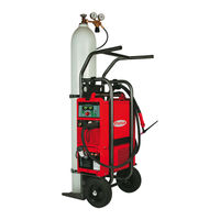
Fronius MagicWave 3000 Operating Instructions Manual (140 pages)
TIG Power Source
Brand:
Fronius
| Category:
Welding System
| Size: 10 MB
Table of Contents
Table of Contents
5
Safety Rules
9
Explanation of Safety Symbols
9
General
9
Proper Use
10
Environmental Conditions
10
Obligations of the Operator
10
Obligations of Personnel
11
Mains Connection
11
Protecting Yourself and Others
11
Noise Emission Values
12
Danger from Toxic Gases and Vapours
12
Danger from Flying Sparks
13
Risks from Mains Current and Welding Current
13
Meandering Welding Currents
14
EMC Device Classifications
14
EMC Measures
15
EMF Measures
15
Specific Hazards
15
Factors Affecting Welding Results
17
Danger from Shielding Gas Cylinders
17
Safety Measures at the Installation Location and During Transport
17
Safety Measures in Normal Operation
18
Commissioning, Maintenance and Repair
19
Safety Inspection
19
Disposal
19
Safety Symbols
20
Data Protection
20
Copyright
20
General Information
21
General
23
Device Concept
23
Functional Principle
24
Field of Application
24
Warning Notices on the Device
25
System Components
26
General
26
Overview
26
Control Elements and Connections
27
Description of the Control Panels
29
General
29
Safety
29
Overview
29
Magicwave Control Panel
30
Transtig Control Panel
34
Key Combinations - Special Functions
38
General
38
Displaying the Software Version, Operating Time and Coolant Flow
38
Connections, Switches and Mechanical Components
39
Magicwave1700 / 2200
39
Magicwave2500 / 3000
40
Magicwave4000 / 5000
41
Transtig 2200
42
Transtig2500 / 3000
43
Transtig4000 / 5000
44
Installation and Commissioning
45
Minimum Equipment Needed for Welding Task
47
General
47
TIG AC Welding
47
TIG DC Welding
47
MMA Welding
47
Before Installation and Commissioning
48
Safety
48
Utilisation for Intended Purpose
48
Setup Regulations
48
Mains Connection
48
Generator-Powered Operation (MW 1700 / 2200, TT2200)
49
Connecting up the Mains Cable on US Power Sources
50
General
50
Stipulated Mains Cables and Strain-Relief Devices
50
Safety
50
Connecting the Mains Cable
50
Replacing the Strain-Relief Device
51
Start-Up
53
Safety
53
Remarks on the Cooling Unit
53
General
53
Connecting the Gas Cylinder
53
Establishing a Ground (Earth) Connection to the Workpiece
54
Connecting the Welding Torch
54
Welding
55
TIG Modes
57
Safety
57
Symbols and Their Explanations
57
2-Step Mode
58
Special 4-Step Mode: Variant 4
59
Cap Shaping and Cap Overloading
60
Cap Shaping
60
TIG Welding
61
Safety
61
Welding Parameters
61
Preparation
62
TIG Welding
62
Igniting the Arc
64
General
64
Igniting the Arc Using High Frequency(HF Ignition)
64
Touchdown Ignition
65
End of Welding
66
Special Functions and Options
67
Arc Break Watchdog Function
67
Ignition Time-Out Function
67
Tacking Function
67
MMA Welding
69
Safety
69
Preparation
69
Manual Metal Arc Welding
69
Hotstart Function
70
Anti-Stick Function
71
Setup Settings
73
The Setup Menu
75
General
75
Overview
75
Shielding Gas Setup Menu
76
General
76
Opening the Protective Gas Shield Set-Up Menu
76
Changing Welding Parameters
76
Exiting the Set-Up Menu
76
Welding Parameters in the Protective Gas Shield Set-Up Menu
76
TIG Setup Menu
78
Opening the TIG Set-Up Menu
78
Changing Welding Parameters
78
Exiting the Set-Up Menu
78
Welding Parameters in the TIG Set-Up Menu
78
Rod Electrode Setup Menu
81
Open the Rod Electrode Set-Up Menu
81
Changing Welding Parameters
81
Exiting the Set-Up Menu
81
Welding Parameters in the Rod Electrode Set-Up Menu
81
Rod Electrode Setup Menu: Level 2
83
Opening the Rod Electrode Set-Up Menu Level 2
83
Changing Welding Parameters
83
Exiting the Rod Electrode Set-Up Menu - Level 2
83
Welding Parameters in the Rod Electrode Set-Up Menu Level
83
Troubleshooting and Maintenance
87
Troubleshooting
89
General
89
Safety
89
Displayed Service Codes
89
Power Source - Troubleshooting
92
Care, Maintenance and Disposal
94
General
94
Safety
94
At Every Start-Up
94
Every 2 Months
94
Every 6 Months
94
Disposal
95
Appendix
97
Technical Data
99
Special Voltages
99
Magicwave1700 / 2200
99
Magicwave2500 / 3000
100
Magicwave 2500 / 3000 MV
100
Magicwave4000 / 5000
101
Magicwave 4000 / 5000 MV
102
Transtig 2200
103
Transtig2500 / 3000
104
Transtig 2500 / 3000 MV
105
Transtig4000 / 5000
106
Transtig 4000 / 5000 MV
107
Explanation of Footnotes
107
Terms and Abbreviations Used
108
General
108
Terms and Abbreviations a - F
108
Terms and Abbreviations G - H
108
Terms and Abbreviations I - U
109
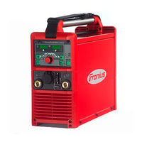
Fronius MagicWave 3000 Operating Instructions Manual (124 pages)
Brand:
Fronius
| Category:
Welding System
| Size: 3 MB
Table of Contents
Welding Parameters in the Rod Electrode Setup Menu - Level
2
Table of Contents
3
Special 4-Step Mode: Variant
4
Safety Rules
7
Explanation of Safety Notices
7
General
7
Proper Use
8
Environmental Conditions
8
Obligations of the Operator
8
Obligations of Personnel
8
Mains Connection
9
Protecting Yourself and Others
9
Noise Emission Values
10
Danger from Toxic Gases and Vapours
10
Danger from Flying Sparks
10
Risks from Mains Current and Welding Current
11
Meandering Welding Currents
12
EMC Device Classifications
12
EMC Measures
12
EMF Measures
13
Specific Hazards
13
Requirement for the Shielding Gas
14
Danger from Shielding Gas Cylinders
14
Danger from Escaping Shielding Gas
15
Safety Measures at the Installation Location and During Transport
15
Safety Measures in Normal Operation
16
Commissioning, Maintenance and Repair
16
Safety Inspection
17
Disposal
17
Safety Symbols
17
Data Protection
17
Copyright
18
General Information
19
General
21
Device Concept
21
Functional Principle
22
Application Areas
22
Warning Notices on the Device
23
System Components
24
General
24
Overview
24
Control Elements and Connections
25
Description of the Control Panels
27
General
27
Safety
27
Overview
28
Magicwave Control Panel
29
Transtig Control Panel
34
Key Combinations - Special Functions
38
General
38
Displaying the Software Version, Operating Time and Coolant Flow
38
Connections, Switches and Mechanical Components
39
Magicwave1700 / 2200
39
Magicwave2500 / 3000
40
Magicwave4000 / 5000
41
Transtig 2200
42
Transtig2500 / 3000
43
Transtig4000 / 5000
44
Installation and Commissioning
45
Minimum Equipment Needed for Welding Task
47
General
47
TIG AC Welding
47
TIG DC Welding
47
MMA Welding
47
Before Installation and Commissioning
48
Safety
48
Utilisation for Intended Purpose
48
Setup Regulations
48
Mains Connection
48
Generator-Powered Operation (MW 1700 / 2200, TT 2200)
49
Connecting up the Mains Cable on US Power Sources
50
General
50
Stipulated Mains Cables and Strain-Relief Devices
50
Safety
50
Connecting the Mains Cable
50
Replacing the Strain-Relief Device
52
Start-Up
53
Safety
53
Remarks on the Cooling Unit
53
General
53
Connecting the Gas Cylinder
53
Establishing a Ground (Earth) Connection to the Workpiece
54
Connecting the Welding Torch
54
Welding
55
TIG Modes
57
Safety
57
Symbols and Their Explanations
57
2-Step Mode
58
Cap Shaping and Cap Overloading
60
Cap-Shaping
60
TIG Welding
61
Safety
61
Welding Parameters
61
Preparation
62
TIG Welding
62
Igniting the Arc
64
General
64
Igniting the Arc Using High Frequency(HF Ignition)
64
Touchdown Ignition
65
End of Welding
66
Special Functions and Options
67
Arc Break Watchdog Function
67
Ignition Time-Out Function
67
Tacking Function
67
MMA Welding
69
Safety
69
Preparation
69
Hotstart Function
71
Anti-Stick Function
71
Setup Settings
73
The Setup Menu
75
General
75
Overview
75
Shielding Gas Setup Menu
76
General
76
Opening the Protective Gas Shield Set-Up Menu
76
Changing Welding Parameters
76
Exiting the Set-Up Menu
76
Welding Parameters in the Protective Gas Shield Set-Up Menu
76
TIG Setup Menu
78
Opening the TIG Set-Up Menu
78
Changing Welding Parameters
78
Exiting the Set-Up Menu
78
Rod Electrode Setup Menu
82
Open the Rod Electrode Set-Up Menu
82
Changing Welding Parameters
82
Exiting the Set-Up Menu
82
Welding Parameters in the Rod Electrode Set-Up Menu
82
Rod Electrode Setup Menu: Level 2
84
Opening the Rod Electrode Set-Up Menu Level
84
Changing Welding Parameters
84
Exiting the Rod Electrode Set-Up Menu - Level
84
Troubleshooting and Maintenance
87
Troubleshooting
89
General
89
Safety
89
Displayed Service Codes
89
Power Source - Troubleshooting
92
Care, Maintenance and Disposal
94
General
94
Safety
94
At Every Start-Up
94
Every 2 Months
94
Every 6 Months
95
Disposal
95
Appendix
97
Average Consumption Values During Welding
99
Average Wire Electrode Consumption During MIG/MAG Welding
99
Average Shielding Gas Consumption During MIG/MAG Welding
99
Average Shielding Gas Consumption During TIG Welding
99
Technical Data
100
Special Voltages
100
Overview with Critical Raw Materials, Year of Production of the Device
100
Magicwave 1700
100
Magicwave 2200
101
Magicwave 2500
102
Magicwave 3000
103
Magicwave 2500 MV
104
Magicwave 3000 MV
105
Magicwave 4000
106
Magicwave 5000
107
Magicwave 4000 MV
108
Magicwave 5000 MV
109
Transtig 2200
111
Advertisement
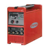
Fronius MagicWave 3000 Operating Instructions Manual (112 pages)
TIG
Brand:
Fronius
| Category:
Portable Generator
| Size: 15 MB
Table of Contents
Table of Contents
3
Safety Rules
7
Explanation of Safety Notices
7
General
7
Proper Use
7
Environmental Conditions
8
Obligations of the Operator
8
Obligations of Personnel
8
Mains Connection
8
Protecting Yourself and Others
9
Noise Emission Values
9
Danger from Toxic Gases and Vapours
10
Danger from Flying Sparks
10
Risks from Mains Current and Welding Current
10
Meandering Welding Currents
11
EMC Device Classifications
12
EMC Measures
12
EMF Measures
13
Specific Hazards
13
Requirement for the Shielding Gas
14
Danger from Shielding Gas Cylinders
14
Danger from Escaping Shielding Gas
14
Safety Measures at the Installation Location and During Transport
15
Safety Measures in Normal Operation
15
Commissioning, Maintenance and Repair
16
Safety Inspection
16
Disposal
16
Safety Symbols
17
Data Protection
17
Copyright
17
General Information
19
General
21
Device Concept
21
Functional Principle
22
Application Areas
22
Warning Notices on the Device
23
System Components
24
General
24
Overview
24
Control Elements and Connections
25
Description of the Control Panels
27
General
27
Safety
27
Overview
28
Magicwave Control Panel
29
Transtig Control Panel
33
Key Combinations - Special Functions
37
General
37
Displaying the Software Version, Operating Time and Coolant Flow
37
Connections, Switches and Mechanical Components
38
Magicwave1700 / 2200
38
Magicwave2500 / 3000
39
Magicwave4000 / 5000
40
Transtig 2200
41
Transtig2500 / 3000
42
Transtig4000 / 5000
43
Installation and Commissioning
45
Minimum Equipment Needed for Welding Task
47
General
47
TIG AC Welding
47
TIG DC Welding
47
MMA Welding
47
Before Installation and Commissioning
48
Safety
48
Utilisation for Intended Purpose
48
Setup Regulations
48
Mains Connection
48
Generator-Powered Operation (MW 1700 / 2200, TT2200)
49
Connecting up the Mains Cable on US Power Sources
50
General
50
Stipulated Mains Cables and Strain-Relief Devices
50
Safety
50
Connecting the Mains Cable
50
Replacing the Strain-Relief Device
51
Start-Up
53
Safety
53
Remarks on the Cooling Unit
53
General
53
Connecting the Gas Cylinder
53
Establishing a Ground (Earth) Connection to the Workpiece
54
Connecting the Welding Torch
54
Welding
55
TIG Modes
57
Safety
57
Symbols and Their Explanations
57
Cap Shaping and Cap Overloading
63
Cap-Shaping
63
TIG Welding
64
Safety
64
Welding Parameters
64
Preparation
65
TIG Welding
65
Igniting the Arc
67
General
67
Igniting the Arc Using High Frequency(HF Ignition)
67
Touchdown Ignition
68
End of Welding
69
Special Functions and Options
70
Arc Break Watchdog Function
70
Ignition Time-Out Function
70
Tacking Function
70
MMA Welding
72
Safety
72
Preparation
72
Hotstart Function
73
Anti-Stick Function
74
2 Step Mode
58
4 Step Mode
60
Special 4-Step Mode: Variant 4
62
Setup Settings
75
The Setup Menu
77
General
77
Overview
77
Shielding Gas Setup Menu
78
General
78
Opening the Protective Gas Shield Set-Up Menu
78
Changing Welding Parameters
78
Exiting the Set-Up Menu
78
Welding Parameters in the Protective Gas Shield Set-Up Menu
78
TIG Setup Menu
80
Opening the TIG Set-Up Menu
80
Changing Welding Parameters
80
Exiting the Set-Up Menu
80
Welding Parameters in the TIG Setup Menu
80
Rod Electrode Setup Menu
83
Open the Rod Electrode Set-Up Menu
83
Changing Welding Parameters
83
Exiting the Set-Up Menu
83
Welding Parameters in the Rod Electrode Set-Up Menu
83
Rod Electrode Setup Menu: Level 2
85
Opening the Rod Electrode Set-Up Menu Level 2
85
Changing Welding Parameters
85
Exiting the Rod Electrode Set-Up Menu - Level 2
85
Welding Parameters in the Rod Electrode Setup Menu - Level 2
85
Troubleshooting and Maintenance
89
Troubleshooting
91
General
91
Safety
91
Displayed Service Codes
91
Power Source - Troubleshooting
94
Care, Maintenance and Disposal
96
General
96
Safety
96
At Every Start-Up
96
Every 2 Months
96
Every 6 Months
97
Disposal
97
Fronius MagicWave 3000 Manual (72 pages)
TIG power source
Brand:
Fronius
| Category:
Welding System
| Size: 1 MB
Table of Contents
Special 4-Step: Version
2
Table of Contents
3
Safety Instructions
6
Explanation of Safety Instructions
6
General
6
Intended Use
6
Environmental Conditions
7
Obligations of the Operating Company
7
Obligations of Personnel
7
Grid Connection
7
Personal Protection and Protection of Others
8
Data Regarding Noise Emission Values
8
Danger from Toxic Gases and Vapors
9
Danger from Flying Sparks
9
Risks from Grid Current and Welding Current
10
Stray Welding Currents
11
EMC Device Classifications
11
EMC Measures
11
EMF Measures
12
Particular Hazard Areas
12
Undesired Welding Results
13
Danger from Shielding Gas Cylinders
13
Safety Measures at the Setup Location and During Transport
14
Safety Measures in Normal Operation
14
Maintenance and Repair
15
Safety Inspection
15
Disposal
15
Safety Symbols
16
Data Backup
16
Copyright
16
General
17
Principle
17
Device Concept
17
Field of Application
17
Warning Notice on the Device
18
Minimum Equipment for Welding Operations
19
General
19
TIG AC Welding
19
TIG DC Welding
19
Manual Metal Arc Welding
19
System Components
20
General
20
Overview
20
Control Panel
21
General
21
Overview
21
Magicwave Control Panel
22
Control Panel for Transtig
24
Connections, Switches and System Extensions
27
Magicwave / Transtig Connections with Fronius Welding Torch Central Connector F
27
Magicwave / Transtig Connections with Welding Torch Central Connector GWZ
28
Magicwave / Transtig Connections with Welding Torch Central Connector GWZ
29
Before Installation
30
Safety
30
Intended Use
30
Setup Regulations
30
Mains Operation
30
Generator-Powered Operation
31
Commissioning
32
General
32
Notes on the Cooling Unit
32
Connecting the Shielding Gas Cylinder
32
Establish a Connection with the Workpiece
33
Connect the Welding Torch
33
TIG Operating Modes
34
General
34
Symbols and Explanations
34
2-Step
35
Special 2-Step
35
4-Step
36
4-Step with Intermediate Lowering
36
Special 4-Step: Version
37
Special 4-Step: Version
39
TIG Welding
40
Safety
40
Preparation
40
Select Operating Mode
41
Select Process
41
Cap-Shaping (Magicwave)
42
Welding Parameter Setting
42
Adjust the Shielding Gas Quantity
42
Ignition of the Arc - General
42
TIG Synchronous Welding AC (Magicwave)
42
HF Ignition
43
Contact Ignition
44
Ignition Monitoring
45
Manual Metal Arc Welding
46
Safety
46
Preparation
46
Select Operating Mode
47
Select Process (Magicwave)
47
Welding Parameter Setting
47
Remote Control
49
Safety
49
General
49
AC Remote Control TR 53Mc
49
TIG Pulse Remote Control TR 50Mc
50
TIG Foot Remote Control TR 52Mc
51
TIG Spot Welding Remote Control TR 51Mc
52
Remote Control TP MC / TP MC-CEL
52
Working with Program Levels
56
Overview
56
Program Level Preferences
57
Access
57
Select and Change Setup Parameters
57
Available TIG Parameters
57
Program Levels P1 - P3
61
Access
61
Select and Change Setup Parameters
61
Program Level AC Parameters P3 (Magicwave)
62
Fault Diagnosis and Correction
63
Safety
63
Displayed Service Codes
63
Fronius MagicWave 3000 Operating Instructions/Spare Parts List (121 pages)
TIG power source
Brand:
Fronius
| Category:
Portable Generator
| Size: 4 MB
Table of Contents
Deutsch
17
Table of Contents
17
Allgemeines
18
Inbetriebnahme Allgemein
18
Beschreibung der Bedienungselemente
19
Brennermontage eines Wassergekühlten WIG-Schweissbrenners
25
Brennermontage eines Gasgekühlten WIG-Schweissbrenners
26
Kühlgerät FK 2600 / 2601
26
Aufstellbestimmungen
27
Arbeiten mit den Programmebenen
27
Fernreglerbetrieb Allgemein
28
AC-Fernregler TR 53Mc
28
WIG-Pulsfernregler TR 50Mc
29
WIG-Fussfernregler TR 52Mc
30
WIG-Punktierfernregler TR 51Mc
31
Fernregler TP MC / TP MC-CEL
31
WIG-Schweissen mit Hochfrequenzzündung (HF)
33
WIG-Schweissen mit Berührungszünden (ohne HF)
34
WIG-Synchronschweissen AC
34
Elektroden-Handschweissen
34
Austausch der Elektronik UTC-AC Bzw. UTC-DC
35
Pflege und Wartung
35
Beschreibung der Error-Nummern
35
Fehlersuche und Abhilfe
36
Technische Daten
38
English
53
General Remarks
54
Start-Up - General Notes
54
Description of Controls
55
Assembling a Water-Cooled TIG Torch
61
Assembling a Gas-Cooled TIG Torch
62
Cooling Unit FK 2600 / 2601
62
Setting-Up Instructions
63
Working with the Program Levels
63
Remote Control Operation General
64
TR 53 MC A.C. Remote Control Unit
64
TR 50Mc Remote Control Pulsing Unit
65
TR 52Mc Remote Control Pedal Unit
66
Tpmc Remote Control Unit
67
TR 51Mc Remote Control Spot-Welding Unit
67
TIG Welding with High-Frequency Ignition (HF)
69
Manual Electrode Welding
70
TIG Synchronous Welding AC
70
TIG Welding with Contact Ignition (Without HF)
70
Care and Maintenance
71
Description of Error Numbers
71
Exchanging the UTC-AC Resp. UTC-DC Electronic Module
71
Troubleshooting Guide
72
Technical Data
74
Français
89
Généralités
90
Mise en Service Généralités
90
Description des Éléments de Commande
91
Montage D'une Torche de Soudage Tig Refroidie Par L'eau
97
Appareil de Refroidissement FK 2600 / 2601
98
Montage D'une Torche de Soudage Tig Refroidie Par Gaz
98
Dispositions D´installation
99
Travail Avec Les Niveaux de Programme
99
Commande À Distance C.A. TR 53Mc
100
Service de Télécommande Général
100
Commande À Distance TIG Pulse TR 50Mc
101
Commande À Distance TIG À Pedale TR 52Mc
102
Commande À Distance Tpmc
103
Soudage TIG À Amorçage À Haute Fréquence (HF)
105
Soudage Manuel À L´électrode Enrobée
106
Soudage TIG Synchrone C.A
106
Soudage TIG À Amorçage Par Contact (Sans HF)
106
Description des Numéros D´erreur
107
Entretien
107
Remplacement de L'électronique UTC C.A./C.C
107
Diagnostics de Panne Et Remédes
108
Caractéristiques Techniques
110
Liste de Pièces de Rechange
111
Advertisement
Related Products
Fronius MagicWave 2200
Fronius MagicWave 2500
Fronius MagicWave 4000
Fronius MagicWave 5000
Fronius MTG 5300 S
Fronius MTW 500i
Fronius MTB 320i W
Fronius MHP Series
Fronius MHP 550i G ML
Fronius MTG 500i TD
Fronius Categories
Inverter
Welding System
Welding Accessories
Battery Charger
Measuring Instruments
More Fronius Manuals
Login
Sign In
OR
Sign in with Facebook
Sign in with Google
Upload manual
Upload from disk
Upload from URL