Fronius TPS 270i C Operating Instructions Manual
Mig/mag power source
Hide thumbs
Also See for TPS 270i C:
- Quick manual (2 pages) ,
- Operating instructions manual (152 pages) ,
- Operating instructions manual (172 pages)
Table of Contents
Troubleshooting

Related Manuals for Fronius TPS 270i C


Summary of Contents for Fronius TPS 270i C
- Page 1 / Perfect Charging / Perfect Welding / Solar Energy Operating Instructions TPS 270i C MIG/MAG Power source 42,0426,0206,EN 008-04052017 Fronius prints on elemental chlorine free paper (ECF) sourced from certified sustainable forests (FSC).
- Page 3 Thank you for the trust you have placed in our company and congratulations on buying this high-quality Fronius product. These instructions will help you familiarise yourself with the product. Reading the instructions carefully will enable you to learn about the many different features it has to offer.
-
Page 5: Table Of Contents
Contents Safety rules ..............................Explanation of safety symbols ......................General ..............................Proper use ............................Environmental conditions........................Obligations of the operator........................Obligations of personnel ........................Mains connection ..........................Residual current protective device......................Protecting yourself and others ......................Noise emission values .......................... Danger from toxic gases and vapours .................... - Page 6 F1 and F2 special function parameters....................The Favourites button ........................... Connections, switches and mechanical components ................Connections, switches and mechanical components ................Installation and commissioning Minimum equipment needed for welding task.................... General ..............................MIG/MAG gas-cooled welding ......................MIG/MAG water-cooled welding ......................Manual CMT welding ..........................
- Page 7 Keylock ..............................112 Power source website Power source website..........................115 General remarks ........................... 115 Calling up the power source website ....................115 User password ............................115 Settings ..............................116 Language selection..........................116 Fronius ..............................117 Overview ..............................118 Overview ............................... 118...
- Page 8 Technical data............................137 Explanation of the term "duty cycle" ..................... 137 Special voltages............................ 137 TPS 270i C............................138 TPS 270i C /nc............................139 TPS 270i C /MV/nc ..........................140 TPS 270i C /S/nc ..........................142 Spare parts list: TPS 270i C........................143...
-
Page 9: Safety Rules
Safety rules Explanation of DANGER! Indicates immediate and real danger. If it is not avoided, death or se- safety symbols rious injury will result. WARNING! Indicates a potentially dangerous situation. Death or serious injury may result if appropriate precautions are not taken. CAUTION! Indicates a situation where damage or injury could occur. -
Page 10: Proper Use
Proper use The device is to be used exclusively for its intended purpose. The device is intended solely for the welding processes specified on the rating plate. Any use above and beyond this purpose is deemed improper. The manufac- turer shall not be held liable for any damage arising from such usage. Proper use includes: carefully reading and following all the instructions given in the operating instructions... -
Page 11: Obligations Of Personnel
Obligations of Before using the device, all persons instructed to do so undertake: personnel to observe the basic instructions regarding safety at work and accident prevention to read these operating instructions, especially the "Safety rules" section and sign to confirm that they have understood them and will follow them. Before leaving the workplace, ensure that people or property cannot come to any harm in your absence. -
Page 12: Noise Emission Values
harmful welding fumes and gases Anyone working on the workpiece while welding is in progress must wear suit- able protective clothing with the following properties: flame-resistant insulating and dry covers the whole body, is undamaged and in good condition safety helmet trousers with no turn-ups Protective clothing refers to a variety of different items. -
Page 13: Danger From Flying Sparks
If there is any doubt about whether the extraction capacity is sufficient, the measured toxic emission values should be compared with the permissible limit values. Amongst others, the following components are responsible for the degree of toxicity of welding fumes: Metals used for the workpiece Electrodes Coatings... -
Page 14: Meandering Welding Currents
The electrode (rod electrode, tungsten electrode, welding wire, etc.) must never be immersed in liquid for cooling Never touch the electrode when the power source is switched on. Double the open circuit voltage of a power source can occur between the welding electrodes of two power sources. -
Page 15: Emc Device Classifications
EMC Device Clas- Devices in emission class A: sifications Are only designed for use in industrial settings Can cause line-bound and radiated interference in other areas Devices in emission class B: Satisfy the emissions criteria for residential and industrial areas. This is also true for residential areas in which the energy is sup- plied from the public low-voltage mains. -
Page 16: Specific Hazards
Specific hazards Keep hands, hair, clothing and tools away from moving parts. For example: Fans Cogs Rollers Shafts Wirespools and welding wires Do not reach into the rotating cogs of the wire drive or into rotating drive com- ponents. Covers and side panels may only be opened/removed while maintenance or repair work is being carried out. -
Page 17: Factors Affecting Welding Results
If the device has a carrying strap or handle, this is intended solely for carrying by hand. The carrying strap is not to be used if transporting with a crane, coun- terbalanced lift truck or other mechanical hoist. All lifting accessories (straps, handles, chains, etc.) used in connection with the device or its components must be tested regularly (e.g. -
Page 18: Danger From Escaping Shielding Gas
Danger from es- Risk of suffocation from the uncontrolled escape of shielding gas caping shielding Shielding gas is colourless and odourless and, in the event of a leak, can dis- place the oxygen in the ambient air. Ensure an adequate supply of fresh air with a ventilation rate of at least 20 m³/hour. -
Page 19: Commissioning, Maintenance And Repair
Always fasten the shielding gas cylinder securely and remove it beforehand if the device is to be transported by crane. Only the manufacturer's original coolant is suitable for use with our devices due to its properties (electrical conductibility, anti-freeze agent, material com- patibility, flammability, etc.). -
Page 20: Disposal
(e.g. relevant product standards of the EN 60 974 series). Fronius International GmbH hereby declares that the device is compliant with Directive 2014/53/EU. The full text on the EU Declaration of Conformity can be found at the following address: http://www.fronius.com Devices marked with the CSA test mark satisfy the requirements of the rele- vant standards for Canada and the USA. -
Page 21: General Information
General information... -
Page 23: General
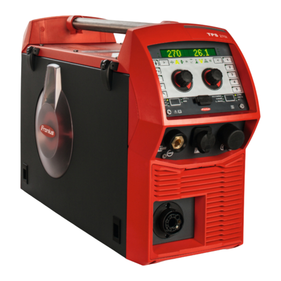
General Device concept The TPS 270i C MIG/MAG power source is a completely digitised, microprocessor- controlled inverter power source with integ- rated 4-roller wire drive. The modular design and potential for sys- tem add-ons ensure a high degree of flexi- bility. -
Page 24: Warning Notices On The Device
Warning notices Warning notices and safety symbols are affixed to power sources with the CSA test mark on the device for use in North America (USA and Canada). These warning notices and safety symbols must not be removed or painted over. They warn against operating the device incorrectly, as this may result in serious injury and damage. - Page 25 Do not dispose of used devices with domestic waste. Dispose of them accord- ing to the safety rules. Keep hands, hair, clothing and tools away from moving parts. For example: Cogs Feed rollers Wirespools and welding wires Do not reach into the rotating cogs of the wire drive or into rotating drive com- ponents.
-
Page 26: Welding Processes, Processes And Welding Characteristics
Welding processes, processes and welding charac- teristics General TPSi power sources contain a selection of welding processes, procedures and welding characteristics that enable a wide range of materials to be processed in the most effective way. Welding charac- When selecting the filler metal, various process-optimised welding characteristics are teristics available depending on the welding process and shielding gas combination. -
Page 27: Summary Of Mig/Mag Pulse Synergic Welding
Special welding characteristic properties provided by additional hardware CMT mix Additional hardware: CMT drive unit Characteristic with process switch between pulsed and CMT, where the CMT process is initiated by wire movement reversal. mix drive Additional hardware: PushPull drive unit Characteristic with process switch between pulsed and dip transfer arc, where the dip transfer arc is initiated by wire movement reversal. -
Page 28: Summary Of The Lsc Process
Summary of the LSC = Low Spatter Control LSC process LSC is a new, low-spatter dip transfer arc process.The current is reduced before breaking the short-circuit bridge; re-ignition takes place at significantly lower welding current values. Summary of Syn- SynchroPulse is available for all processes (standard/pulsed/LSC/PMC). chroPulse weld- Due to the cyclical change of welding power between two operating points, SynchroPulse achieves a flaking seam appearance and non-continuous heat input. -
Page 29: System Components
OPT/i TPS C polarity reverser OPT/i TPS C SpeedNet Connector Optional second SpeedNet connection socket Installed on the rear of the power source. OPT/i TPS 270i C ext. sensor OPT/i TPS 270i C PushPull OPT/i TPS 270i C TIG OPT/i TPS 270i C Ethernet OPT/i Synergic Lines Option for enabling all special characteristics available on TPSi power sources;... -
Page 31: Controls, Connections And Mechanical Components
Controls, connections and mechani- cal components... -
Page 33: Control Panel
Control panel General Welding parameters can be easily changed and selected using the adjusting dial. The parameters are shown on the display while welding is in progress. The synergic function ensures that other welding parameters are also adjusted whenever an individual parameter is changed. NOTE! As a result of firmware updates, you may find that your device has certain functions that are not described in these operating instructions, or vice versa. - Page 34 Function Process control parameter indicator For the LSC and PMC welding processes Penetration stabilizer indicator Lights up when the penetration stabilizer is active Arc length stabilizer indicator Lights up when the arc length stabilizer is active Left parameter selection The corresponding indicator lights up when a parameter is selected. The following parameters can be selected by pressing the button: Material thickness * in mm or inches...
- Page 35 Function Right parameter selection The corresponding indicator lights up when a parameter is selected. The following parameters can be selected by pressing the button: Arc length correction For correcting the arc length Welding voltage * in V Before the start of welding, the machine automatically displays a standard value based on the programmed parameters.
- Page 36 Function Welding process selection The corresponding LED lights up when a welding process is selected. The following welding processes can be selected by pressing the button: PULS SYNERGIC (MIG/MAG pulse synergic welding) SYNERGIC (MIG/MAG standard synergic welding) MANUAL (MIG/MAG standard manual welding) LSC/PMC (LSC = Low Spatter Control, PMC = Pulse Multi Control) Depending on which function package is enabled STICK/TIG (MMA welding/TIG welding)
-
Page 37: Displaying Plain Text For Parameters
Displaying plain The left adjusting dial can be used to display the corresponding plain text for each param- text for parame- eter abbreviation shown on the display. ters Example: Parameter or entry from the Setup menu has been selected using the right adjusting dial;... -
Page 38: F1/F2 Special Function Parameters, Favourites Button
F1/F2 special function parameters, Favourites but- F1 and F2 special Setting F1 and F2 special function parameters function parame- I-S [%] ters ~ 3 sec. ~ 3 sec. Example: the selected parameter I-S is assigned to F1 Select the desired parameter in the Setup menu Further information on the Setup menu can be found from page 83 To assign the selected parameter to F1 or F2, press the parameter selection button for approx. - Page 39 Retrieving F1 and F2 special function parameters I-S [%] ~ 3 sec. Press the parameter selection button until F1 or F2 lights up: F1 ... left parameter selection F2 ... right parameter selection The stored parameter is shown first, then the currently set value of the parameter. Change the value of the parameter by turning the adjusting dial: F1 ...
-
Page 40: The Favourites Button
The Favourites Assigning the Favourites button button Individual parameters or parent folders from the Setup menu can be assigned to the Fa- vourites button. These parameters or parent folders can then be called up directly using the control panel. ~ 3 sec. Example: The selected SynchroPulse folder is assigned to the Favourites button Select the desired parameter or the desired parent folder in the Setup menu Further information on the Setup menu can be found from page 83... - Page 41 Deleting favourites > 5 sec. Press the Favourites button for at least 5 seconds: The stored parameter or folder is deleted and and X are shown on the display: The Favourites button can also be assigned in the Setup menu (page 107).
-
Page 42: Connections, Switches And Mechanical Components
Connections, switches and mechanical components Connections, switches and me- chanical compo- nents (11) (10) Front Rear (12) (13) Side view Function Control panel with display For operating the power source (+) current socket with bayonet latch SpeedNet connection socket For connecting external system components (e.g. remote controls, etc.) Welding torch connection socket For connecting the welding torch (-) current socket with bayonet latch... - Page 43 Function (10) Mains cable with strain relief device (11) Mains switch For switching the power source on and off (12) Wirespool holder with brake For holding standard wirespools weighing up to 19 kg (41.89 lb.) and with a max. diameter of 300 mm (11.81 in.) (13) 4 roller drive...
-
Page 45: Installation And Commissioning
Installation and commissioning... -
Page 47: Minimum Equipment Needed For Welding Task
Minimum equipment needed for welding task General Depending on which welding process you intend to use, a certain minimum equipment lev- el will be needed in order to work with the power source. The welding processes and the minimum equipment levels required for the welding task are then described. -
Page 48: Before Installation And Commissioning
Before installation and commissioning Safety WARNING! Operating the equipment incorrectly can cause serious injury and damage. Do not use the functions described until you have thoroughly read and understood the following documents: these operating instructions all the operating instructions for the system components, especially the safe- ty rules Proper use The power source may only be used for MIG/MAG, MMA and TIG welding. -
Page 49: Generator-Powered Operation
Generator-pow- The power source is generator-compatible. ered operation The maximum apparent power S of the power source must be known in order to select 1max the correct generator output. The maximum apparent power S of the power source is calculated as follows: 1max 3-phase devices: Single-phase devices:... -
Page 50: Connecting The Mains Cable
General If no mains cable is connected, a mains cable that is suitable for the connection voltage must be fitted before commissioning. Strain-relief devices for the following cable cross-sections are fitted to TPS 270i C power sources: Power source External diameter of cable... - Page 51 6 x TX25 5 x TX25 Tightening torque = 1.2 Nm IMPORTANT! When connecting the cable to the switch, ensure: To route the conductors near to the switch Not to make the conductors unnecessarily long To fit the protective hose supplied over the cable and insert the covered cable into the strain-relief device if cable diameters are small Tightening torque = 1.2 Nm Tightening torque = 1.2 Nm...
- Page 52 5 x TX25, tightening torque = 3 Nm 6 x TX25, tightening torque = 3 Nm...
-
Page 53: Start-Up
Start-up Safety WARNING! An electric shock can be fatal. If the power source is connected to the mains electricity supply during installation, there is a high risk of very serious in- jury and damage. Before carrying out any work on the device make sure that: the power source mains switch is in the "O"... -
Page 54: Establishing A Ground Earth Connection
Establishing a Plug the grounding cable into the (-) ground earth con- current socket nection Lock the grounding cable in place Use the other end of the grounding ca- ble to establish a connection to the workpiece Connecting the grounding cable Connecting the Before connecting the welding torch, check that all cables, lines and hosepacks are welding torch... -
Page 55: Inserting/Replacing Feed Rollers
Inserting/replac- In order to achieve optimum wire electrode feed, the feed rollers must be suitable for the ing feed rollers diameter and alloy of the wire being welded. NOTE! Only use feed rollers that are suitable for the wire electrode. An overview of the feed rollers available and their possible areas of use can be found in the spare parts lists. -
Page 56: Inserting The Wirespool
Inserting the wire- CAUTION! Risk of injury from springiness of spooled wire electrode. While insert- spool ing the wirespool, hold the end of the wire electrode firmly to avoid injuries caused by the wire springing back. CAUTION! Risk of injury from falling wirespool. Make sure that the wirespool is fitted securely to the wirespool holder. -
Page 57: Inserting The Basket-Type Spool
Inserting the bas- CAUTION! Risk of injury from springiness of spooled wire electrode. While insert- ket-type spool ing the basket-type spool, hold the end of the wire electrode firmly to avoid injuries caused by the wire springing back. CAUTION! Risk of injury from falling basket-type spool. Make sure that the bas- ket-type spool and basket-type spool adapter are fitted securely to the wirespool holder. -
Page 58: Feeding In The Wire Electrode
Feeding in the CAUTION! Risk of injury from springiness of spooled wire electrode. When insert- wire electrode ing the wire electrode into the 4-roller drive, hold the end of the wire electrode firmly to avoid injuries caused by the wire springing back. CAUTION! Risk of damage to the welding torch from sharp end of wire electrode. -
Page 59: Setting The Contact Pressure
Setting the con- NOTE! Set the contact pressure in such a way that the wire electrode is not de- tact pressure formed but nevertheless ensures proper wirefeed. Contact pressure U-slot rollers standard values Steel 4 - 5 CrNi 4 - 5 Tubular cored electrodes 2 -3 Adjusting the NOTE! After releasing the torch trigger the wirespool should stop unreeling. -
Page 60: Design Of The Brake
Design of the WARNING! Fitting the equipment brake incorrectly can cause serious inju- ry and damage. Do not dismantle the brake. Maintenance and servicing of brakes is to be carried out by trained, qualified personnel only. The brake is only available as a complete unit. -
Page 61: Welding
Welding... -
Page 63: Mig/Mag Modes
MIG/MAG modes General WARNING! Operating the equipment incorrectly can cause serious injury and damage. Do not use the functions described until you have thoroughly read and understood the following documents: these operating instructions all the operating instructions for the system components, especially the safe- ty rules See the Setup menu for information on settings, setting range and units of measurement for the available parameters. -
Page 64: 2-Step Mode
2-step mode "2-step mode" is suitable for Tacking work Short weld seams Automated and robot welding 4-step mode "4-step mode" is suitable for longer weld seams. Special 4-step "Special 4-step mode" is particularly suitab- mode le for welding aluminium materials. The special slope of the welding current curve takes account of the high thermal conducti- vity of aluminium. -
Page 65: Mig/Mag And Cmt Welding
MIG/MAG and CMT welding Safety WARNING! Operating the equipment incorrectly can cause serious injury and damage. Do not use the functions described until you have thoroughly read and understood the following documents: these operating instructions all the operating instructions for the system components, especially the safe- ty rules WARNING! An electric shock can be fatal. -
Page 66: Retrieving The Currently Set Filler Metal
Retrieving the currently set filler metal Press the "Filler metal info" button The LED on the button lights up and the currently set filler metal is shown on the display: Turn the right adjusting dial The currently set wire diameter is shown on the display: Turn the right adjusting dial The currently set shielding gas is shown on the display: Turn the right adjusting dial... - Page 67 Press the right adjusting dial The first available filler metal is displayed: Select the desired filler metal by turning the right adjusting dial Press the right adjusting dial "diameter?" is shown on the display: * Press the right adjusting dial The first available wire diameter is displayed: Select the desired wire diameter by turning the right adjusting dial Press the right adjusting dial...
-
Page 68: Setting The Welding Parameters
22.8 5O.O Setting the weld- ing parameters Press the button until the desired If necessary: welding parameter lights up Press the button until the desired welding parameter lights up Material thickness Arc length correction Welding current Welding voltage Wire feed speed Pulse/dynamic correction Special function Special function... -
Page 69: Mig/Mag Or Cmt Welding
MIG/MAG or CMT CAUTION! Risk of injury and damage from electric shock and from the wire elec- welding trode emerging from the torch. When pressing the torch trigger: keep the torch away from your face and body do not point the welding torch at people make sure that the wire electrode does not touch any electrically conducting or earthed (grounded) parts, such as the housing, etc. -
Page 70: Mig/Mag And Cmt Welding Parameters
MIG/MAG and CMT welding parameters Welding parame- The following welding parameters can be set and displayed for MIG/MAG pulse synergic ters for MIG/MAG welding, CMT welding and PMC welding: pulse synergic welding, for CMT using the left adjusting dial welding and PMC welding Material thickness Unit... - Page 71 using the right adjusting dial Arc length correction For correcting the arc length Setting range -10 - +10 Factory setting shorter arc length neutral arc length longer arc length Welding voltage Unit Setting range Depends on the welding process and welding program selected Before the start of welding, the machine automatically displays a standard value based on the programmed parameters.
-
Page 72: Welding Parameters For Mig/Mag Standard Synergic Welding And Lsc Welding
Welding parame- The following welding parameters can be set and displayed for MIG/MAG standard syner- ters for MIG/MAG gic welding and LSC welding: standard syner- gic welding and using the left adjusting dial LSC welding Material thickness Unit Setting range 0.1 - 30.0 mm 0.004 - 1.18 Welding current... - Page 73 using the right adjusting dial Arc length correction For correcting the arc length, which is preset by the characteristic or the synergic program Setting range -10 - +10 Factory setting shorter arc length neutral arc length longer arc length Welding voltage Unit Setting range Depends on the welding process and welding program selected...
-
Page 74: Welding Parameters For Mig/Mag Standard Manual Welding
Welding parame- The following welding parameters can be set and displayed for MIG/MAG standard manual ters for MIG/MAG welding: standard manual welding using the left adjusting dial Wire speed For setting a harder, more stable arc Unit m/min Setting range 0.5 - 25 20 - 980 Special function... -
Page 75: Easyjob Mode
EasyJob mode General The 5 EasyJob buttons enable up to 5 operating points to be saved quickly. The current welding settings are saved. EasyJob mode ~ 3 sec. < 3 sec. > 5 sec. Storing EasyJob operating points To store the current welding settings, press one of the EasyJob buttons for approx. 3 seconds. - Page 76 Deleting EasyJob operating points To delete an EasyJob operating point, press the relevant EasyJob button for approx. 5 seconds. After approx. 3 seconds the saved operating point will be overwritten with the current settings and "Job", the button number and a tick are shown on the display. After a total of approx.
-
Page 77: Tig Welding
TIG welding Safety WARNING! Operating the equipment incorrectly can cause serious injury and damage. Do not use the functions described until you have thoroughly read and understood the following documents: these operating instructions all the operating instructions for the system components, especially the safe- ty rules WARNING! An electric shock can be fatal. -
Page 78: Igniting The Arc
Press the "Welding process" button until the LED for the STICK/TIG welding process lights up and "TIG" is shown on the display. After a short time, the currently set welding current is shown on the display. The welding current indicator lights up. The welding voltage is applied to the welding socket with a 3-second time lag. -
Page 79: Finishing Welding
Gradually tilt the welding torch up until the tungsten electrode touches the workpiece Arc ignites when electrode is touched down on workpiece Raise the welding torch and pivot it into the normal position - the arc ignites Carry out welding Arc ignited - welding commences Finishing welding Lift the TIG gas-valve torch away from the workpiece until the arc goes out. -
Page 80: Mma Welding
MMA welding Safety WARNING! Operating the equipment incorrectly can cause serious injury and damage. Do not use the functions described until you have thoroughly read and understood the following documents: these operating instructions all the operating instructions for the system components, especially the safe- ty rules WARNING! An electric shock can be fatal. -
Page 81: Welding Parameters For Manual Metal Arc Welding
STICK Press the "Welding process" button until the LED for the STICK/TIG welding process lights up and "STICK" is shown on the display. After a short time, the currently set welding current and the currently set dynamic are shown on the display. The welding current and dynamic indicators light up. The welding voltage is applied to the welding socket with a 3-second time lag. - Page 82 using the right adjusting dial Dynamic For influencing the short-circuiting dynamic at the moment of droplet transfer Setting range 0 - 100 Factory setting soft, low-spatter arc harder, more stable arc...
-
Page 83: Setup Settings
Setup settings... -
Page 85: Setup Menu - Overview
Setup menu - overview Entering/exiting the Setup menu To enter the Setup menu, press the "Welding process" and "Mode" buttons at the same time "Process parameters" is shown on the display. To exit the Setup menu, press the "Welding process" and "Mode" buttons at the same time... -
Page 86: Setup Menu - Overview
Setup menu - overview Process param. Settings Language xx Start/End Display System back Gas-Setup Process c. Components STICK Unit CLS [s] Standard SynchroPulse UIBS Web-PWreset Process Mix F1/F2 Param. Information R/L-check / align- Favourite iJob xx ment < back System data S4S Guntrigger <... -
Page 87: Process Parameters
Process parameters Process parame- The following process parameters can be set and displayed for the start and end of weld- ters for start of ing: welding/end of welding Starting current For setting the starting current for MIG/MAG welding (e.g. aluminium welding start-up) Unit % (of welding current) Setting range... - Page 88 Final current For setting the final current so that heat build-up towards the end of welding is prevented and the end crater is filled (in the case of aluminium) Unit % (of welding current) Setting range 0 - 200 Factory setting End arc length correction For correcting the arc length at the end of welding Unit...
-
Page 89: Process Parameters For Gas-Setup
Wire retract For setting the wire withdrawal value (= composite value based on backward movement of wire and a time). The wire withdrawal depends on the features of the welding torch. Unit Setting range 0.0 - 10.0 Factory setting Ignition current (manual mode) For setting the ignition current for MIG/MAG standard manual welding Unit Setting range... -
Page 90: Penetration Stabiliser
Penetration stabi- The penetration stabiliser is used to set the max. permitted change in the wire feed speed liser to ensure that the welding current and hence the fusion penetration is kept stable or con- stant with variable stick out. The penetration stabiliser parameter is only available when the WP PMC (Welding Pro- cess Pulse Multi Control) or WP LSC (Welding Process Low Spatter Control) option has been enabled on the power source. - Page 91 Penetration stabiliser = n m/min (activated) I [A] [m/min] t [s] < s Specifying a value for the penetration stabiliser ensures a constant arc length without large current variations if the stick out is changed (s ==> s The penetration (x ) remains virtually unchanged and stable.
-
Page 92: Arc Length Stabilizer
Arc length stabi- Arc length stabilizer lizer The arc length stabilizer forces short arcs, advantageous for welding, via a short-circuit current control and keeps them stable even with a variable stick out or external interfer- ence. The arc length stabilizer welding parameter is only available on the power source if the WP PMC (Welding Process Pulse Multi Control) option has been enabled. -
Page 93: Combination Of Penetration Stabiliser And Arc Length Stabiliser
Arc length stabilizer with change of weld seam profile and position Arc length stabilizer not activated A change of weld seam profile or welding position can negatively affect the welding result Arc length stabilizer activated Since the number and duration of the short circuits is controlled, the properties of the arc stay the same if the weld seam profile or welding position is changed. -
Page 94: Process Parameters For Monitoring And Components
Process parame- The following process parameters can be set and displayed for the system components of ters for monitor- a welding system: ing and components Cooling unit mode To determine whether a cooling unit is to be switched on or off, or operated automatically Setting range eco / auto / on / off (depending on the cooling unit) Factory setting... -
Page 95: Process Parameters For Electrode Setup
Process parame- The following process parameters can be set and displayed for manual metal ters for electrode arc welding: setup Starting current For setting the starting current Unit Setting range 0 - 200 Factory setting Starting current time For setting the length of time for which the starting current is to be active Unit Setting range 0.0 - 2.0... - Page 96 0.1 - 20.0 A/V Parameter "0.1 - 20" is used to set a drooping characteristic (drooping characteris- (5). The setting range extends from 0.1 A / V (very steep) tic with adjustable to 20 A / V (very flat). slope) Setting a flat characteristic (5) is only advisable for cellu- lose electrodes.
-
Page 97: Process Parameters For Tig Setup
Antistick To activate/deactivate the anti-stick function Unit Setting range off / on Factory setting As the arc becomes shorter, the welding voltage may drop so far that the rod electrode will tend to stick. This may also cause the rod electrode to burn out. The anti-stick function prevents the electrode from burning out. - Page 98 At the end of the welding operation, the welding current is switched off automatically if the arc length increases by more than a defined amount. This prevents the arc being unnec- essarily elongated when the TIG gas-valve torch is lifted off the workpiece. Sequence: Welding At the end of the welding action, briefly raise the welding...
-
Page 99: Process Parameters For Synchropulse
Process parame- The following process parameters can be set for SynchroPulse welding: ters for Synchro- Pulse Syn-Puls SynchroPulse To activate/deactivate SynchroPulse Unit Setting range off / on Factory setting Wire speed For setting the average wire speed and therefore the welding power for SynchroPulse Unit m/min (ipm) Setting range... - Page 100 short arc uncorrected arc length longer arc Al-l Arc length correction low For correcting the arc length for SynchroPulse in the lower operating point (= average wire speed minus Delta wire feed) Unit Setting range -10.0 - +10.0 Factory setting short arc uncorrected arc length longer arc...
-
Page 101: Process Parameters For Process Mix
Process parame- The following process parameters for mixed processes can be set under Process Mix: ters for Process PMC mix I [A] [m/min] t [ms] Mixed process between PMC and LSC welding process. A cold LSC process phase follows a hot PMC process phase as part of a cycle. - Page 102 Wire speed taken from the welding parameters Unit m/min (ipm) Setting range 1.0 - 25.0 (40 - 985) The wire speed value can also be specified or changed in the Process Mix parameters. Arc length correction is taken from the welding parameters Setting range -10.0 - +10.0 The arc length correction value can also be specified or changed in the Process Mix pa-...
-
Page 103: R/L Alignment
Lptc Lower power time correction to set the duration of the cold process phase in a mixed process Setting range -10.0 - +10.0 Factory setting Upper and lower power time correction is used to define the relationship between hot and cold process phases. - Page 104 "Remove nozzle" is shown on the display. Remove the gas nozzle from the welding torch Press the right adjusting dial (or press the torch trigger) "Contact workp." is shown on the display. Place the contact tip of the welding torch flush against the workpiece surface Press the torch trigger (or press the right adjusting dial) After a successful measurement, the current values are displayed.
-
Page 105: Settings
Settings General remarks NOTE! As a result of firmware updates, you may find that there are functions available on your unit that are not described in these operating instructions or vice versa. Certain illustrations may also differ slightly from the actual control elements on your device. -
Page 106: Setting The Standards
Setting the stand- Select Setup menu / Settings / View / Standard ards Press the right adjusting dial The first of the available standards is displayed. Select the desired standard by turning the right adjusting dial: Name of filler metal according to European standards (e.g. -
Page 107: Setting The Favourites Button Via The Setup Menu
Setting the Fa- Select Setup menu / Settings / View / Favourite vourites button Press the right adjusting dial via the Setup menu The list of parent folders and parameters is displayed. If a parameter or a folder is currently stored under the Favourites button, this is indicated with at the end of the display. -
Page 108: Setting The Interior Lighting
Current arc energy in kJ The arc energy is the sum total of the arc power and calculates the heat input of the weld seam most recently produced. If the weld seam length is known the electrical energy input can be calculated: E = IE / L Electrical energy input in kJ/cm Arc energy in kJ... -
Page 109: Restoring The Factory Settings
Restoring the fac- Select Setup menu / Settings / System / FAC tory settings Press the right adjusting dial Turn the right adjusting dial to select "Yes", thereby restoring the power source to the factory settings Press the right adjusting dial The process parameters and machine default values are immediately reset to the factory settings without any further warning. -
Page 110: Setting The Special Display For Jobmaster
Setting the spe- Select Setup menu / Settings / System / iJob cial display for Press the right adjusting dial JobMaster Activate or deactivate the function by turning the right adjusting dial: off ... the special display for JobMaster is deactivated on ... -
Page 111: Setting The Language
Setting the language Setting the lan- Access the Setup menu guage Select the language Press the right adjusting dial The language abbreviation of the currently set language is highlighted on the display. Select the desired language by turning the right adjusting dial The following languages can be selected: Czech Dutch... -
Page 112: Keylock
Keylock Keylock To activate the keylock Press the "Welding process" and left parameter selection buttons at the same time Alternatively, the "Mode" and right parameter selection buttons can be pressed. The key symbol and a tick are shown on the display: The following functions are disabled: The following functions are available: the adjusting dial functions... -
Page 113: Power Source Website
Power source website... -
Page 115: Power Source Website
Power source website General remarks The power sources have a separate website. As soon as the power source is integrated into a network, the power source website can be called up via any browser using the power source IP address. The entries displayed on the website may vary depending on system configuration, soft- ware upgrades and available options. -
Page 116: Settings
Settings The display of characteristics, material specifications and certain welding parameters can be expanded on the power source website by clicking on this symbol. An alternative unit or standard can also be displayed in addition to the units and standards set on the power source. Example: The unit "metric"... -
Page 117: Fronius
Fronius Click on the Fronius logo to open the Fronius homepage: www.fronius.com... -
Page 118: Overview
Overview Overview In the overview entry, all welding system components and options are displayed with all available information, e.g. firmware version, item number, serial number, production date, etc. Expand all Click the "Expand all groups" button to show more details of the individual system compo- groups / Reduce nents. -
Page 119: Update
Once the update is successful, confirmation and the current firmware version are dis- played. Fronius WeldWiz- The Fronius WeldWizard can also be called up in the “Update” entry. The Fronius Weld- Wizard helps welders, design engineers and work schedulers to estimate various welding parameters. -
Page 120: Screenshot
Screenshot Screenshot In the "Screenshot" entry, a digital image of the power source screen can be created at any time, independently of navigation or set values. To create a screenshot, click on the "Create screenshot" button. The screenshot is created with the settings currently appearing on the screen. Different functions are available for saving the screenshot, depending on the browser be- ing used, and the screen may vary. -
Page 121: Backup & Restore
Backup & Restore Backup & Restore In the Backup & Restore entry, all the welding system data can be saved as a backup (e.g. current parameter settings, jobs, user characteristics, defaults, etc.). existing backups can be re-saved in the welding system. Backup (Start To store the welding system data as a backup, click the "Start back up"... -
Page 122: Function Packages
Function Packages Function Packag- In the Function Packages entry, the function packages, special characteristics, options, etc., present on the power source are displayed. New function packages can also be uploaded. Welding Packag- Under Welding Packages, the welding packages present on the power source are dis- played with their respective item numbers, e.g.: WP Standard, (MIG/MAG standard synergic welding) WP Pulse (MIG/MAG pulse synergic welding) -
Page 123: Job-Data
Job-Data Job data In the “Job data” entry, existing welding system jobs can be viewed existing welding system jobs can be optimised, provided the OPT/i Jobs option is pres- ent on the power source jobs stored externally can be transferred to the welding system existing jobs in the welding system can be exported as a PDF or CSV file Job overview The job overview lists all jobs stored in the welding system. -
Page 124: Exporting Job(S) As
Creating a new job Click the "Create new job" button Enter job data Click the "OK" button to accept the new job Exporting job(s) Existing jobs in the welding system can be exported as a PDF or CSV file under Job over- as …... - Page 125 A PDF or CSV file containing the selected jobs is created and saved according to the set- tings of the browser in question.
-
Page 126: Synergic Lines Overview
Synergic lines overview Synergic lines In the "Synergic lines overview" entry overview the characteristics available in the welding system can be displayed: ("Available synergic lines" button). possible characteristics can be displayed in the welding system: ("Possible synergic lines" button). The displayed characteristics can each be searched for, sorted and filtered. The following information about the characteristics is displayed: Status Process... -
Page 127: Troubleshooting And Maintenance
Troubleshooting and maintenance... -
Page 129: Troubleshooting
Troubleshooting General The power sources are equipped with an intelligent safety system, meaning it has been possible to dispense with nearly all fuses. After a possible malfunction has been remedied, the power source can be used again as normal. Possible malfunctions, warning notices or status codes are shown on the display as plain text dialogues. - Page 130 Cause: Limited supply of cooling air Remedy: Ensure accessibility to cooling-air ducts Cause: The fan in the power source is faulty Remedy: Replace the fan (After-Sales Service) No welding current Mains switch is on and indicators are lit up Cause: Grounding (earthing) connection is incorrect Remedy: Check the grounding (earthing) connection and terminal for cor-...
- Page 131 Cause: Inadequate or no protective gas shield Remedy: Check the pressure regulator, gas hose, gas solenoid valve, torch gas connection, etc. Cause: Welding torch is leaking Remedy: Change the welding torch Cause: Wrong contact tip, or contact tip is worn out Remedy: Replace the contact tip Cause:...
-
Page 132: Care, Maintenance And Disposal
IMPORTANT! To update the firmware you need a PC or laptop that is connected to the ware power source via an Ethernet network. Get latest firmware (e.g. from the Fronius DownloadCenter) File format: official_tpsi_x.x.x-xxxx.ffw Establish Ethernet connection between PC/laptop and power source... -
Page 133: Disposal
Disposal Dispose of in accordance with the applicable national and local regulations. -
Page 135: Appendix
Appendix... -
Page 137: Technical Data
Technical data Explanation of Duty cycle (D.C.) is the proportion of time in a 10-minute cycle at which the device may be the term "duty cy- operated at its rated output without overheating. cle" NOTE! The D.C. values specified on the rating plate are based on an ambient temperature of 40°C. -
Page 138: Tps 270I C
0.8 - 1.6 mm or 0.03 - 0.06 in. Wirespool diameter max. 300 mm/max. 11.8 in. Wirespool weight max. 19.0 kg/max. 41.9 lb. The wire-feed unit for the TPS 270i C is integrated in the power source. Interface to a 230/400 V, 50 Hz public grid... -
Page 139: Tps 270I C /Nc
0.8 - 1.6 mm or 0.03 - 0.06 in. Wirespool diameter max. 300 mm/max. 11.8 in. Wirespool weight max. 19.0 kg/max. 41.9 lb. The wire-feed unit for the TPS 270i C is integrated in the power source. Interface to a 230/400 V, 50 Hz public grid... -
Page 140: Tps 270I C /Mv/Nc
TPS 270i C /MV/nc Mains voltage (U 200 V 230 V Max. effective primary current (I 16.9 A 15.1 A 1eff Max. primary current (I 26.5 A 23.7 A 1max Mains fuse protection 35 A slow-blow Mains voltage (U 380 V... - Page 141 0.03 - 0.06 in. Wirespool diameter max. 300 mm max. 11.8 in. Wirespool weight max. 19.0 kg max. 41.9 lb. The wire-feed unit for the TPS 270i C is integrated in the power source. Interface to a 230/400 V, 50 Hz public grid...
-
Page 142: Tps 270I C /S/Nc
4 roller drive Wire diameter 0.8 - 1.6 mm or 0.03 - 0.06 in. Wirespool diameter max. 300 mm/max. 11.8 in. Wirespool weight max. 19.0 kg/max. 41.9 lb. The wire-feed unit for the TPS 270i C is integrated in the power source. -
Page 143: Spare Parts List: Tps 270I C
Spare parts list: TPS 270i C... - Page 148 FRONIUS INTERNATIONAL GMBH Froniusplatz 1, A-4600 Wels, Austria Tel: +43 (0)7242 241-0, Fax: +43 (0)7242 241-3940 E-Mail: sales@fronius.com www.fronius.com www.fronius.com/addresses Under http://www.fronius.com/addresses you will find all addresses of our Sales & service partners and Locations...
Need help?
Do you have a question about the TPS 270i C and is the answer not in the manual?
Questions and answers