Fronius TransPocket 2500 Operating Instructions Manual
Rod electrode power source
Hide thumbs
Also See for TransPocket 2500:
- Operating instructions manual (32 pages) ,
- Operating instructions manual (48 pages)
Table of Contents
Advertisement
Quick Links
/ Perfect Charging / Perfect Welding / Solar Energy
TransPocket 2500/3500
TransPocket 2500/3500 RC
TransPocket 2500/3500 TIG
42,0426,0041,EN 006-14122020
Fronius prints on elemental chlorine free paper (ECF) sourced from certified sustainable forests (FSC).
Operating instructions
Rod electrode power source
Advertisement
Table of Contents

Related Manuals for Fronius TransPocket 2500


Summary of Contents for Fronius TransPocket 2500
- Page 1 / Perfect Charging / Perfect Welding / Solar Energy Operating instructions TransPocket 2500/3500 TransPocket 2500/3500 RC Rod electrode power source TransPocket 2500/3500 TIG 42,0426,0041,EN 006-14122020 Fronius prints on elemental chlorine free paper (ECF) sourced from certified sustainable forests (FSC).
-
Page 3: Table Of Contents
Contents Safety rules Explanation of safety notices General Proper use Environmental conditions Obligations of the operator Obligations of personnel Mains connection Residual current protective device Protecting yourself and others Noise emission values Danger from toxic gases and vapours Danger from flying sparks Risks from mains current and welding current Meandering welding currents EMC Device Classifications... - Page 4 Average shielding gas consumption during TIG welding Technical data Safety Generator-powered operation TransPocket 2500, 2500 RC, 2500 TIG TransPocket 2500 MVm, 2500 TIG MVm TransPocket 3500, 3500 RC, 3500 TIG TransPocket 3500 MVm, 3500 TIG MVm Overview with critical raw materials, year of production of the device...
-
Page 5: Safety Rules
Safety rules Explanation of DANGER! safety notices Indicates immediate danger. ▶ If not avoided, death or serious injury will result. WARNING! Indicates a potentially hazardous situation. ▶ If not avoided, death or serious injury may result. CAUTION! Indicates a situation where damage or injury could occur. ▶... -
Page 6: Environmental Conditions
The device is intended solely for the welding processes specified on the rating plate. Any use above and beyond this purpose is deemed improper. The manufacturer shall not be held liable for any damage arising from such usage. Proper use includes: carefully reading and following all the instructions given in the operating instructions studying and obeying all safety and danger notices carefully performing all stipulated inspection and maintenance work. -
Page 7: Residual Current Protective Device
This may affect a number device types in terms of: Connection restrictions Criteria with regard to the maximum permissible mains impedance Criteria with regard to the minimum short-circuit power requirement at the interface with the public grid see "Technical data" In this case, the plant operator or the person using the device should check whether the device may be connected, where appropriate by discussing the matter with the power supply company. -
Page 8: Danger From Toxic Gases And Vapours
It is not possible to provide a workplace-related emission value during welding (or cut- ting) as this is influenced by both the process and the environment. All manner of differ- ent welding parameters come into play, including the welding process (MIG/MAG, TIG welding), the type of power selected (DC or AC), the power range, the type of weld metal, the resonance characteristics of the workpiece, the workplace environment, etc. -
Page 9: Risks From Mains Current And Welding Current
Welding must not be performed in areas that are subject to fire or explosion or near sealed tanks, vessels or pipes unless these have been prepared in accordance with the relevant national and international standards. Do not carry out welding on containers that are being or have been used to store gases, propellants, mineral oils or similar products. -
Page 10: Meandering Welding Currents
If work on live parts is required, appoint a second person to switch off the main switch at the right moment. Meandering weld- If the following instructions are ignored, meandering welding currents can develop with ing currents the following consequences: Fire hazard Overheating of parts connected to the workpiece Irreparable damage to ground conductors... -
Page 11: Emf Measures
Welding power leads must be kept as short as possible must run close together (to avoid EMF problems) must be kept well apart from other leads Equipotential bonding Earthing of the workpiece If necessary, establish an earth connection using suitable capacitors. Shielding, if necessary Shield off other nearby devices Shield off entire welding installation... -
Page 12: Requirement For The Shielding Gas
Observe the information on the coolant safety data sheet when handling coolant. The coolant safety data sheet may be obtained from your service centre or downloaded from the manufacturer's website. Use only suitable load-carrying equipment supplied by the manufacturer when transport- ing devices by crane. -
Page 13: Safety Measures At The Installation Location And During Transport
Close the shielding gas cylinder valve if no welding is taking place. If the shielding gas cylinder is not connected, leave the valve cap in place on the cylin- der. The manufacturer's instructions must be observed as well as applicable national and international regulations for shielding gas cylinders and accessories. -
Page 14: Commissioning, Maintenance And Repair
Only the manufacturer's original coolant is suitable for use with our devices due to its properties (electrical conductibility, anti-freeze agent, material compatibility, flammability, etc.). Only use suitable original coolant from the manufacturer. Do not mix the manufacturer's original coolant with other coolants. Only connect the manufacturer's system components to the cooling circuit. -
Page 15: Safety Symbols
(e.g. relevant product standards of the EN 60 974 series). Fronius International GmbH hereby declares that the device is compliant with Directive 2014/53/EU. The full text on the EU Declaration of Conformity can be found at the follow- ing address: http://www.fronius.com... -
Page 16: General
General Principle The TP 2500 and TP 3500 power sources are a further highlight of the new genera- tion of inverter power sources. Using powerful electronics, a unique high-per- formance, lightweight welding system has been created. The power source works on resonance inverter principles and therefore offers a number of advantages: Intelligent control for stable arc and... -
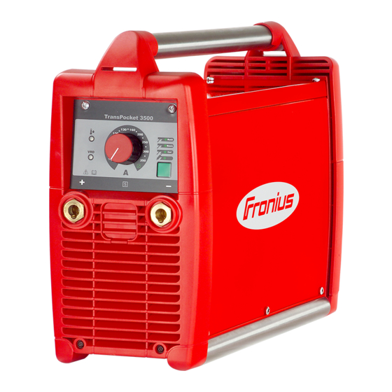
Page 17: Control Elements And Connections
Control elements and connections Safety WARNING! Danger due to incorrect operation and incorrectly performed work. This can result in serious injury and damage to property. ▶ All the work and functions described in this document must only be carried out by trained and qualified personnel. -
Page 18: Operating Elements
Rod electrode or grounding cable for manual metal arc (MMA) welding, depending on the type of electrode being used Grounding cable for TIG welding (-) current socket with bayonet latch For connecting the: Rod electrode or grounding cable for manual metal arc (MMA) welding, depending on the type of electrode being used Welding torch in TIG welding (current connection) Remote control connection socket... - Page 19 Lights up red when the Voltage Reduction Device (VRD) is active and the open circuit voltage is greater than 35 V Does not light up if an open circuit voltage outside the VRD range is set...
-
Page 20: Before Commissioning
Proper use The power source is intended exclusively for MMA welding and TIG welding in conjunc- tion with system components from Fronius. Utilisation for any other purpose, or in any other manner, shall be deemed to be not in accordance with the intended purpose. - Page 21 NOTE! An inadequately dimensioned electrical installation can cause serious damage. The mains lead and its fuse must be dimensioned to suit the local power supply. The technical data shown on the rating plate applies.
-
Page 22: Changing Mains Voltage (Only Mvm Versions)
Changing mains voltage (only MVm versions) General remarks MVm machines (MultiVoltage manual) are suitable for operation with a mains voltage of 380 - 460V and a mains voltage of 200 - 240V. NOTE! Machines are supplied with the 380 - 460V setting as standard. If the mains voltage range needs to be reset, this must be done manually. -
Page 23: Single-Phase Operation
380V - 460V 200V - 240V Single-phase MVm machines can be used in single phase operation (e.g. 1x230V) if required. operation However, this reduces the welding current range. Please see the "Technical Data" sec- tion for the relevant performance data. Fit the mains cable and mains plug in accordance with the applicable national standards. -
Page 24: Mma Welding
MMA welding Safety WARNING! Operating the equipment incorrectly can cause serious injury and damage. Do not use the functions described here until you have fully read and understood the fol- lowing documents: ▶ These Operating Instructions ▶ All the Operating Instructions for the system components, especially the safety rules WARNING! An electric shock can be fatal. -
Page 25: Hotstart Function (Used With Rutile And Cel Processes)
HotStart function Benefits: (used with rutile Improved ignition properties, even I (A) and Cel pro- when using electrodes with poor igni- 117A cesses) tion properties Better fusion of the base material dur- ing the start-up phase, meaning fewer cold-shut defects Largely prevents slag inclusions 1,5 s Example of HotStart function... -
Page 26: Tig Welding
TIG welding Safety WARNING! Operating the equipment incorrectly can cause serious injury and damage. Do not use the functions described here until you have fully read and understood the fol- lowing documents: ▶ These Operating Instructions ▶ All the Operating Instructions for the system components, especially the safety rules WARNING! An electric shock can be fatal. -
Page 27: Setting The Shielding Gas Flow Rate
Setting the CAUTION! shielding gas flow rate Risk of injury and damage from electric shock. As soon as the mains switch is in the "I" position, the tungsten electrode of the welding torch is LIVE. Make sure that the tungsten electrode does not touch any persons or elec- trically conductive or earthed parts (e.g. -
Page 28: Tig Comfort Stop Function
TIG Comfort Stop The "TIG Comfort Stop" function (TCS) is only available with the TP 2500/3500 TIG function power source. The TIG-Comfort-Stop function is deactivated as standard. Activating and setting the TIG Comfort Stop function is described in the "The Setup menu" section. If the TIG Comfort Stop function is deactivated, end crater filling through current decrease or gas shielding of the end crater does not occur. - Page 29 The gas post-flow time depends on the welding current selected and cannot be adjusted. Gas post-flow time with minimum welding current (10 A): 3 seconds Gas post-flow time with maximum welding current (250 A): 15 seconds The following diagram shows the welding current sequence and the gas flow when the TIG Comfort Stop function is activated: 250 A (max.)
-
Page 30: The Setup Menu
The Setup menu Setting options Welding process Settable parameters Factory setting Arc-force dynamic Level 2 Arc-force dynamic Level 2 Cel characteristic and arc-force dynamic Level 2 TIG Comfort Stop Level 0 Pulse frequency (TP 2500/3500 TIG only) Level 1 Functional prin- The parameters can be set at 4 levels (TP 2500/3500) or 5 levels (TP 2500/3500 TIG). -
Page 31: Arc-Force Dynamic Parameter
Arc-force The purpose of the arc-force dynamic dynamic para- parameter is to influence the short-circuit I (A) or U (V) meter amperage at the moment of droplet trans- fer. Level: 5 4 3 2 1 5 4 3 2 1 If the rod electrode has a tendency to stick, adjust the arc-force dynamic para- meter to a higher level. -
Page 32: Pulsing Frequency Parameter
Level Increase in arc size before function is triggered Small increase required Very small increase required TIG Comfort Stop deactivated (factory setting) Pulsing fre- The frequency parameter is only available on the TP 2500/3500 TIG power source and is quency para- used to set the frequency of the pulsed arc. -
Page 33: Voltage Reduction Device (Vrd Versions Only)
Voltage Reduction Device (VRD versions only) General A Voltage Reduction Device (VRD) is an optional safety device for reducing the voltage. As far as possible, VRD prevents output voltages at the current sockets that may pose a danger to persons. Safety principle Welding circuit resistance is greater than the minimum human body resistance... -
Page 34: Troubleshooting
Troubleshooting Safety WARNING! An electric shock can be fatal. Before opening the device ▶ Turn the mains switch to the "O" position ▶ Unplug the device from the mains ▶ Ensure the device cannot be switched back on ▶ Using a suitable measuring instrument, check to make sure that electrically charged components (e.g. - Page 35 No welding current Device switched on, indicator for the selected welding process is lit, error indicator lit Cause: Duty cycle exceeded - device overloaded - fan running Remedy: Keep within duty cycle Cause: Thermostatic automatic circuit breaker has switched off the device Remedy: Wait until the power source comes back on automatically at the end of the cooling phase (do not switch off the device - the fan will cool it down)
-
Page 36: Status Indicators
LED for set process is flashing Cause: Single-phase operation with a welding current greater than 140A Remedy: Select a welding current less than 140A and continue welding Cause: Phase failure Remedy: Check the mains lead Poor weld properties (severe spattering) Cause: Incorrect electrode polarity Remedy:... - Page 37 Ground current (earth current watchdog option only) Indicators shown on the right light up, VRD indicator flashes red Cause: Current flowing via device earth Remedy: Check ground earth connection to workpiece, switch machine off and on again; if error keeps recurring, have machine serviced Short circuit after switching on the machine Indicators shown on the right light up, VRD indicator flashes red...
-
Page 38: Care, Maintenance And Disposal
Care, maintenance and disposal General Under normal operating conditions, the power source requires only a minimum of care and maintenance. However, some important points must be noted to ensure that the welding system remains in a usable condition for many years. WARNING! An electric shock can be fatal. -
Page 39: Average Consumption Values During Welding
Average consumption values during welding Average wire Average wire electrode consumption at a wire speed of 5 m/min electrode con- 1.0 mm wire 1.2 mm wire 1.6 mm wire sumption during electrode dia- electrode dia- electrode dia- MIG/MAG welding meter meter meter Steel wire electrode... -
Page 40: Technical Data
Technical data Safety NOTE! An inadequately dimensioned electrical installation can cause serious damage. The mains lead and its fuse protection must be rated accordingly. The technical data shown on the rating plate applies. Generator- The power sources in the TP 2500/3500 series are totally generator-compatible, powered opera- provided that the maximum apparent power delivered by the generator is at least 14 kVA tion... -
Page 41: Transpocket 2500 Mvm, 2500 Tig Mvm
Max. shielding gas pressure (TIG) 12.5 bar kg 72.5 psi. Max. noise emission (LWA) 74 dB (A) Idle state power consumption at 400 V 23.4 W Power source efficiency at 250 A / 30 V TransPocket Mains voltage (U 200 V 230 V 2500 MVm, 2500 Max. -
Page 42: Transpocket 3500, 3500 Rc, 3500 Tig
Max. noise emission (LWA) 74 dB (A) Idle state power consumption at 400 V 23.4 W Power source efficiency at 250 A / 30 V TransPocket Mains voltage (U 380 V 400 V 460 V 3500, 3500 RC, Max. effective primary current (I 17.5 A 16.8 A 15.1 A... -
Page 43: Transpocket 3500 Mvm, 3500 Tig Mvm
TransPocket Mains voltage (U 200 V 230 V 3500 MVm, 3500 Max. effective primary current (I 27 A 24.7 A TIG MVm 1eff Max. primary current (I 45.6 A 41.8 A 1max Mains fuse protection 35 A slow-blow Mains voltage (U 380 V 400 V 460 V... -
Page 44: Overview With Critical Raw Materials, Year Of Production Of The Device
An overview of which critical raw materials are contained in this device can be found at materials, year of the following Internet address. production of the www.fronius.com/en/about-fronius/sustainability. device To calculate the year of production of the device: Each device is provided with a serial number... - Page 48 FRONIUS INTERNATIONAL GMBH Froniusstraße 1 A-4643 Pettenbach AUSTRIA contact@fronius.com www.fronius.com Under www.fronius.com/contact you will find the addresses of all Fronius Sales & Service Partners and locations...
Need help?
Do you have a question about the TransPocket 2500 and is the answer not in the manual?
Questions and answers